Advertisement
215-748 Rev. K; ECN 12-05-016F
© 2012 Bradley
Page 1 of 5
10/26/2012
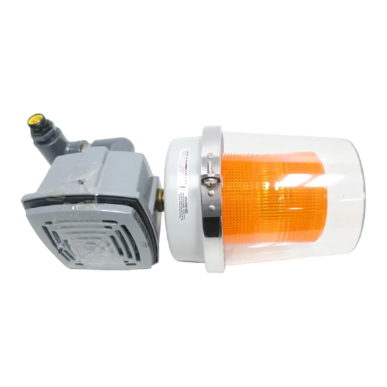
S19-320A (6' cable)
S19-320D (12' cable)
Flow Switch Alarm System
Table of Contents
Pre-Installation Information. . . . . . . . . . . . . . . . . . . . . . . . . 2
Assembly Of Components. . . . . . . . . . . . . . . . . . . . . . . . . . 3
Installation. . . . . . . . . . . . . . . . . . . . . . . . . . . . . . . . . . . . 4–5
Testing The Alarm System. . . . . . . . . . . . . . . . . . . . . . . . . . 6
Troubleshooting . . . . . . . . . . . . . . . . . . . . . . . . . . . . . . . . . 6
Strobe Flashtube Replacement . . . . . . . . . . . . . . . . . . . . . . 6
Alarm System Maintenance . . . . . . . . . . . . . . . . . . . . . . . . 6
Remote Sensing Option . . . . . . . . . . . . . . . . . . . . . . . . . . . 6
P.O. Box 309, Menomonee Falls, WI USA 53052-0309
PHONE 800.BRADLEY (800.272.3539) FAX 262.251.5817
bradleycorp.com
Advertisement
Table of Contents

Related Manuals for Bradley S19-320A


Summary of Contents for Bradley S19-320A
- Page 1 Remote Sensing Option ......6 215-748 Rev. K; ECN 12-05-016F P.O. Box 309, Menomonee Falls, WI USA 53052-0309 © 2012 Bradley PHONE 800.BRADLEY (800.272.3539) FAX 262.251.5817 Page 1 of 5 10/26/2012 bradleycorp.com...
- Page 2 Main water supply to the eyewash should be “ON” at all times. Provisions shall be made to prevent unauthorized shutoff. The ANSI Z358.1 standard requires an uninterrupted supply of flushing fluid. Bradley plumbed emergency fixtures require a minimum of 30 PSI (0.21 MPa) flowing pressure. Flushing fluid should be tepid per ANSI Z358.1.
- Page 3 Sensor Body Blue Green Brass Black Adapter and Tee 3.6" (91mm) ½" NPT Electrical Inlet and Connections Outlet IMPORTANT! Power Supply System is prewired. Installer connects ONLY ground black and white wires! Bradley • 215-748 Rev. K; ECN 12-05-016F 10/26/2012...
- Page 4 4. Replace the front grille onto the alarm horn casing being sure the prong plugs (that are part of the front grille) line up with the socket slots inside the casing. Tighten the two 5/64" hex screws. Test the alarm system. Bradley • 215-748 Rev. K; ECN 12-05-016F 10/26/2012...
- Page 5 7. Test the alarm as described in “Test the Alarm System.” Alarm system maintenance The Bradley Alarm System is designed to be virtually maintenance free. An occasional damp cloth wiping of the clear dust cover is all that is needed to ensure maximum visual attention-getting ability.
Need help?
Do you have a question about the S19-320A and is the answer not in the manual?
Questions and answers