Table of Contents
Advertisement
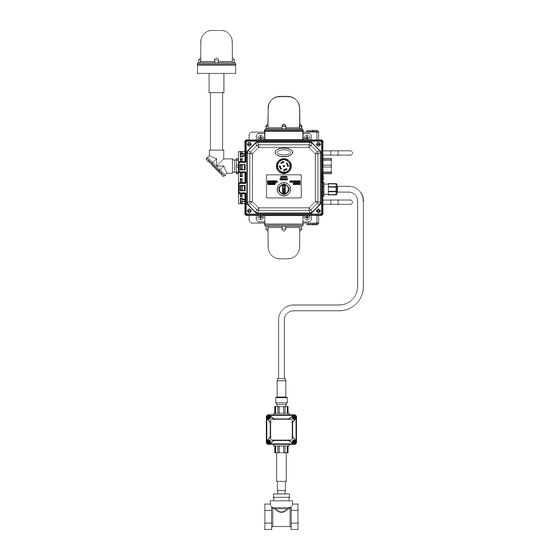
S19-324DGW shown
215-1846 Rev. C; ECN 17-05-068
© 2017 Bradley
Page 1 of 14
11/21/2017
Installation
S19-323
NEMA 3R
S19-324
NEMA 4X
Emergency Signaling System
Table of Contents
Pre-Installation Information . . . . . . . . . . . . . . . . . . . . . . . . . . 2-3
Components . . . . . . . . . . . . . . . . . . . . . . . . . . . . . . . . . . . . . . 4-5
Install Flow Switch and Mount Assembly . . . . . . . . . . . . . . . . 6
Connect Signaling Assembly to Flow Switch . . . . . . . . . . . . . . 7
Complete Electrical Supply Connections . . . . . . . . . . . . . . . . . 7
Test the Signaling System . . . . . . . . . . . . . . . . . . . . . . . . . . . . 8
Maintenance . . . . . . . . . . . . . . . . . . . . . . . . . . . . . . . . . . . . . . 8
Remote Sensing Option . . . . . . . . . . . . . . . . . . . . . . . . . . . . . . 8
Servicing of Lights . . . . . . . . . . . . . . . . . . . . . . . . . . . . . . . . . . 9
Troubleshooting . . . . . . . . . . . . . . . . . . . . . . . . . . . . . . . . . . . 10
Service Parts . . . . . . . . . . . . . . . . . . . . . . . . . . . . . . . . . . . 11-12
Wiring Diagram . . . . . . . . . . . . . . . . . . . . . . . . . . . . . . . . . . . 13
Schematic . . . . . . . . . . . . . . . . . . . . . . . . . . . . . . . . . . . . . . . 14
Menomonee Falls, WI 53052 USA
P.O. Box 309
800 BRADLEY (800 272 3539)
+1 262 251 6000
bradleycorp.com
Advertisement
Table of Contents

Related Manuals for Bradley S19-323


Summary of Contents for Bradley S19-323
-
Page 1: Table Of Contents
Schematic . . . . . . . . . . . . . . . . . . . . . . . . . . . . . . . . . . . . . . . 14 S19-324DGW shown P.O. Box 309 Menomonee Falls, WI 53052 USA 215-1846 Rev. C; ECN 17-05-068 800 BRADLEY (800 272 3539) © 2017 Bradley +1 262 251 6000 Page 1 of 14 11/21/2017... -
Page 2: Pre-Installation Information
Failure to do so may result in major product and/or property damage. Constant power supply to safety equipment is necessary for it to function. Avoid cleaners containing organic solvents, alcohols and hydrocarbons. Rinse with potable water after cleaning. Bradley • 215-1846 Rev. C; ECN 17-05-068 11/21/2017... - Page 3 The ANSI/ISEA Z358.1 standard requires an uninterrupted supply of flushing fluid. Bradley plumbed emergency fixtures require a minimum of 30 PSI (0.21MPa) flowing pressure.
-
Page 4: Components
Tee 1/2" (eyewash) 2-3/8" (60mm) for or 1-1/4" (drench eyewash or shower) NPT Inlet 3-9/16" (91mm) for and Outlet drench shower System is prewired. Installer connects ONLY ground black and white wires. Bradley • 215-1846 Rev. C; ECN 17-05-068 11/21/2017... - Page 5 ONLY ground black Body and white wires. Brass Adapter and Tee 2-3/8" (60mm) for 1/2" (eyewash) eyewash or or 1¼" (drench 3-9/16" (91mm) for shower) NPT Inlet drench shower and Outlet Bradley • 215-1846 Rev. C; ECN 17-05-068 11/21/2017...
-
Page 6: Install Flow Switch And Mount Assembly
U-bolts and nuts . • The signaling system can also be bolted to a flat surface such as a wall (hardware for this type of installation is NOT supplied) . Bradley • 215-1846 Rev. C; ECN 17-05-068 11/21/2017... -
Page 7: Connect Signaling Assembly To Flow Switch
. Compliance and conformity to Turn on supply power to the signaling local codes and ordinances is system .Test the signaling system at the responsibility of the installer. this time . Bradley • 215-1846 Rev. C; ECN 17-05-068 11/21/2017... -
Page 8: Test The Signaling System
. Signaling System Maintenance The Bradley Emergency Signaling System is designed to be virtually maintenance free . An occasional damp cloth wiping of the clear dust cover is all that is needed to ensure maximum visual attention-getting ability . -
Page 9: Servicing Of Lights
. which attach the light to the enclosure and remove light . This is a sealed light and has no serviceable components, the complete housing must be replaced . Bradley • 215-1846 Rev. C; ECN 17-05-068 11/21/2017... -
Page 10: Troubleshooting
Check that there is 24VDC being supplied from the power supply mounted on the print circuit board in the signal station enclosure . Component failure . Check light connections and filament in the light . Bradley • 215-1846 Rev. C; ECN 17-05-068 11/21/2017... -
Page 11: Service Parts
Qty. Description 160-467 Screw, 1/4-20x3/4 PN 300 SS 142-002AV Washer, .265x.500x.0.63 Flat 304SS 161-060 Nut, 1/4-20 SS Nylon Insert 269-594 U-Bolt, SS 161-065 Nut, 3/8-16 Hex 18-8SS 161-171 3/4 NPSM Conduit Locknut Bradley • 215-1846 Rev. C; ECN 17-05-068 11/21/2017... -
Page 12: Service Parts
Screw, 1/4-20x3/4 PN 300 SS 142-002AV Washer, .265x.500x.0.63 Flat 304SS 161-060 Nut, 1/4-20 SS Nylon Insert 269-594 U-Bolt, SS 161-065 Nut, 3/8-16 Hex 18-8SS 161-171 3/4 NPSM Conduit Locknut (for mounting to heat trace unit) Bradley • 215-1846 Rev. C; ECN 17-05-068 11/21/2017... -
Page 13: Wiring Diagram
S19-323, S19-324 Installation Wiring Diagram Bradley • 215-1846 Rev. C; ECN 17-05-068 11/21/2017... -
Page 14: Schematic
WIRE LIGHT INTERNAL JUMPER HORN TERMINAL BLOCK CONNECTION COMPONENT SOLDERED FLOW SWITCH CONNECTION NORMALLY OPEN FLOW SENSOR FUSE NORMALLY OPEN NORMALLY OPEN CONTACT SWITCH NORMALLY CLOSED NORMALLY CLOSED CONTACT SWITCH RELAY COIL Bradley • 215-1846 Rev. C; ECN 17-05-068 11/21/2017...
Need help?
Do you have a question about the S19-323 and is the answer not in the manual?
Questions and answers