Table of Contents
Advertisement
Quick Links
Advertisement
Table of Contents

Subscribe to Our Youtube Channel
Related Manuals for Wisenet TNF-9010


Summary of Contents for Wisenet TNF-9010
- Page 1 NETWORK CAMERA User Manual TNF-9010...
- Page 2 Network Camera User Manual Copyright ©2020 Co., Ltd. All rights reserved. Hanwha Techwin Trademark Each of trademarks herein is registered. The name of this product and other trademarks mentioned in this manual are the registered trademark of their respective company. Restriction Copyright of this document is reserved.
- Page 3 overview IMPORTANT SAFETY INSTRUCTIONS 23. This device has been verified using STP cable. The use of appropriate GND grounding and STP cable is recommended to effectively protect your product and property from transient voltage, thunderstroke, communication interruption. 1. Read these instructions. 2.
- Page 4 overview Class construction Please read the following recommended safety precautions carefully. An apparatus with CLASS construction shall be connected to a MAINS socket outlet with a ~ Do not place this apparatus on an uneven surface. protective earthing connection. ~ Do not install on a surface where it is exposed to direct sunlight, near heating equipment or heavy cold area.
-
Page 5: Table Of Contents
CONTENTS OVERVIEW Important Safety Instructions WEB VIEWER Connecting to the Camera Recommended PC Specifications Password setting Recommended Micro SD/SDHC/SDXC Login Memory Card Specifications Camera Web Viewer Setup NAS recommended specs What’s Included Optional Accessories for Installation At a Glance APPENDIX Troubleshooting INSTALLATION &... -
Page 6: Recommended Pc Specifications
overview RECOMMENDED PC SPECIFICATIONS NAS RECOMMENDED SPECS ~ CPU : Intel(R) Core(TM) i7 3.4 GHz or higher ~ Recommended capacity : 200GB or higher is recommended. ~ RAM : 8G or higher ~ For this camera, you are recommended to use a NAS with the following manufacturer’s specs. ~ Recommended browser: Chrome Recommended products : QNAP NAS, Synology NAS ~ Supported browsers: Chrome, Safari, Firefox, MS Edge(chromium based) -
Page 7: What's Included
WHAT’S INCLUDED Please check if your camera and accessories are all included in the product package. (As for each sales country, accessories are not the same.) Appearance Item Name Quantity Description Appearance Item Name Quantity Description Power Cable Used to plug into the power port Camera Machine Screws Used to attach the camera body to the mount plate... -
Page 8: Optional Accessories For Installation
You can purchase appropriate optional accessories available. Appearance Model name Hanging Mount Mount for race way SBP-300LMW (Parapet Mount) SBP-300CMW (Ceiling Mount) SBP-300WMW (Wall Mount) SBP-300WMW1 (Wall Mount) TNF-9010 SBP-167HMW SBP-122WM SBP-300NBW (Instalation Box) SBP-300NBW (Wall Mount Base) SBP-300PMW (Pole Mount) SBP-300KMW (Corner Mount) Item Description... - Page 9 Inside Rear side Item Description Connector cover An anti-dust rubber cover for DC 12V power and audio/alarm port. Plug in the audio and alarm cable to this port to connect with external alarm device/ Audio/Alarm cable port microphone/speaker. Power port (DC 12 V) Port for power terminal block.
-
Page 10: Installation & Connection
installation & connection INSTALLATION 2. Turn the top cover in the direction of the arrow to remove it. Precautions before installation Ensure you read out the following instructions before installing the camera: ~ Select an installation site that can hold at least 5 times the camera’s weight. ~ Stuck-in or peeled-off cables can cause damage to the product or a fire. - Page 11 Inserting a Micro SD card Removing a Micro SD card Slide the Micro SD card into the Micro SD card slot on the camera module in the direction of the arrow. Gently press down on the exposed end of the Micro SD card as shown in the diagram to eject the Micro SD card from the slot.
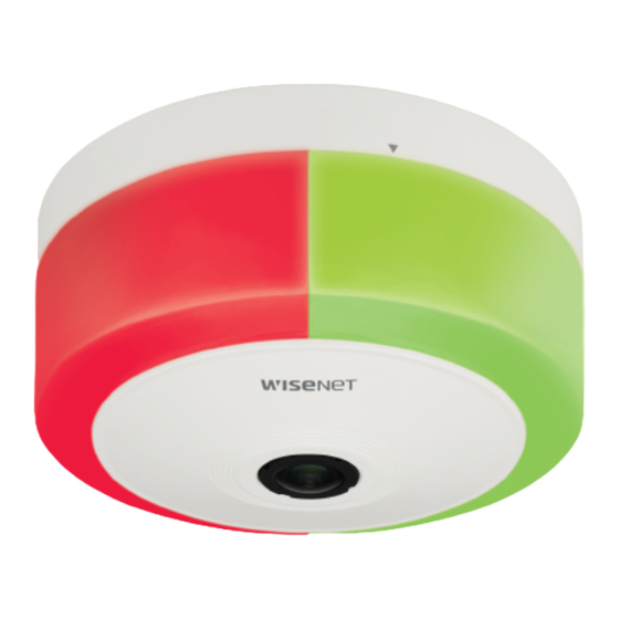
- Page 12 installation & connection LED integrated usage mode Attaching the camera to a mount or structure LED displays a single solid color regardless of the direction. 1. Install the mount plate using appropriate screws (not provided) in the location you want Single color LED separate usage mode The left and right sides (based on the logo position) of LED each display a different color.
- Page 13 [Installing the network cable] 5. Connect the power terminal block to the power port (DC 12 V) of the camera body. 3. Connect the network cable to the network port of the camera body. 6. After connecting the power cable, attach the connector cover again. [Installing the power cable (for DC power)] 4.
- Page 14 installation & connection [Installing audio/alarm cables] 9. After connecting the audio/alarm cable, attach the connector cover again. 7. Pass the audio/alarm cable through the connector cover as shown in the figure. 8. Connect the connector of the audio/alarm cable to the Audio/Alarm cable port. 10.
- Page 15 11. Adjust the lens to the desired direction with reference to “Adjusting the monitoring direction for the Adjusting the monitoring direction for the camera camera” section. (page 15) 12. Push the top cover on to the camera body with the installation direction guides aligned, and turn it in the direction of the arrow to join it.
-
Page 16: Connecting With Other Device
installation & connection CONNECTING WITH OTHER DEVICE Power Supply Use a screwdriver to connect the + and - lines of the power adaptor to the provided power terminal block, and then insert them in the power port (DC12V). You must connect the power terminal block connected with a DC12V power cable to the power port of the camera before plugging the power plug into the power socket. - Page 17 Connecting to Audio Input/Output Connecting to the I/O port box Connect the Alarm I/O cable to the corresponding port of the port box. Speaker Microphone Network Alarm Sensor (Warning lamp) ~ ALARM #1, ALARM #2 : These ports can be used as alarm input or output ports. If used as input ports, alarm input or day/night sensors can be connect to them.
- Page 18 installation & connection To connect the external sensor Connect one of the 2 signal lines to the [ALARM #1] port (if you want this to be the input port) and the remaining one to the [GND] port. Alarm In Wiring Diagram External Inside of the camera VCC_3.3V...
-
Page 19: Network Connection And Setup
network connection and setup CONNECTING THE CAMERA DIRECTLY TO A DHCP BASED DSL/CABLE You can set up the network settings according to your network configurations. MODEM CONNECTING THE CAMERA DIRECTLY TO LOCAL AREA NETWORKING Connecting to the camera from a local PC in the LAN INTERNET 1. -
Page 20: Using Device Manager
network connection and setup USING DEVICE MANAGER If using a Broadband Router ~ IP Address : Enter an address falling in the IP range provided by the Broadband Router. Device manager program can be downloaded from <Technical Support>-<Online Tool> menu at Hanwha Techwin website ex) 192.168.1.2~254, 192.168.0.2~254, (http://www.hanwha-security.com). -
Page 21: Manually Registering Camera
~ Example of the Dynamic IP environment configure the IP. TNF-9010 - If a Broadband Router, with cameras connected, is assigned an IP address by the DHCP server 2. Click < + > at the main page of device manager. -
Page 22: Port Range Forward (Port Mapping) Setup
Port forwarding can be done without additional router setup if the router supports the UPnP (Universal Plug and Play) function. For more information, refer to the user manual of the applicable router. After connecting the network camera, select the checkbox from the menu <Quick connect> in <Wisenet DDNS> in “Settings -> Network -> DDNS”. -
Page 23: Connecting To The Camera From A Shared Local Pc
2. From the remote PC, launch the Internet browser and type the DDNS URL address of the camera, or the IP address of the Broadband Router in the address bar. ex) http://ddns.hanwha-security.com/ID To use Wisenet DDNS, sign up at the Wisenet DDNS homepage (http://ddns.hanwha-security.com) and register the product at [My DDNS]>[Register Product]. English _23... -
Page 24: Connecting To The Camera
To register your device to the <DDNS> server, visit http://ddns.hanwha-security.com and register your device 1. Launch the Internet browser. first, and then set the Web Viewer’s <Network> - <DDNS> to <Wisenet DDNS>, as well as providing <Product ID> that had been used for DDNS registration. -
Page 25: Password Setting
PASSWORD SETTING CAMERA WEB VIEWER SETUP When you access the product for the first time, you must register the 1. Click the [Setup ( )] icon. login password. 2. The Settings window appears. 3. You can configure settings for the camera’s basic information, video, audio, network, event, analysis, and For a new password with 8 to 9 digits, you must use at least 3 of system over the network. -
Page 26: Troubleshooting
appendix appendix TROUBLESHOOTING PROBLEM SOLUTION PROBLEM SOLUTION When an Windows 10 user accesses ~ If the transmission method is set to multicast, check whether there is a router that supports ~ This is what happens when microphone driver has been set to Realtek driver. No image appears. - Page 27 Any changes or modifications in construction of this device which are not expressly approved by the party responsible for compliance could void the user's authority to operate the equipment. This device complies with part 15 of the FCC Rules. Operation is subject to the following two conditions: (1) This device may not cause harmful interference, and (2) this device must accept any interference received, including interference that may cause undesired operation.
Need help?
Do you have a question about the TNF-9010 and is the answer not in the manual?
Questions and answers