Table of Contents
Advertisement
Quick Links
Advertisement
Table of Contents

Related Manuals for Wisenet TNM-C3620TDR


Summary of Contents for Wisenet TNM-C3620TDR
- Page 1 THERMAL NETWORK CAMERA User Manual TNM-C3620TDR TNM-C3622TDR...
- Page 2 Thermal Network Camera User Manual Copyright ©2023 Co., Ltd. All rights reserved. Hanwha Vision Trademark Each of trademarks herein is registered. The name of this product and other trademarks mentioned in this manual are the registered trademark of their respective company. Restriction Copyright of this document is reserved.
- Page 3 overview IMPORTANT SAFETY INSTRUCTIONS 22. This device has been verified using STP cable. The use of appropriate GND grounding and STP cable is recommended to effectively protect your product and property from transient voltage, thunderstroke, communication interruption. 1. Read these instructions. 23.
- Page 4 overview Class construction Please read the following recommended safety precautions carefully. An apparatus with CLASS construction shall be connected to a MAINS socket outlet with a ~ Do not place this apparatus on an uneven surface. protective earthing connection. ~ Do not install on a surface where it is exposed to direct sunlight, near heating equipment or heavy cold area.
-
Page 5: Table Of Contents
CONTENTS OVERVIEW Important Safety Instructions WEB VIEWER Connecting to the Camera Recommended PC Specifications Password setting Recommended Micro SD/SDHC/SDXC Login Memory Card Specifications Camera Web Viewer Setup Recommended NAS Specifications What’s Included At a Glance APPENDIX Troubleshooting INSTALLATION & CONNECTION Inserting/Removing a Micro SD card Connecting with other Device NETWORK CONNECTION AND... -
Page 6: Recommended Pc Specifications
overview RECOMMENDED PC SPECIFICATIONS WHAT’S INCLUDED Please check if your camera and accessories are all included in the product package. ~ CPU : Intel(R) Core(TM) i7 3.4 GHz or higher (As for each sales country, accessories are not the same.) ~ RAM : 8G or higher ~ Recommended browser: Chrome Appearance... -
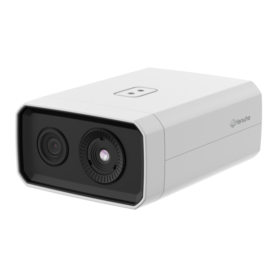
Page 7: At A Glance
AT A GLANCE Rear Side Front Side c d e f Item Description Item Description Used to discharge a lighting or a surge current outside in order to protect a camera from it Visible lens Used to see the visible view. GND Terminal safely. -
Page 8: Installation & Connection
installation & connection installation & connection INSERTING/REMOVING A MICRO SD CARD Removing a Micro SD card Gently press down on the exposed end of the Micro SD card as shown in the figure below to eject the Micro SD card from the slot. Remove Micro SD card cover Using the Torx L wrench, unscrew a screw that fastens the dust-resistant cover of the Micro SD card slot, and then remove the cover so you can insert the Micro SD card. -
Page 9: Connecting With Other Device
Camera Setup 1. Connect OTG adapter (5-pin) and WiFi dongle to the micro USB port. Smartphone Setup 1. Install the Wisenet Installation application. Grounding cable 2. Select the camera SSID after turning on the WiFi. 3. Run the Wisenet Installation application. - Page 10 installation & connection Powering and networking Power Supply Connect the PoE+ device with the PoE+ port of the camera. Use the screwdriver to connect each line (+, –) of the power cable to the corresponding power port of the camera. If the power sources for PoE+ and DC 12 V are simultaneously turned on, the device power will be supplied by both of PoE+ Connect and use a PoE+ enabled router.
- Page 11 Grounding the Product Connecting to Audio Input/Output Connect the ground wire to the ground terminal which is located above the power input terminal by using a screwdriver. Grounding protects the product from a surge or lightning. Speaker When grounding, make sure to turn the product’s power off. Recommended Grounding Cable Microphone ~ Length : Less than 3M...
- Page 12 installation & connection Connecting to the I/O port box To connect the external sensor Connect the Alarm I/O cable to the corresponding port of the port box. Connect one signal line of a 2-wire sensor to the [ALARM IN] port and connect the other wire to the [GND] port.
-
Page 13: Network Connection And Setup
network connection and setup CONNECTING THE CAMERA DIRECTLY TO A DHCP BASED DSL/CABLE You can set up the network settings according to your network configurations. MODEM CONNECTING THE CAMERA DIRECTLY TO LOCAL AREA NETWORK Connecting to the camera from a local PC in the LAN INTERNET 1. -
Page 14: Using Device Manager
network connection and setup USING DEVICE MANAGER If using a Broadband Router ~ IP Address : Enter an address falling in the IP range provided by the Broadband Router. Device manager program can be downloaded from <Support>-<Online Tool> menu at Hanwha Vision website ex) 192.168.1.2~254, 192.168.0.2~254, (https://www.HanwhaVision.com). -
Page 15: Registering Camera Manually
~ Example of the Dynamic IP environment configure the IP. TNM-C3620TDR - If a Broadband Router, with cameras connected, is assigned an IP address by the DHCP server 2. Click < + > at the main page of the device manager. -
Page 16: Port Range Forward (Port Mapping) Setup
network connection and setup PORT RANGE FORWARD (PORT MAPPING) SETUP Setting up Port Range Forward for several network cameras ~ You can set a rule of Port Forwarding on the Broadband Router device through its configuration web page. If you use a Broadband Router with a camera connected, you must set the port range forwarding on the ~ A user can change each port using the camera setting screen. -
Page 17: Connecting To The Camera From A Shared Local Pc
CONNECTING TO THE CAMERA FROM A SHARED LOCAL PC 1. Run the device manager. It searches connected cameras and displays them as a list. 2. Double-click a camera to access. The Internet browser opens and the camera is connected. Access to the camera can also be available by typing the camera’s IP address in the address bar of the Internet browser. CONNECTING TO THE CAMERA FROM A REMOTE PC VIA THE INTERNET On a remote computer that is in the Broadband Router’s network cluster, users can access cameras within a... -
Page 18: Connecting To The Camera
web viewer web viewer CONNECTING TO THE CAMERA Connecting via Bonjour 1. Run the client or operating system to support the Bonjour protocol. Normally, you would 2. Click the camera name for search. In the Mac operating system, click the camera name searched from the Bonjour tab of Safari. 1. -
Page 19: Password Setting
PASSWORD SETTING CAMERA WEB VIEWER SETUP When you access a camera for the first time, you must register its 1. Click the [Setup ( )] icon. login password. 2. The Settings window appears. 3. You can configure settings for the camera’s basic information, video, audio, network, event, analysis, and system over the network. -
Page 20: Troubleshooting
appendix TROUBLESHOOTING PROBLEM SOLUTION PROBLEM SOLUTION When an Windows 10 user accesses ~ Verify the settings in the following sequence: <Motion detection> of <Analytics> is ~ This is what happens when microphone driver has been set to Realtek driver. the web viewer through Chrome set to <Enable>, but no notification A. - Page 21 Any changes or modifications in construction of this device which are not expressly approved by the party responsible for compliance could void the user's authority to operate the equipment. This device complies with part 15 of the FCC Rules. Operation is subject to the following two conditions: (1) This device may not cause harmful interference, and (2) this device must accept any interference received, including interference that may cause undesired operation.
Need help?
Do you have a question about the TNM-C3620TDR and is the answer not in the manual?
Questions and answers