
Subscribe to Our Youtube Channel
Related Manuals for Wisenet TNO-X6072EPT1-Z


Summary of Contents for Wisenet TNO-X6072EPT1-Z
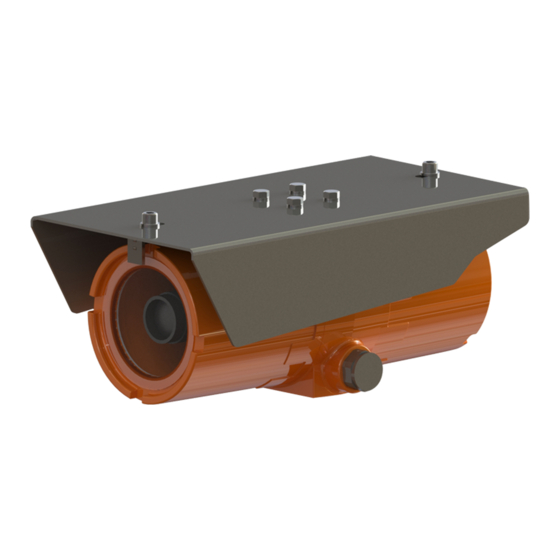
- Page 1 Explosion Proof Network Camera Installation Manual TNO-X6072EPT1-Z TNO-X8072EPT1-Z TNO-X6322EPT1-Z...
- Page 2 Produced in partnership by Spectrum Camera Solutions LLC & Hanwha Techwin America. Information in this document is subject to change without notice. All terms mentioned in this manual that are known to be trademarks have been appropriately capitalized. Spectrum Camera Solutions LLC acknowledges all trademark(s) and the rights of the trademark(s) owned by the company referred to herein.
-
Page 3: Table Of Contents
Table of Contents Legal Notices and Revision History Inside front cover Page LEGAL NOTICES & DESCRIPTION LABELS STANDARDS AND CERTIFICATIONS DOCUMENT SYMBOLS HOW TO USE THIS MANUAL GENERAL SAFETY AND OPERATING INFORMATION SPECIFICATIONS UNBOXING/HARDWARE WIRING ENTRIES INSTALLATION DISMANTLING AND MAINTENANCE... -
Page 4: Legal Notices & Description
Copyright Notice: This document contains information proprietary to Spectrum Camera Solutions LLC with all rights reserved worldwide. Any reproduction or disclosure of this publication, or any part thereof, to persons other than Spectrum Camera Solutions LLC personnel or customers is strictly prohibited, except by written permission of Spectrum Camera Solutions LLC. -
Page 5: Labels
Labels... -
Page 6: Standards And Certifications
STANDARDS & CERTIFICATIONS STANDARDS- The equipment is manufactured in accordance with the IECEX scheme, the ATEX Directive 2014/34/EU and with the following standards : IEC 60079-0:2011 IEC 60079-1:2014 IEC 60079-31:2013 IEC 60529:2013 EN 60079-0:2012 + A11:2013 EN 60079-1:2014 EN 60079-31:2014 EN 60529:1991 + A1:2000 + A2:2013 ANSI/ISA 60079-0:2013 ANSI/UL 60079-1:2015... -
Page 7: Document Symbols
DOCUMENT SYMBOLS The following symbols are used throughout this manual to alert users to potential hazards or important information. Failure to heed the warnings and cautions listed herein can lead to injury and equipment damage. Symbol Label Description Consists of conditions, practices, or procedures that WARNING: must be observed to prevent personal injury and/or equipment damage. -
Page 8: How To Use This Manual
How to use this Manual General Manual: This manual is intended to be used in conjunction with installed equipment manual from internal equipment manufacturer. Note: In the event of a conflict between the requirements of this general installation manual and the internal equipment manual, the safety and installation procedures described in this manual shall take precedence. -
Page 9: General Safety And Operating Information
General Safety and Operating Information: General safety and operating information applicable to electrical equipment installed within hazardous locations. This information must be understood by all persons installing, using, or maintaining the electrical equipment. This information is designed to aid personnel in safe installation, operation, and maintenance of the “TNO-XnnnnEPT1-Z"... - Page 10 General Safety and Operating Information: Electrical Power: The “TNO-XnnnnEPT1-Z" Series IP cameras operate from a variety of power options including IEEE 802.3af compliant POE devices. The power supply used with this product shall fulfill the requirements for Safety Extra Low Voltage (SELV) and Limited Power Source (LPS) according to IEC/EN/UL 62368-1 or IEC/EN/UL 60950-1 or Listed Class II Power Source Equipment.
- Page 11 General Safety and Operating Information: Installation: The installation must be realized in accordance with IEC/EN 60079-14 and/or in accordance with the national requirements. This equipment must be installed and used only by qualified personnel, having knowledge concerning electrical equipment for use in potentially explosive areas containing gas and/or dust.
-
Page 12: Specifications
II 2 G Ex db IIB+H2 T5 Gb Ta = -50°C to +55°C, IP66 II 2 D Ex tb IIIC T85°C Db Ta = -50°C to +55°C, IP66 CERT NO. FM18ATEX0073X & IECEx FMG 18.0029X ELECTRICAL REQUIREMENTS of Model TNO-X6072EPT1-Z POWER Camera: IEEE 802.3af Type 3 7.5W Heating: ;... - Page 13 Power Source Specification For TNO-X6072EPT1-Z, TNO-X8072EPT1-Z, TNO-X6322EPT1-Z The power supply used with this product shall have a rated output voltage within voltage range of 8-28 V DC.
-
Page 14: Unboxing/Hardware
UNBOXING... - Page 15 HARDWARE 1- (QTY 1) TNO-XnnnnEPT1-Z - CAMERA ASSEMBLY 2- (QTY 1) SUN SHIELD 3- (1 SET) .250-20 HEX SCREW 4- (1 SET) SPLIT LOCK WASHER 5- HT-F1XX-WM (WALL MOUNT NOT INCLUDED) 6- (QTY 2) SUN SHIELD STOP 7. ( 1 SET) .3125-18 PAN HEAD SCREW 8.
-
Page 16: Wiring Entries
WIRING ENTRIES ¾” NPT PORT ¾” NPT PORT Conduit Entries are ¾ inch NPT Use appropriate adapter to keep ingress protection CAUTION: Ensure power is disconnected prior to connecting... -
Page 17: Installation
INSTALLATION 2. Loosen set screw and remove ¼-20 hex screws then lift the sunshield from the camera housing. Tabletop Figure 2.1 ¼-20 hex screws Figure 2.1 screw Figure 2.2 -If wall mounted, remove sunshield stop. 3. Unscrew end cap from housing, revealing terminal blocks and the rear of the camera. - Page 18 INSTALLATION 4. Push release on terminal block and insert positive 12-28vdc connection into terminal block (+A) , release to secure. Do the same for negative dc connection into terminal block (-B). Figure 4.
- Page 19 INSTALLATION 5. The product shall be grounded either through a shielded network cable (STP) or other appropriate method. 5.1 Crimp RJ-45 using T568B color code then plug Cat6 POE into the RJ-45 Port located on the back of the Camera. 5.2 Internal grounding screw 5850-6 SLBHUC 10-24x ¼...
- Page 20 INSTALLATION 7. Ensure threads and gaskets are free of dirt and debris. 8. Reinstall TNO-XnnnnEPT1-Z end cap by hand to tighten by turning clockwise until hand tight and gasket is seated Figure 8. 9. Tighten both set screws on the end cap and lens cap ends of the housing. Figure 9.
-
Page 21: Dismantling And Maintenance
DISMANTLING & MAINTENANCE Dismantling: All repairs of explosion-proof equipment must be made according the specified criteria of IEC/EN 60079-19 rule by qualified personnel, having knowledge concerning electrical equipment for potentially explosive areas containing gas and/or dust. Qualified personnel must have knowledge regarding the types of explosion protection. Maintenance: The maintenance must be realized in accordance with IEC/EN 60079-17 and/or in accordance with the national requirements. - Page 22 HT-F1XX-WM Wall Mount...
- Page 23 HT-SPMA-SD Pole Mount Adapter HARDWARE QTY 4 7/8-20 18-8 Bolts QTY 2 12in all thread with nuts and washers QTY 2 A1612 sides...
- Page 24 HT-SD-CM Corner Mount HARDWARE- QTY 4 7/8-20 18-8 Bolts...
- Page 25 SD-VM Vibration Mount HARDWARE- QTY 4 7/8-20 18-8 Bolts FRONT...
- Page 26 SD-SO Standoff Mount HARDWARE- QTY 4 7/8-20 18-8 Bolts FRONT BACK...
- Page 27 Accessory Mounting Diagram HT-F1XX-WM+SD-VM+SD-SO+HT-SD-PMA HT-F1XX-WM+HT-SD-PMA...
- Page 28 Hanwha Techwin America 500 Frank W. Burr Blvd. Suite 43 Teaneck, NJ 07666 Toll Free +1.877.213.1222 Direct +1.201.325.6920 Fax +1.201.373.0124 www.hanwhasecurity.com...
Need help?
Do you have a question about the TNO-X6072EPT1-Z and is the answer not in the manual?
Questions and answers