Table of Contents
Advertisement
Quick Links
Advertisement
Table of Contents

Subscribe to Our Youtube Channel
Related Manuals for Lectrosonics IFBT4/X


Summary of Contents for Lectrosonics IFBT4/X
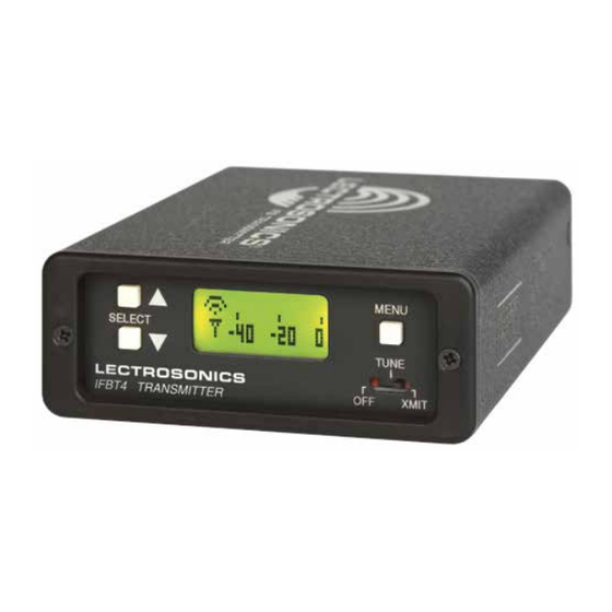
- Page 1 INSTRUCTION MANUAL IFBT4 Synthesized UHF IFB Transmitter IFBT4, IFBT4/E01, IFBT4/X Featuring Digital Hybrid Wireless Technology ™ U.S. Patent 7,225,135 Fill in for your records: Serial Number: Purchase Date: Rio Rancho, NM, USA www.lectrosonics.com...
- Page 2 IFBT4, IFBT4/E01, IFBT4/X LECTROSONICS, INC.
-
Page 3: Table Of Contents
Multi-Frequency IFB Transmitter Table of Contents General Technical Description ................................4 Introduction ......................................4 Audio Input Interface .....................................4 Input Limiter ......................................4 Audio DSP and Noise Reduction ................................5 Pilot Tone Squelch System ...................................5 Frequency Agility....................................5 Power Delay ......................................5 Microcontroller ......................................5 Transmitter ......................................5 Antenna System ....................................5 Front Panel Controls and Functions ..............................6 IFBT4 Front Panel ....................................6 OFF/TUNE/XMIT Switch ..................................6... -
Page 4: General Technical Description
The IFBT4 IFB transmitter brings DSP capability and a The standard 3 pin XLR connector on the rear panel convenient LCD interface to the popular Lectrosonics handles all audio inputs. The four DIP switches allow IFB product line. Replacing the venerable IFBT1 trans-... -
Page 5: Audio Dsp And Noise Reduction
Pilot Tone Squelch System Antenna System Lectrosonics IFB systems use a special “pilot tone” so that valid IFB signals can be distinguished from RF The 50 Ohm BNC output connector will work with stan- interference. During normal operation, an IFB receiver dard coaxial cabling and remote antennas. -
Page 6: Front Panel Controls And Functions
MHz, as well as the standard grade the quality of the audio. The 35 Hz setting may Lectrosonics hex code for use with transmitters equipped be used in the absence of adverse conditions, for a with hex switches. Also displayed is the UHF television fuller bass response. -
Page 7: Compat Setup Screen
Multi-Frequency IFB Transmitter COMPAT Setup Screen IFB - Lectrosonics IFB compatibility mode. This is the The COMPAT setup screen selects default setting and is the appropriate setting to the current compatibility mode, for use with the Lectrosonics IFBR1A or a compat- interoperation with various types of receivers. -
Page 8: Tuning Setup Screen
IFBT4, IFBT4/E01, IFBT4/X TUNING Setup Screen User Programmable Frequency Group Behavior The user programmable frequency groups “U” or “V” The TUNING setup screen allows work very similarly to the factory groups with a few selection of one of four factory set exceptions. -
Page 9: Rear Panel Controls And Functions
Multi-Frequency IFB Transmitter Rear Panel Controls and Functions IFBT4 Rear Panel Power Input Connector The IFBT4 is designed to be used with the DCR12/A5U external (or equivalent) power source. The nominal voltage to operate the unit is 12 VDC, although it will operate at voltages as low as 6 VDC and as high as 18 VDC. -
Page 10: Installation And Operation
IFBT4, IFBT4/E01, IFBT4/X Installation and Operation 1) The IFBT4 transmitter is shipped with pin 1 of the 4) Insert the microphone or other audio source XLR XLR input connector tied directly to ground. If a plug into the input jack. Ensure that the pins are floating input is desired, a Ground Lift Jumper is aligned and that the connector locks into place. -
Page 11: Supplied Accessories
35679 Lectrosonics screwdriver and adjustment tool for setting transmitter gain and roll-off pots as well as for setting the frequency switches on some older receivers and transmitters. -
Page 12: Optional Accessories
IFBT4, IFBT4/E01, IFBT4/X Optional Accessories SNA600 Collapsible dipole antenna that adjusts over a wide frequency range. Ideal for situations where a full SNA600 360 degree receiving pattern is required as op- posed to a directional pattern. ALP Series Antennas ALP500, ALP620 & ALP650 Shark Fin style Log... -
Page 13: Uhf Transmitter Antenna Specifications
Note: Check the scale of your printout. This line should be 6.00 inches long (152.4 mm). Measure from this edge of the housing BLOCK FREQUENCY ANTENNA RANGE COLOR WHIP LENGTH Lectrosonics A500RA UHF 470.100 - 495.600 Black 4.73” transmitter antennas follow the color code specifications 486.400 - 511.900 Black 4.51”... -
Page 14: Specifications
IFBT4, IFBT4/E01, IFBT4/X Specifications Signal to Noise Ratio: 90 dB typical (“A” weighted) Output Impedance: 50 ohms Audio Input Levels: • 0 dBu for Line, RTS1 & RTS2 Operating Frequencies (MHz): • -10 dBu for Clear Com E01 and X •... -
Page 15: Troubleshooting
Multi-Frequency IFB Transmitter Troubleshooting NOTE: Always ensure that the COMPAT (compatibility) setting is the same on both transmitter and receiver. A variety of different symptoms will occur if the settings do not match. With the IFBR1a receiver no sound will be heard unless the transmitter is set to the IFB mode. When used with receivers other than the IFBR1a, a variety of symptoms will occur when the COMPAT settings do not match, ranging from no sound, to level inconsistencies, to distortion of various degrees. -
Page 16: Service And Repair
There are no adjustments inside that will make a malfunctioning unit start working. LECTROSONICS’ Service Department is equipped and staffed to quickly repair your equipment. In warranty repairs are made at no charge in accordance with the terms of the warranty. Out-of-warranty repairs are charged at a modest flat rate plus parts and shipping. - Page 18 IFBT4, IFBT4/E01, IFBT4/X LECTROSONICS, INC.
- Page 19 Multi-Frequency IFB Transmitter Rio Rancho, NM...
- Page 20 This warranty does not apply to used or demonstrator equipment. Should any defect develop, Lectrosonics, Inc. will, at our option, repair or replace any defective parts without charge for either parts or labor. If Lectrosonics, Inc. cannot correct the defect in your equipment, it will be replaced at no charge with a similar new item.
Need help?
Do you have a question about the IFBT4/X and is the answer not in the manual?
Questions and answers