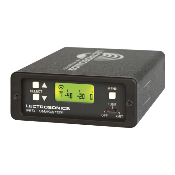
Lectrosonics IFBT4 Instruction Manual
Synthesized uhf ifb transmitter
Hide thumbs
Also See for IFBT4:
- Quick start manual (9 pages) ,
- Quick start manual (9 pages) ,
- Instruction manual (20 pages)
Table of Contents
Advertisement
Quick Links
Advertisement
Table of Contents

Summary of Contents for Lectrosonics IFBT4
- Page 1 INSTRUCTION MANUAL IFBT4 Synthesized UHF IFB Transmitter Includes Firmware Ver. 1.4 Featuring Digital Hybrid Wireless Technology ™ U.S. Patent 7,225,135 Fill in for your records: Serial Number: Purchase Date: Rio Rancho, NM, USA www.lectrosonics.com...
- Page 2 IFBT4 LECTROSONICS, INC.
-
Page 3: Table Of Contents
Table of Contents General Technical Description ................................4 Introduction ......................................4 Digital Hybrid Technology..................................4 Audio Input Interface .....................................4 IFBT4 Transmitter Block Diagram ..............................4 Input Limiter ......................................5 Audio DSP and Noise Reduction ................................5 Pilot Tone Squelch System ...................................5 Frequency Agility....................................5 Power Delay ......................................5 Microcontroller ......................................5... -
Page 4: General Technical Description
IFB product line. Replacing the venerable IFBT1 trans- Series and Venue receivers. The Lectrosonics Digital mitter, the IFBT4 retains the same physical size and is Hybrid system in the 400 Series mode overcomes fully interchangeable with its predecessor in terms of channel noise and compandor artifacts in a dramatically audio, RF and power interfaces. -
Page 5: Input Limiter
IFB audio quality. The IFBT4 performs these traditionally analog functions The IFBT4 transmitter operates at a high RF power entirely in the digital domain, maintaining historical level to ensure a clean signal free of dropouts and compatibility while requiring fewer adjustments. -
Page 6: Front Panel Controls And Functions
The ROLLOFF setup screen controls Frequency Window the low frequency audio response of the IFBT4 by moving the 3 dB corner of a 4 pole low- Pressing the MENU button once from pass digital filter. The 50 Hz setting is the default, and... -
Page 7: Compat Setup Screen
(Groups U and V) or the choice to not use groups at all. IFB - Lectrosonics IFB compatibility mode. This is the default setting and is the appropriate setting to In the four factory set frequency groups, eight frequen- use with the Lectrosonics IFBR1A or a compat- cies per group are preselected. -
Page 8: Frequency Window Behavior, Based On Tuning Mode Selections
IFBT4 Frequency Window Behavior, based on Adding/Deleting User Programmable TUNING mode selections Frequency Group Entries If NORMAL tuning mode is selected, the Up and Down Note: Each User Programmable Frequency Group buttons select the operating frequency in single chan- (“u” or “v”) has separate contents. We recommend... -
Page 9: Rear Panel Controls And Functions
Installation and Operation section. Power Input Connector MODE Switches The IFBT4 is designed to be used with the CH20 exter- nal (or equivalent) power source. The nominal voltage The MODE switches allow the IFBT4 to accommodate to operate the unit is 12 VDC, although it will operate a variety of input source levels by changing the input at voltages as low as 6 VDC and as high as 18 VDC. -
Page 10: Installation And Operation
IFBT4 Installation and Operation 1) The IFBT4 transmitter is shipped with pin 1 of the 4) Insert the microphone or other audio source XLR XLR input connector tied directly to ground. If a plug into the input jack. Ensure that the pins are floating input is desired, a Ground Lift Jumper is aligned and that the connector locks into place. -
Page 11: Accessories
RG-8 with the 21472 same 0.400” diameter. Available in 25, 50 and 100 foot lengths. RMP195 4 channel rack mount for up to four IFBT4 transmitters. Rocker switch included to work as a master power switch if desired. 21425 Locking collar with 21586 5/16”-32 thread... -
Page 12: Troubleshooting
IFBT4 Troubleshooting NOTE: Always ensure that the COMPAT (compatibility) setting is the same on both transmitter and receiver. A variety of different symptoms will occur if the settings do not match. With the IFBR1a receiver no sound will be heard unless the transmitter is set to the IFB mode. When used with receivers other than the IFBR1a, a variety of symptoms will occur when the COMPAT settings do not match, ranging from no sound, to level inconsistencies, to distortion of various degrees. -
Page 13: Frequency Blocks And Ranges
IFBT4 Transmitter. it is a special case in an 8 mHz band with 78 frequency Each IFBT4 transmitter is built to cover a pre-selected channels. range of frequencies (a “block”) as shown below. The... -
Page 14: Specifications
Operation of this device is subject to the following two conditions: (1) this device may not cause interference, and The IFBT4 transmitter is FCC type accepted under Part 74: 470 - 608MHz, 614 - 806MHz and 944.1 – 951.9MHz. (2) this device must accept interference, including interference This device complies with FCC radiation exposure limits as set forth for an uncontrolled that may cause undesired operation of the device. -
Page 15: Service And Repair
There are no adjustments inside that will make a malfunctioning unit start working. LECTROSONICS’ Service Department is equipped and staffed to quickly repair your equipment. In warranty repairs are made at no charge in accordance with the terms of the warranty. Out-of-warranty repairs are charged at a modest flat rate plus parts and shipping. -
Page 16: Limited One Year Warranty
This warranty does not apply to used or demonstrator equipment. Should any defect develop, Lectrosonics, Inc. will, at our option, repair or replace any defective parts without charge for either parts or labor. If Lectrosonics, Inc. cannot correct the defect in your equipment, it will be replaced at no charge with a similar new item.


Need help?
Do you have a question about the IFBT4 and is the answer not in the manual?
Questions and answers