
Related Manuals for Generac Mobile MLT6SMDS


Summary of Contents for Generac Mobile MLT6SMDS
- Page 1 Owner’s Manual Light Tower MLT6SMDS • MLT6SKDS SN ________________ and Higher 008615 For technical assistance contact: www.generacmobileproducts.com Technical Support 1-800-926-9768 SAVE THIS MANUAL FOR FUTURE REFERENCE...
- Page 2 Engine and generator serial numbers are located on data Unit Serial No. plates affixed to the engine and generator, respectively. When contacting a Generac Mobile Authorized Service Engine Model No. Dealer (GMASD) about parts and service, always provide the unit model and serial number.
-
Page 3: Table Of Contents
Table of Contents Section 1: Introduction and Safety Raising the Mast—Electric Winch (If Equipped) ............23 Introduction ............1 Raising the Mast—Power Zone-DLA (If Read This Manual Thoroughly ........1 Equipped) ............24 How to Obtain Service ..........1 Prestart Checklist ..........25 Safety Rules ............1 Starting the Unit (Key Switch Models) .... - Page 4 Section 6: Wiring Diagrams Mast Junction Box Wiring and Light Connections ............43 AC Wiring—MLT6SKDS ........44 AC Wiring—MLT6SMDS ........45 AC Wiring—MLT6SMDS With Power Zone (If Equipped) ............46 AC Wiring—MLT6SKDS With Power Zone (If Equipped) ............47 DC Wiring—MLT6SMDS ........48 DC Wiring—MLT6SMDS With Power Zone (If Equipped) ............49...
-
Page 5: Section 1: Introduction And Safety
Section 1: Introduction and Safety Introduction Safety Rules Thank you for purchasing a Generac Mobile product. This The manufacturer cannot anticipate every possible unit has been designed to provide high performance, circumstance that might involve a hazard. The warnings in... -
Page 6: General Hazards
Introduction and Safety General Hazards Explosion and Fire Hazards DANGER DANGER Asphyxiation. Running engines produce carbon Explosion and Fire. Fuel and vapors are extremely flammable and explosive. Add fuel in a well monoxide, a colorless, odorless, poisonous ventilated area. Keep fire and spark away. Failure gas. -
Page 7: Electrical Hazards
Introduction and Safety Electrical Hazards Battery Hazards DANGER DANGER Electrocution. In the event of electrical accident, Electrocution. Do not wear jewelry while immediately shut power OFF. Use non-conductive working on this equipment. Doing so will implements to free victim from live conductor. Apply result in death or serious injury. -
Page 8: Fuel Hazards
Introduction and Safety Fuel Hazards Operating Safety DANGER Positioning the Unit Explosion and fire. Fuel and vapors are extremely DANGER flammable and explosive. No leakage of fuel is High Voltage. Verify area above unit is clear permitted. Keep fire and spark away. Failure to do of overhead wires and obstructions. -
Page 9: Raising And Lowering The Mast
Introduction and Safety Raising and Lowering the Mast Service Safety WARNING This unit uses high voltage circuits capable of causing serious injury or death. Only a qualified and licensed Electrocution. Do not set up or operate electrician should troubleshoot or repair problems this unit if severe weather is expected. -
Page 10: Towing Safety
Gross Vehicle Weight Rating (GVWR). Generac Mobile. Verify the trailer hitch and the coupling are • To contact NHTSA, you may either call the Auto Safety compatible. -
Page 11: Section 2: General Information
Section 2: General Information Specifications Description Unit of Measure MLT6SMDS MLT6SKDS Engine Make (Model) — ® ® Mitsubishi (L3E) Kubota (D1005) EPA Certification Tier 4 Final 4 Final Type — Diesel, liquid cooled Diesel, liquid cooled Horsepower—Prime hp (kW) 11.3 (8.4) 11.7 (8.7) -
Page 12: Unit Dimensions
General Information Unit Dimensions 008644 Figure 2-1. Unit Dimensions 118 in (3 m) 101 in (2.6 m) 23 ft (7 m) 57 in (1.5 m) 120.5 in (3.1 m) Owner’s Manual for Mobile Light Tower... -
Page 13: Unit Serial Number Locations
(920) 361-4442 (800) 926-9768 Country of Origin Model Serial Number TIRE AND LOADING INFORMATION DATE: 00/0000 MANUFACTURED BY/FABRIQUE PAR: Generac Mobile Products LLC RENSEIGNEMENTS SUR LES COLD INF. PRESS./ GVWR/PNBV: 000KG (0000LBS) Manufacturing Code Weight (lbs/kg) RPM/Frequency PNEUS ET LE CHARGEMENT PRESS. -
Page 14: Trailer Tongue Storage And Tow Positions
General Information Trailer Tongue Storage and Tow CAUTION Positions Pinching and crushing hazard. To avoid The trailer tongue is designed to fold upright for shipping possible injury, keep fingers away from pivot and storage. point when folding or unfolding trailer tongue. IMPORTANT NOTE: Do not attempt to tow the unit (000313) with trailer tongue in the storage position. -
Page 15: Place Trailer Tongue In Storage Position
General Information Place Trailer Tongue in Storage Position 1. Verify unit is on a level surface and wheels are blocked. 2. See Figure 2-7. Extend jack (A) enough to allow minimum effort to pivot trailer tongue into storage position. 003591 Figure 2-9. -
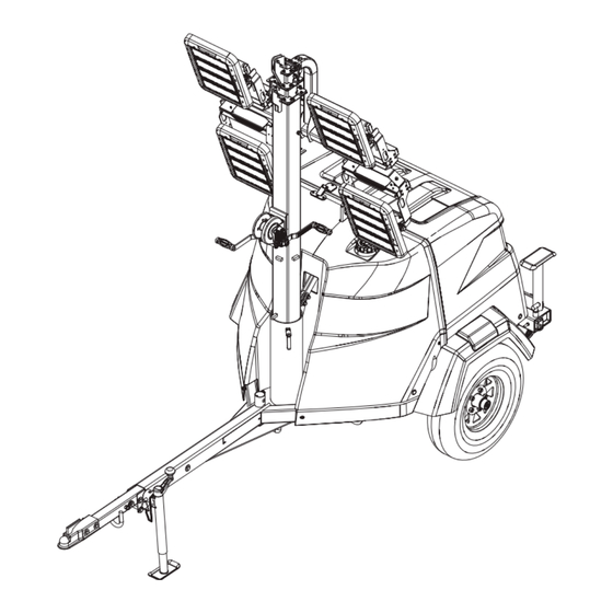
Page 16: Component Locations
General Information Component Locations 008646 Figure 2-10. Component Locations Light fixture (4 locations) Exhaust Fuel fill port Outrigger Jack (2 locations) Grounding stud Outrigger pin (2 locations) Tie-down point M Rear tie-down point (2 locations) Tongue jack Fork pocket (2 locations) Mast rotation knob Tandem tow mount (optional—not shown) Winch... -
Page 17: Control Panel
General Information Control Panel DC CIRCUIT MAST LIGHT CIRCUIT BREAKERS AC CIRCUIT BREAKER BREAKERS CONTROL POWER MAIN CIRCUIT BREAKER ® Standard Power Zone (if equipped) 008707 Figure 2-11. Control Panel Features (A) DC Circuit Breaker (H) Main Circuit Breaker Resets the DC electrical circuit that powers the control 240V/30A breaker which disconnects power from the panel and engine components. -
Page 18: Power Zone-Dla Controller (If Equipped)
General Information Power Zone–DLA Controller (If Equipped) The Power Zone–DLA is an AUTO start controller that engine shuts down automatically and the LCD window monitors the unit and indicates operational status and shows the fault that caused the shutdown. To resume fault conditions. -
Page 19: Operator Screens
General Information Operator Screens Mast Operation Screen Figure 2-15. Allows the operator to raise or lower Figure 2-13. The operator screens display the most the mast. relevant and critical information needed to properly configure and use the unit. From these six screens, the operator can access information necessary to operate the unit under normal conditions. - Page 20 General Information Lights Screen Generator Screen Figure 2-17. Allows the operator to turn the lights on Figure 2-19. The Generator screen displays the and off. Refer to Light Operation (Key Switch Models) average line voltage, frequency (in Hertz), and power for more information.
- Page 21 General Information Figure 2-21. The Scheduler screen allows the Proceed as follows to enter the navigation menu: operator to program specific times for lights to turn on 1. Press both the ↑ and ↓ buttons simultaneously. and off. Once programmed, the Scheduler will start the 2.
- Page 22 General Information Electrical trips stop the generator in a controlled Maintenance Screen • manner. On initiation of the electrical trip condition, Figure 2-25. Maintenance screen ( ) displays the controller de-energizes all the outputs, includ- alarms for servicing the fuel filter, oil filter, and air filter. ing the lights, to remove the load from the genera- tor.
- Page 23 General Information About Screen Figure 2-27. The About ( ) screen contains information about the controller such as the controller’s date and time, the product and USB identification number, and the application and engine version. 003783 Figure 2-27. About Screen Owner’s Manual for Mobile Light Tower...
- Page 24 General Information This page intentionally left blank. Owner’s Manual for Mobile Light Tower...
-
Page 25: Section 3: Operation
Section 3: Operation Unit Setup DETAIL B DETAIL C DETAIL D 1” DETAIL E 010619 Figure 3-1. Setup Components 2. Place the unit on firm ground that is relatively flat DANGER (less than 5° slope). NOTE: Use the bubble levels (H) to level the unit. High Voltage. -
Page 26: Raising The Mast-Manual Winch
Operation 7. See Detail E. Rotate each jack handle clockwise to the mast rotation knob to secure the mast in start leveling the trailer. Adjust all three jacks by position. rotating their handles clockwise until they are firmly 4. Using both hands, rotate the winch (B) to slowly in contact with the ground. -
Page 27: Raising The Mast-Electric Winch (If Equipped)
Operation 1. Set up and level the unit. See Unit Setup. Raising the Mast—Electric Winch (If Equipped) DANGER Electrocution. DO NOT use the unit if electrical cord is cut or worn through. Doing so will result in death or serious injury. (000263a) WARNING Tipping hazard. -
Page 28: Raising The Mast-Power Zone-Dla (If Equipped)
Operation is extending at the top sections of the mast. Stop 3. See Figure 3-5. Press the up/down arrows (A) until extending the mast when the colored mark (C) on the mast screen is shown. the second mast section is visible as seen in Detail IMPORTANT NOTE: A limit switch on the main mast section will disconnect power to the electric winch to prevent overextending the mast. -
Page 29: Prestart Checklist
Operation Prestart Checklist Starting the Unit (Key Switch Before starting the unit, all items in the prestart checklist Models) must be completed. This checklist applies to both manual and remote starting of the unit. CAUTION WARNING Equipment Damage. Do not continuously crank engine for more than ten seconds. -
Page 30: Preparing For Start-Up (Power Zone-Dla)
Operation 3. See Figure 3-8. Turn the key to the right START MANUAL mode is used for on-demand control of • position and hold it (10 seconds maximum) until the lights and convenience receptacles. the engine cranks and starts running. 009952 Figure 3-8. -
Page 31: Manually Starting The Unit
Operation Light Operation (Key Switch Models) WARNING Burn hazard. Never operate lights with a damaged or missing lens cover. Lamps are hot and pressurized while in use. Unprotected lamps can shatter, causing severe injury. (000277) 1. Verify the unit is ON and running smoothly. 2. -
Page 32: Engine Derating
Operation Dusk to Dawn Sensor (Power Zone–DLA) (If Equipped) Figure 3-13. If equipped with the Power Zone-DLA controller, this unit includes “dusk dawn” nightwatchman sensor (A) to detect the surrounding light level, automatically starting the engine and turning the lights on at dusk. The engine will run and the lights will remain illuminated until dawn. -
Page 33: Shutting Down The Unit
Operation 5. After the unit shuts down, switch the control power switch OFF (O). NOTE: Disconnect the battery if the unit will be stored for an extended period. Refer to the engine operator’s manual for additional extended storage procedures. Automatic Shutdown This unit is equipped with a low oil pressure and high coolant temperature automatic shutdown system. -
Page 34: Lowering The Mast-Electric Winch (If Equipped)
Operation aligned and the metal stop tabs are touching. Manually Lowering the Mast c. Tighten the mast rotation knob. IMPORTANT NOTE: Do not use this procedure unless it is absolutely necessary. Frequent use of Lowering the Mast—Electric this procedure could damage the motor shaft. Winch (If Equipped) 1. -
Page 35: Positive Air Shutdown (Pas) (If Equipped)
WARNING dicular to the pipe centerline. If valve does not close, con- tact Generac Mobile Technical Support. Personal Injury. Stop immediately if the mast hangs up or the winch cable develops slack. Excess slack... -
Page 36: Telemetry (If Equipped)
Operation Connect the towing chains to the tie down locations Towing the Unit • (C). Once the engine is shut down and the mast and lights are Avoid sharp turns when towing. Do not cross any correctly stowed, proceed as follows to prepare the unit •... -
Page 37: Lifting The Unit
Operation Lifting the Unit Proceed as follows to prepare the unit for lifting: 1. Verify the equipment being used to lift the unit is in good condition and has sufficient capacity. For approximate weights, refer to Specifications. 2. Close and lock all hoods and doors. 3. - Page 38 Operation This page intentionally left blank. Owner’s Manual for Mobile Light Tower...
-
Page 39: Section 4: Maintenance
Regular maintenance will improve performance and Verify winch cables are in good condition and • extend engine/equipment life. Generac Mobile, LLC rec- centered on each pulley. DO NOT use a cable that ommends that all maintenance work be performed by a is kinked or starting to unravel. -
Page 40: Basic Maintenance Schedule
Drain residual water from fuel filter Generac Mobile recommends oil change intervals on the MLT6SMDS equipped with the Mitsubishi L3E Tier 4 engine be extended to 1,000 hours after initial break-in. The engine comes from the factory with a larger sump that holds 5.5 qts (5.2 L) of engine oil. - Page 41 Replace the air cleaner element yearly, or after six cleanings, whichever occurs first. Generac Mobile recommends that oil change intervals on the MLT6SKDS equipped with the Kubota engine be extended to 750 hours after initial break-in. The engine comes from the factory with a larger sump that holds 5.5 qts (5.2 L) of engine oil.
-
Page 42: Resetting The Maintenance Alarms (If Equipped)
Maintenance 2. Verify the cable and cable attachments are not Resetting the Maintenance damaged. Contact Generac Mobile to order a Alarms (If Equipped) replacement cable if necessary. The Power Zone-DLA controller will display a warning 3. Referring to the “Lift / Let Down” decal on the... -
Page 43: Winch Mechanical Brake
Valvoline W615 or equivalent. rock the wheel. If further assistance is required, contact Figure 4-2. Proceed as follows to lubricate the Generac Mobile Technical Service at 1-800-926-9768. wheel bearings: Jack Maintenance Before each use, inspect each jack foot for damage and remove any mud or debris. - Page 44 Maintenance This page intentionally left blank. Owner’s Manual for Mobile Light Tower...
-
Page 45: Section 5: Troubleshooting
Verify fuel pump operation. Restricted air filter Inspect air filter for blockage. Refer to OEM engine operator’s manual for additional information. PAS engaged Verify PAS is off. If problems persist, contact Generac Mobile at 1-800-926-9768 for assistance. Owner’s Manual for Mobile Light Tower... -
Page 46: Troubleshooting The Lights
Troubleshooting Troubleshooting the Lights Only a qualified electrician should troubleshoot or repair electrical problems occurring in this equipment. Contact Generac Mobile Technical Service at 1-800-926-9768 for assistance if you have any questions, or if problems persist. WARNING WARNING Burn hazard. Lamps become extremely hot Electrocution. -
Page 47: Section 6: Wiring Diagrams
Section 6: Wiring Diagrams Mast Junction Box Wiring and Light Connections 008713 Owner’s Manual for Mobile Light Tower... -
Page 48: Ac Wiring-Mlt6Skds
Wiring Diagrams AC Wiring—MLT6SKDS 10000036247_B_02.07.19 Owner’s Manual for Mobile Light Tower... -
Page 49: Ac Wiring-Mlt6Smds
Wiring Diagrams AC Wiring—MLT6SMDS 10000035916_E_01.29.19 Owner’s Manual for Mobile Light Tower... -
Page 50: Ac Wiring-Mlt6Smds With Power Zone (If Equipped)
Wiring Diagrams AC Wiring—MLT6SMDS With Power Zone (If Equipped) 10000037756_D_02.01.19 Owner’s Manual for Mobile Light Tower... -
Page 51: Ac Wiring-Mlt6Skds With Power Zone (If Equipped)
Wiring Diagrams AC Wiring—MLT6SKDS With Power Zone (If Equipped) 10000037767_C_02.01.19 Owner’s Manual for Mobile Light Tower... -
Page 52: Dc Wiring-Mlt6Smds
Wiring Diagrams DC Wiring—MLT6SMDS 10000044651_A_11.09.18 Owner’s Manual for Mobile Light Tower... -
Page 53: Dc Wiring-Mlt6Smds With Power Zone (If Equipped)
Wiring Diagrams DC Wiring—MLT6SMDS With Power Zone (If Equipped) 10000044408_B_11.09.18 Owner’s Manual for Mobile Light Tower... -
Page 54: Dc Wiring-Mlt6Skds
Wiring Diagrams DC Wiring—MLT6SKDS 90509_E_6.27.16 Owner’s Manual for Mobile Light Tower... -
Page 55: Dc Wiring-Mlt6Skds With Power Zone (If Equipped)
Wiring Diagrams DC Wiring—MLT6SKDS with Power Zone (If Equipped) 10000037773_C_05.25.18 Owner’s Manual for Mobile Light Tower... -
Page 56: Dc Wiring-Heated Fuel Filter (If Equipped)-Mlt6Smds
Wiring Diagrams DC Wiring—Heated Fuel Filter (If Equipped)—MLT6SMDS 90602_B_02.26.19 Owner’s Manual for Mobile Light Tower... -
Page 57: Dc Wiring-Heated Fuel Filter (If Equipped)-Mlt6Skds
Wiring Diagrams DC Wiring—Heated Fuel Filter (If Equipped)—MLT6SKDS 90601_ORG_03.17.15 Owner’s Manual for Mobile Light Tower... -
Page 58: Dc Wiring-Electric Winch (If Equipped) With Standard Controller
Wiring Diagrams DC Wiring—Electric Winch (If Equipped) with Standard Controller TOP SWITCH (DOWN STOP) BOTTOM SWITCH (UP STOP) WINCH TIME DELAY RELAY SWITCH 1 CONTACTOR 1 BK/WT BK/VI BK/VI BK/VI DOWN BATTERY 90596_A_07.19.16 Owner’s Manual for Mobile Light Tower... -
Page 59: Trailer Lights
Wiring Diagrams Trailer Lights SPADE VI/YL SPADE BK/WT SPADE SPADE SPADE SPLICE SPADE 90520_D_08.27.14 Owner’s Manual for Mobile Light Tower... -
Page 60: Dc Wiring-Electric Winch With Power Zone Controller (If Equipped)
Wiring Diagrams DC Wiring—Electric Winch with Power Zone Controller (If Equipped) 90615_A_12.15.15 Owner’s Manual for Mobile Light Tower... - Page 61 Wiring Diagrams This page intentionally left blank. Owner’s Manual for Mobile Light Tower...
- Page 62 Section 6 - This page intentionally left blank.
- Page 64 ©2020 Generac Mobile Products, LLC All rights reserved. Generac Mobile Products, LLC Specifications are subject to change without notice. 215 Power Drive, Berlin, WI 54923 No reproduction allowed in any form without prior written GeneracMobileProducts.com │800-926-9768 │920-361-4442 consent from Generac Mobile Products, LLC.
Need help?
Do you have a question about the MLT6SMDS and is the answer not in the manual?
Questions and answers