Table of Contents
Advertisement
Quick Links
Advertisement
Table of Contents

Related Manuals for Samlexpower SA-1000K Series


Summary of Contents for Samlexpower SA-1000K Series
- Page 1 SA-1000K & SA-3000K Series Pure Sine Wave Inverter User’s Manual...
-
Page 2: Table Of Contents
Table of Contents 1. Important Safety Information.……………………………………………… General Safety Precautions…………………………………………… Battery Precautions………………………..………………………….. 2. Features………………………………………………………………………... Application………………………………………………………………. Electrical Performance………………………………………………… Mechanical Drawings………………………………………………….. 3. Introduction…………………………………………………………………… Front Panel operation….……………………………………………... 7~10 Rear Panel operation.………………………………………………… 11~12 Protections Features…………………………………………………… Installation………………………………………………………………. Making DC Wiring Connections ……………………………………... 14~16 AC Safety Grounding………………………………………………….. Inverter Operation………………………………………………………... -
Page 3: Important Safety Information
1. Important Safety Instructions WARNING! Before using the Inverter, read and save the safety instructions. 1-1. General Safety Precautions 1-1-1. Do not expose the Inverter to rain, snow, spray, bilge or dust. To reduce risk of hazard, do not cover or obstruct the ventilation openings. -
Page 4: Features
2. Features Pure sine wave output (THD < 3%) Output frequency:50 / 60Hz switch selections Input & output fully isolated design Power Saving Mode to conserve energy High efficiency 89~94% Driving highly reactive & capacitive loads at start moment Tri-Color indicators show input voltage & output load level Loading controlled cooling fan Advanced microprocessor Protection:Input low voltage... -
Page 5: Electrical Performance
2-2. Electrical Performance Specification Model No. Item SA-1000K-112 SA-1000K-124 Continuous Output Power 1000W Maximum Output Power 1100W Surge Rating (Max) 2000W Input voltage 100 / 110 / 120V +/- 5% Output Voltage Frequency 50 / 60Hz +/- 0.05% (Switch Selectable) Output Waveform Pure Sine Wave ( THD <... - Page 6 Model No. Specification Item SA-3000K-112 SA-3000K-124 Continuous Output Power 3000W Maximum Output Power 3300W Surge Rating (Max) 6000W Input voltage 100 / 110 / 120V +/- 5% Output Voltage Frequency 50 / 60Hz +/- 0.05% (Switch Selectable) Output Waveform Pure Sine Wave ( THD < 3% ) Efficiency (full load) Max.
-
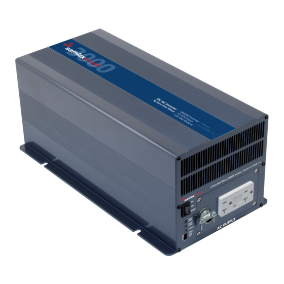
Page 7: Mechanical Drawings
2-3. Mechanical Drawings SA-1000K 154.00 [6.06] PURE SINE WAVE INVERTER 1000W INPUT LEVEL LOAD LEVEL STATUS REMOTE FREQ. PWR. SAV. AC OUTPUT 182.00[7.17] 191.00[7.52]... - Page 8 177.00 [6.97] PURE SINE WAVE INVERTER REMO. INPUT LEVEL LOAD LEVEL STATUS FREQ. PWR. SAV. AC OUTPUT 209.00 [8.23]...
-
Page 9: Introduction
3. Introduction This power inverter series is one of the most advanced line of mobile AC power systems. To get the most effective power inverter, it must be installed and used properly. Please read the instructions of this manual before you install and operate this model. - Page 10 3-1-3. Input Level:Display Input Voltages LED Status DC 12V DC 24V RED Slow Blink 10.3~10.6 20.5~21.2 10.6~11.0 21.2~21.8 ORANGE 11.0~12.1 21.8~24.1 GREEN 12.1~14.2 24.1~28.6 ORANGE Blink 14.2~15.0 28.6~30.0 OVER RED Blink 15.0 30.0 3-1-4. Load Level:Display AC Loads (Watts) LED status DARK GREEN ORANGE...
- Page 11 3-1-6. Status:Display Power & Fault Status Green LED LED Signal Status Solid Power OK Slow Blink Power Saving Red LED LED Signal Status Fast Blink Slow Blink Intermittent Blink Solid 3-1-7. Power Saving Mode: Power Saving Mode is adjustable and set by the Dip Switches, S1, S2 and S3 on the front panel.
- Page 12 3-1-8. AC outlets (available): North America (GFCI) NEMA 5-20R Continental European NEMA 5-15R Australia / New Zealand United Kingdom Universal IEC-1 HARD WIRE IEC-2...
-
Page 13: Rear Panel Operation
3-2. Rear Panel Operations DC INPUT POS(+) NEG(-) SA-1000K REMOTE PORT CHASSIS GROUND REVERSE POLARITY WILL DAMAGE UNIT SA-3000K POS(+) DC INPUT NEG(-) REMOTE WARNING: PORT REVERSE POLARITY WILL DAMAGE UNIT CHASSIS SHOCK HAZARD. GROUND DO NOT OPEN. NO USER SERVICEABLE PARTS INSIDE. -
Page 14: Protections Features
Connect DC input terminal to 12V / 24V battery or the other power sources. 【+】represents positive, and【-】represents negative. Reverse polarity connection will blow the internal fuse and may damage the inverter permanently. DC Input Voltage Model Minimum Maximum 12 V 10.5 15.0 24 V... -
Page 15: Installation
3-4. Installation The power inverter should be installed in an environment that meets the following requirements: 3-4-1. Dry – Do not allow water to drip on or enter into the inverter. 3-4-2. Cool – Ambient air temperature should be between 0℃ and 40℃, the cooler the better. -
Page 16: Making Dc Wiring Connections
3-5. DC Wiring Connections Follow this procedure to connect the battery cables to the DC input terminals of the Inverter. The cables should be as short as possible (less than 10 feet / 3 meters ideally) and large enough to handle the required current in accordance with the electrical codes or regulations applicable to the installation. - Page 17 3-5-1. Connect the cables to the power input terminals on the rear panel of the inverter. The red terminal is represents positive (+) and black terminal represents negative (-). Insert the cables into the terminals and tighten the screw to clamp the wires securely. WARNING! Ensure all the DC connections are tight (torque to 9 –...
- Page 18 SA-1000K DC INPUT POS(+) NEG(-) REMOTE PORT CHASSIS GROUND INLINE FUSE BATTERY Battery to inverter cable connection SA-3000K POS(+) DC INPUT NEG(-) REMOTE WARNING: PORT REVERSE POLARITY WILL DAMAGE UNIT CHASSIS SHOCK HAZARD. GROUND DO NOT OPEN. NO USER SERVICEABLE PARTS INSIDE.
-
Page 19: Ac Safety Grounding
3-6. AC Safety Grounding The AC output ground wire should go to the grounding point for your loads (for example, a distribution panel ground bus ). 3-6-1. Neutral Grounding (GFCI’S): 3-6-1-1. 120V models: The neutral conductor of the AC output circuit of the Inverter is automatically connected to the safety ground during inverter operation. -
Page 20: Inverter Operation
3-7. Inverter Operation To operate the power inverter, use the ON / OFF switch on the Front panel to turn the power on. Then the power inverter is ready to deliver AC power to your loads. If there is several loads use, turn them on separately after the inverter is “ON”... -
Page 21: Troubleshooting Guide
4. Troubleshooting WARNING! Do not open or disassemble the Inverter. Attempting to service the unit yourself may cause the risk of electrical shock or fire. Problems and Symptoms Possible Cause Solutions “No AC Power Output” STATUS illuminates the red LED a. -
Page 22: Maintenance
5. Maintenance To keep your inverter operating properly, there is very little maintenance required. You should clean the exterior periodically with a damp cloth to prevent accumulation of dust and dirt. At the same time, tighten the screws on the DC input terminals. - Page 23 Samlex America Inc. 110-17 Fawcett Road, Coquitlam, BC, V3K 6V2 Canada Toll free phone: 1-800-561-5885 Toll free fax: 1-888-814-5210 General Inquiries: samlex@samlexamerica.com WWW: http://www.samlexamerica.com 034_2009_SA-1000K_SA-3000K_Manual_Dec2009...
Need help?
Do you have a question about the SA-1000K Series and is the answer not in the manual?
Questions and answers