
Subscribe to Our Youtube Channel
Related Manuals for Samlexpower SAM-1000-12


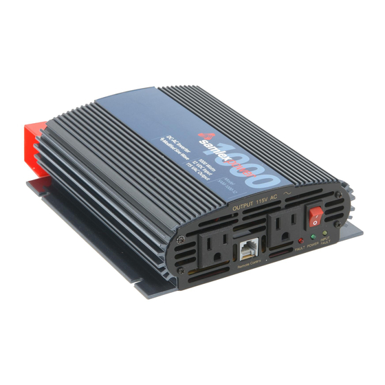
Summary of Contents for Samlexpower SAM-1000-12
- Page 1 SAM Series owner's Please read this manual before Manual Power installing your Inverters inverter SAM-1000-12 SAM-1500-12 SAM-2000-12 SAM-3000-12...
-
Page 2: Table Of Contents
MANUAL | Index Section 1: Important Safety Instructions ..............1 Section 2: Description ..................3 Features ..................... 3 Principle of Operation ................4 Section 3: Product Layout ..................6 Section 4: Installation ..................... 7 Section 5: Operation ................... 18 Section 6: Protections, Monitoring &... -
Page 3: Important Safety Instructions
SECTION 1 | Safety important Safety inStructionS This manual contains important information regarding safety, operation, maintenance and storage of this product. before use, read and understand all cautions, warnings, in- structions and product labels, plus your vehicle’s battery manufacturer’s guidelines. failure to do so could result in injury and / or property damage. - Page 4 SECTION 1 | Safety caution! 1. The metal chassis of the inverter and the Grounding Terminal of the NeMA5-15r outlet(s) are internally bonded (connected) to the Negative DC Input Terminal on the inverter. In a vehicle / boat, the Negative Terminal of the battery is bonded to vehicle chassis / boat’s hull. Hence, the metal chassis of the inverter and the AC loads will be automatically grounded (bonded to the vehicle chassis / boat’s hull).
-
Page 5: Description
SECTION 2 | Description, Features & Principle of Operation info for additional technical and operational information on inverters, battery chargers and related topics, please refer to www.samlexamerica.com under "Support" and view "Application Notes" and/or "White Papers" section. Description The inverter converts 12 VDC voltage from battery or from other suitable 12 VDC source to 115V, 60 Hz AC voltage. The waveform of the of the AC output voltage is Modified Sine Wave. features • High peak efficiency of 90% • Very high power to weight ratio - compact and light weight... -
Page 6: Principle Of Operation
Cooling is carried out by convection and by forced air circulation by load-controlled fan. The fan will normally be off and will be switched oN automatically at the following loads: SAM-1000-12 28 to 32 Watts SAM-1500-12, SAM-2000-12 & SAM-3000-12 90 to 110 Watts... - Page 7 SECTION 2 | Description, Features & Principle of Operation The output waveform of the inverter is a Modified Sine Wave. In a Modified Sine Wave, the voltage waveform consists of rectangular pulses that approximate sine wave pulses of a Pure Sine Wave. The voltage rises and falls abruptly at a particular phase angle and sits at 0 Volts for some time before changing its polarity. In a Pure Sine Wave, the voltage rises and falls smoothly with respect to phase angle and the voltage changes its polarity instantly when it crosses 0 Volts.
-
Page 8: Product Layout
SECTION 3 | Layout Fig. 3.1 – SAM-1000-12 Fig. 3.2 – SAM-1500-12 Fig 3.3 – SAM-2000-12, SAM-3000-12 LeGenD 1. oN/off Switch 7. RED LED - "Fault" 2. NeMA5-15r AC outlet 8. Cooling Air Intake Slots 3. Modular Jack for remote Control 9. opening for fan Air Discharge SAM-rC (optional) 10. -
Page 9: Installation
SECTION 4 | Installation typical installation Diagram BACK OF INVERTER FRONT OF INVERTER – AC Load Fuse Remote Control – SAM-RC (optional) 12V Battery Vehicle Ground or Earth Ground Fig 4.0. Typical Installation Diagram (front & back) Safety of installation Please read safety instructions on pages 1-2 before commencing installation. -
Page 10: General Information
SECTION 4 | Installation Input Terminal side. Keep the areas surrounding the inverter clear by at least 10 cm to ensure free air circulation around the unit. ensure that the ventilation slots and fan opening on the sides are not blocked. Do not place items on or over the inverter during operation. mounting orientation Two (2) flanges on the bottom with 2 mounting slots each are provided for mounting. -
Page 11: Series Connection
Dc input current required by inverter = power consumed by the ac Load in Watts ÷ 10. DC input currents at Continuous rated Power output are shown (Table 4.1 below): table 4.1 Dc input current model rated input current SAM-1000-12 100A SAM-1500-12 150A SAM-2000-12 200A... -
Page 12: Parallel Connection
SECTION 4 | Installation When two or more batteries are connected in series, their voltages add up but their Ah capacity remains the same. fig. 4.2 above shows 4 pieces of 6V, 200 Ah batteries connect- ed in series to form a battery bank of 24V with a capacity of 200 Ah. The Positive terminal of battery 4 becomes the Positive terminal of the 24V bank. - Page 13 SECTION 4 | Installation figure 4.4 above shows a series – parallel connection consisting of four 6V, 200 Ah batteries to form a 12V, 400 Ah battery bank. Two 6V, 200 Ah batteries, batteries 1 and 2 are con- nected in series to form a 12V, 200 Ah battery (String 1). Similarly, two 6V, 200 Ah batteries, batteries 3 and 4 are connected in series to form a 12V, 200 Ah battery (String 2).
- Page 14 SECTION 4 | Installation An example of this calculation for a 12V inverter is given below: Let us say that the total continuous ac Watts delivered by the 12V inverter = 1500W. Then, using Formula 2 above, the DC current to be delivered by the 12V batteries = 1500W ÷10 = 150 Amperes. next, the energy required by the load in ampere Hours (ah) is determined: For example, if the load is to operate for 3 Hours, then as per Formula 3 above, the energy to be delivered by the 12V batteries = 150 Amperes × 3 Hours = 450 Ampere Hours (Ah). finally, as per rule of thumb at formula 4, the ah capacity of the batteries should be twice the energy required by the load in ah = 450 Ah x 2 = 900 Ah.
- Page 15 + Drop Dc input cable Size fuse fuse fuse Kit model no. current (ampacity) Size 3 ft. 6 ft. 10 ft. (optional) (optional) SAM-1000-12 100A AWG#4 100 to 1.2% 2.4% 4.0% DC-FA-100 DC-1000-KIT (160A) 150A SAM-1500-12 150A AWG#2 200A 1.2% 2.3%...
- Page 16 (2, fig 3.2) each power (rated output outlet with 15a Breaker model no. the inverter power ÷ 115Vac) (2, figs 3.1, 3.2) (4, fig 3.2) 8.7A SAM-1000-12 1000 VA SAM-1500-12 1500VA 13.0A SAM-2000-12 2000VA 17.4A SAM-3000-12 3000VA 26.0A 14 | SAMLEX AMERICA INC.
- Page 17 SECTION 4 | Installation noteS for taBLe 4.3 1. Power shown in the Table above is the Apparent Power in Volt Amps (VA). Active Power in Watts = Ap- parent Power in VA x Power Factor of the AC load. For resistive type of AC loads, the Power Factor is 1 and for these types of loads, Apparent Power in “VA” = Active Power in “Watts”. Power ratings shown in the Specifications on page 24 are applicable for Resistive Load and hence, Watts = VA 2. Each NEMA5-15R outlet is rated at maximum current capacity of 15A and power of 1725VA at 115VAC 3. CAUTION! for SAM-2000-12 and SAM-3000-12, the full rated power cannot be drawn from 1 NeMA5-15r outlet as each outlet is rated for only 15A (1725VA) and is protected by 15A breaker. If a single load rated at >...
- Page 18 SECTION 4 | Installation taBLe 4.4: inVerter SiZinG factor type of Device or appliance inverter Sizing factor Air Conditioner / Refrigerator / Freezer (Compressor based) Air Compressor Sump Pump / Well Pump / Submersible Pump Dishwasher / Clothes Washer Microwave (where rated output power is the cooking power) Furnace Fan Industrial Motor Portable Kerosene / Diesel Fuel Heater...
- Page 19 SECTION 4 | Installation Shield the DC side wires with metal sheathing / copper foil /braiding: - Use coaxial shielded cable for all antenna inputs (instead of 300 ohm twin leads) - Use high quality shielded cables to attach audio and video devices to one another. Limit operation of other high power loads when operating audio/video equipment. Buzzing Sound in audio Systems Some inexpensive sound stereo systems and “Boom Boxes” may emit a buzzing sound from their speakers when operated from this unit.
-
Page 20: Operation
SECTION 5 | Operation connecting Loads, Switching on & Switching off connecting Loads 1. Make sure that single load or the combined load requirement of your equipment does not exceed the inverter's output rating. 2. Switch off the inverter. 3. Switch off the load. 4. Plug the cord(s) from the load(s) into the AC receptacle(s) of the inverter 5. -
Page 21: Rated Versus Actual Current Draw Of Equipment
SECTION 5 | Operation If the oN/off Switch on the inverter is left in oN position, the inverter cannot be switched off using remote Control. The remote Control will, however, continue to display the Status of operation. note: When optional remote Control SAM-rC is used to switch off the unit, the GREEN LED "Power" (6-Fig 3.1, 3.2 & 3.3) takes 30 to 45 secs to extinguish if there is no load connected to the inverter. If a load is present, the LED will extinguish within a very short time. -
Page 22: Protections Monitoring & Trouble-Shooting
SECTION 6 | Protections Monitoring & Trouble-Shooting note: please refer to table 6.1 for status of monitoring LeDs and Buzzer for various protections / operational conditions explained below. over temperature protection The unit is cooled by load-controlled fan. In case the fan fails or if the cooling is inad- equate due to higher ambient temperature or restricted airflow, the temperature of hot spot inside the inverter will exceed the safe temperature threshold of 88°C to 115°C and the unit will automatically shut down. Yellow LED "Input Fault" will be ON & Green... - Page 23 SECTION 6 | Protections Monitoring & Trouble-Shooting Low input Voltage Buzzer alarm A buzzer alarm will sound when the voltage at the input terminals of the inverter drops to 10.8V ± 0.3V. This is an indication that either the battery terminal voltage has dropped due to its discharged condition and needs to be re-charged or there is an excessive volt- age drop across the wires connecting the inverter to the battery (due to use of thinner and longer length of wires that will produce higher voltage drop at higher loads or due...
- Page 24 SECTION 6 | Protections Monitoring & Trouble-Shooting down. Red LED "Overload" will be ON and Green LED "Power" will also be ON. The unit will latch in shutdown condition. To reset, switch off the oN/off switch, wait for 3 minutes and switch oN again. • Ground fault protection will also operate if the neutral and ground of the ac output of the inverter are connected (bonded) intentionally like in Service entrance / Load center for ac distribution wiring.
- Page 25 SECTION 6 | Protections Monitoring & Trouble-Shooting operating threshold/ Green yeLLoW Buzzer remedy/reset condition/ reason LeD (6, LeD (5, LeD (7, protection power) input fault) fault) No Output Internal hot OFF* Check ambient tempera- due to High spot > 88°C ture, fan and loss of cool Temperature to 115°C...
-
Page 26: Specifications
SECTION 7 | Specifications INVERTER PARAMETER SAM-1000-12 SAM-1500-12 SAM-2000-12 SAM-3000-12 input BATTERy SySTEM VOLTAGE 12 VDC 12 VDC 12 VDC 12 VDC NOMINAL INPUT VOLTAGE 12.5 VDC 12.5 VDC 12.5 VDC 12.5 VDC INPUT VOLTAGE RANGE > 10.5 VDC to < 15.0 (± 0.5) VDC... - Page 27 7. SPÉCIFICATIONS PARAMÈTRE ONDULEUR SAM-1000-12 SAM-1500-12 SAM-2000-12 SAM-3000-12 entrÉe TENSION DE SySTèME DE BATTERIE 12 VCC 12 VCC 12 VCC 12 VCC TENSION D'ENTRéE NOMINALE 12,5 VCC 12,5 VCC 12,5 VCC 12,5 VCC PLAGE DE TENSION D'ENTRéE > 10,5 VCC á < 15,0 (± 0.5) VCC COURANT D'ENTRéE à...
-
Page 28: Warranty
SECTION 8 | Warranty 2 year LimiteD Warranty SAM-1000-12, SAM-1500-12, SAM-2000-12 & SAM-3000-12 manufactured by Samlex Amer- ica, Inc. (the “Warrantor“) is warranted to be free from defects in workmanship and ma- terials under normal use and service. The warranty period is 2 years for the United States and Canada, and is in effect from the date of purchase by the user (the “Purchaser“). - Page 29 SECTION 8 | Warranty Garantie Limitee SouS 2 anS SAM-1000-12, SAM-1500-12, SAM-2000-12 et SAM-3000-12 fabriqués par Samlex America, Inc. (le « Garant ») sont garantis être non défectueux dans la conception et dans les ma- tériaux, moyennant une utilisation et un service normaux. La période de garantie est de 2 ans pour les etats-Unis et le Canada, et prend effet le jour de l’achat par l’utilisateur (« l’Acheteur »). La garantie hors des etats Unis et du Canada est limitée à 6 mois. Pour une réclamation concernant la garantie, l’Acheteur devra contacter le point de vente ou l’achat a été...
- Page 30 Notes 28 | SAMLEX AMERICA INC.
- Page 31 Notes SAMLEX AMERICA INC. | 29...
- Page 32 Contact Information Toll Free Numbers Ph: 800 561 5885 Fax: 888 814 5210 Local Numbers Ph: 604 525 3836 Fax: 604 525 5221 Website www.samlexamerica.com USA Shipping Warehouse Kent WA Canadian Shipping Warehouse Delta BC Email purchase orders to orders@samlexamerica.com 11002-SAM-1000-1500-2000-3000-0614...
Need help?
Do you have a question about the SAM-1000-12 and is the answer not in the manual?
Questions and answers