Table of Contents
Advertisement
Quick Links
Advertisement
Table of Contents

Related Manuals for Data Translation DT330 Series


Summary of Contents for Data Translation DT330 Series
- Page 1 (217) 352-9330 | Click HERE Find the Measurement Computing / Data Translation DT334 at our website:...
- Page 2 Title Page UM-17416-P DT330 Series User’s Manual Artisan Technology Group - Quality Instrumentation ... Guaranteed | (888) 88-SOURCE | www.artisantg.com...
- Page 3 Copyright Page Trademark and Copyright Information Measurement Computing Corporation, InstaCal, Universal Library, and the Measurement Computing logo are either trademarks or registered trademarks of Measurement Computing Corporation. Refer to the Copyrights & Trademarks section on mccdaq.com/legal for more information about Measurement Computing trademarks. Other product and company names mentioned herein are trademarks or trade names of their respective companies.
- Page 4 Changes or modifications to this equipment not expressly approved by Data Translation could void your authority to operate the equipment under Part 15 of the FCC Rules.
- Page 5 Artisan Technology Group - Quality Instrumentation ... Guaranteed | (888) 88-SOURCE | www.artisantg.com...
-
Page 6: Table Of Contents
Table of Contents Table of Contents About this Manual ............9 Intended Audience. - Page 7 Calibrating a DT330 Series Board ........
- Page 8 Contents Chapter 8: Troubleshooting ..........77 General Checklist .
- Page 9 Contents Artisan Technology Group - Quality Instrumentation ... Guaranteed | (888) 88-SOURCE | www.artisantg.com...
-
Page 10: About This Manual
This manual describes how to set up and install a DT330 Series board and related software, attach a screw terminal panel or paddle board to a DT330 Series board, wire signals to a screw terminal panel, and verify the board’s operation using the Quick DataAcq application. -
Page 11: Conventions Used In This Manual
• Items that you select or type are shown in bold. Related Information Refer to the following documents for more information on using the DT330 Series boards: • Measure Foundry Manual (UM-19298) and online help. These documents describe how to use Measure Foundry™... -
Page 12: Where To Get Help
(Revision 2.1, June 1, 1995). • Windows XP, Windows Vista, or Windows 7 documentation. Where To Get Help Should you run into problems installing or using a DT330 Series board, our Technical Support Department is available to provide technical assistance. Refer to Chapter 8... - Page 13 About this Manual Artisan Technology Group - Quality Instrumentation ... Guaranteed | (888) 88-SOURCE | www.artisantg.com...
-
Page 14: Chapter 1: Overview
Overview Features ..............Supported Software . -
Page 15: Features
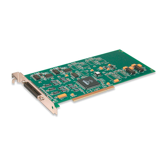
The DT330 Series is a family of low-cost, analog output and digital I/O boards for the PCI bus. The DT330 Series consists of the following boards: DT331, DT332, DT333, DT334, DT335, and DT335-50. All DT330 Series boards share the following major features: •... -
Page 16: Supported Software
Overview Supported Software The following software is available for use with the DT330 Series boards and is provided on the Data Acquisition OMNI CD: • DT330 Series Device Driver – The device driver is installed automatically when you install the software from the Data Acquisition OMNI CD. You need the device driver to use the DT330 Series board with any of the supported software packages or utilities. -
Page 17: Accessories
EP036 cables. • EP305 cable – A 2-meter, twisted-pair, shielded cable that connects the 68-pin connector (J1) on all DT330 Series boards except the DT335-50 to the J1 connector on the STP68 or STP68-DIN screw terminal panel. • EP035-2 cable – A 1-meter, 50-conductor flat ribbon cable assembly with a female header that connects the 50-pin connector (J1) on the DT758-C screw terminal panel to the 50-pin connector (J1) on the DT335-50 board. -
Page 18: Getting Started Procedure
Overview Getting Started Procedure The flow diagram shown in Figure 1 illustrates the steps needed to get started using a DT330 Series board. This diagram is repeated in each getting started chapter; the shaded area in the diagram shows you where you are in the getting started procedure. Install the Board and Load the Device Driver (see Chapter 2 starting on page... - Page 19 Chapter 1 Artisan Technology Group - Quality Instrumentation ... Guaranteed | (888) 88-SOURCE | www.artisantg.com...
-
Page 20: Part 1: Getting Started
Part 1: Getting Started Artisan Technology Group - Quality Instrumentation ... Guaranteed | (888) 88-SOURCE | www.artisantg.com... - Page 21 Artisan Technology Group - Quality Instrumentation ... Guaranteed | (888) 88-SOURCE | www.artisantg.com...
-
Page 22: Chapter 2: Installing The Board And Loading The Device Driver
Installing the Board and Loading the Device Driver Unpacking ..............Setting up the Computer . - Page 23 Chapter 4 starting on page Note: All DT330 Series boards are factory-calibrated and require no further adjustment prior to installation. If you are using the DT330 Series board and decide later to recalibrate it, refer to Chapter 7 starting on page 71 for instructions.
-
Page 24: Unpacking
• DT330 Series data acquisition board • Data Acquisition OMNI CD If an item is missing or damaged, contact Data Translation. If you are in the United States, call the Customer Service Department at (508) 946-5100 An application engineer will guide you through the appropriate steps for replacing missing or damaged items. -
Page 25: Setting Up The Computer
To set up the computer, do the following: 1. Install the software from the Data Acquisition OMNI CD or Data Translation web site. Note: If you are using Windows 7, you must install the device driver before installing the board in the computer. -
Page 26: Setting Up An Expansion Slot
Installing the Board and Loading the Device Driver Setting up an Expansion Slot Once you have set up the computer, set up an expansion slot by doing the following: 1. Select a 32-bit or 64-bit PCI expansion slot. PCI slots are shorter than ISA or EISA slots and are usually white or ivory. Commonly, three PCI slots (one of which may be a shared ISA/PCI slot) are available. -
Page 27: Inserting The Board Into The Computer
Chapter 2 Inserting the Board into the Computer Once you have set up an expansion slot, do the following to insert the DT330 Series board into the computer: 1. Discharge any static electricity by holding the wrapped board in one hand while placing your other hand firmly on a metal portion of the computer chassis. -
Page 28: Loading The Device Driver
8. Open the Control Panel. 9. Double-click the Open Layers Control Panel icon. 10. Select the DT330 Series board to configure, and then click Advanced. 11. Select the appropriate boxes to enable interrupts for lines (bits) 0 to 7 on digital port D. -
Page 29: Windows 7
4. Open the Control Panel. 5. Double-click the Open Layers Control Panel icon. 6. Select the DT330 Series board to configure, and then click Advanced. 7. Select the appropriate boxes to enable interrupts for lines (bits) 0 to 7 on digital port D. -
Page 30: Chapter 3: Wiring Signals
Wiring Signals Before Wiring ..............Connecting Analog Output Signals. - Page 31 Chapter 3 Install the Board and Load the Device Driver (see Chapter 2 starting on page Wire Signals (this chapter) Verify the Operation of the Board (see Chapter 4 starting on page Artisan Technology Group - Quality Instrumentation ... Guaranteed | (888) 88-SOURCE | www.artisantg.com...
-
Page 32: Before Wiring
The DT331, DT332, DT333, DT334, and DT335 boards provide a 68-pin user connector. To make wiring easier, you can use the EP305 cable from Data Translation to connect an STP68 or STP68-DIN screw terminal panel to the 68-pin connector of one of these boards. You can then wire your signals to the STP68 or STP68-DIN screw terminal panel. -
Page 33: Attaching An Stp68 Or Stp68-Din Screw Terminal Panel
Chapter 3 Attaching an STP68 or STP68-DIN Screw Terminal Panel Connector J1 on the STP68 and STP68-DIN attaches to connector J1 on the DT331, DT332, DT333, DT334, or DT335 board using an EP305 cable. Figure 3 illustrates how to attach the STP68 or STP68-DIN screw terminal panel to the board. - Page 34 Wiring Signals Connector J1 on the screw terminal panel brings out all of the signals from 68-pin connector on the DT331, DT332, DT333, DT334, or DT335 board. Table 2 lists the screw terminal assignments for analog output and power connections on the STP68 and STP68-DIN screw terminal panels.
-
Page 35: Attaching A Dt758-C Screw Terminal Panel
Chapter 3 Table 3: Digital I/O Screw Terminal Assignments on the STP68 and STP68-DIN (cont.) Description J1 Pin Description J1 Pin Digital I/O Port C, Line 2 Digital I/O Port C, Line 3 Digital I/O Port C, Line 4 Digital I/O Port C, Line 5 Digital I/O Port C, Line 6 Digital I/O Port C, Line 7 Digital Ground... - Page 36 Wiring Signals J1, 50-Pin Connector Figure 6: Layout of the DT758-C Screw Terminal Panel Connector J1 on the screw terminal panel brings out all of the signals from 50-pin connector on the DT335-50 board. Table 4 lists the screw terminal assignments on the DT758-C screw terminal panel. Table 4: DT758-C Screw Terminal Assignments Screw Screw...
-
Page 37: Attaching An Ep195 Paddle Board
Chapter 3 Table 4: DT758-C Screw Terminal Assignments (cont.) Screw Screw Terminal Signal Description Terminal Signal Description +5 V Out (1 A maximum) +5 V Out (1 A maximum) Port C, Line 0 Port D, Line 0 Port C, Line 1 Port D, Line 1 Port C, Line 2 Port D, Line 2... - Page 38 Wiring Signals Figure 8 shows the layout of the EP195 paddle board. J3, 50-Pin Connector J2, 50-Pin Connector J1, 50-Pin Connector Figure 8: Layout of the EP195 Paddle Board Table 5 lists pin assignments for connector J1 of the EP195 paddle board. Table 5: EP195 Connector J1 Pin Assignments Connector Connector...
- Page 39 Chapter 3 Table 5: EP195 Connector J1 Pin Assignments (cont.) Connector Connector J1, Pin # Signal Description J1, Pin # Signal Description Digital Ground Digital Ground Digital Ground Digital Ground +5 V Input +5 V Input Port C, Line 0 Port D, Line 0 Port C, Line 1 Port D, Line 1...
- Page 40 Wiring Signals Table 6: EP195 Connector J2 Pin Assignments (cont.) Connector Connector J2, Pin # Signal Description J2, Pin # Signal Description Port B, Line 1 Digital Ground Port B, Line 0 Digital Ground Port A, Line 7 Digital Ground Port A, Line 6 Digital Ground Port A, Line 5...
- Page 41 Chapter 3 Table 7: EP195 Connector J3 Pin Assignments (cont.) Connector Connector J3, Pin # Signal Description J3, Pin # Signal Description Port D, Line 1 Digital Ground Port D, Line 0 Digital Ground Port C, Line 7 Digital Ground Port C, Line 6 Digital Ground Port C, Line 5...
-
Page 42: Connecting Analog Output Signals
Wiring Signals Connecting Analog Output Signals Figure 9 shows how to connect an analog output voltage signal (channel 0, in this case) to the STP68 or STP68-DIN screw terminal panel. STP68 or STP68-DIN Screw Terminal Panel Analog Output 0 TB28 Load TB27 Analog Output 0... -
Page 43: Connecting Digital Input Signals
Chapter 3 Connecting Digital Input Signals Figure 10 shows how to connect a digital input signal (lines 4 and 6 of digital Port A, in this case) to the STP68 or STP68-DIN screw terminal panel. STP68 or STP68-DIN Screw Terminal Panel Digital Ground TB52 Digital I/O Port A, Line 6... -
Page 44: Connecting Digital Output Signals
Wiring Signals Connecting Digital Output Signals Figure 12 shows how to connect a digital output signal (line 0 of digital Port B, in this case) to the STP68or STP68-DIN screw terminal panel. STP68 or STP68-DIN 0 Out = LED On Screw Terminal Panel TB51 Digital I/O Port B, Line 0... - Page 45 Chapter 3 Artisan Technology Group - Quality Instrumentation ... Guaranteed | (888) 88-SOURCE | www.artisantg.com...
-
Page 46: Chapter 4: Verifying The Operation Of A Board
Verifying the Operation of a Board Running the Quick DataAcq Application......... Testing Single-Value Analog Output . - Page 47 Chapter 3 starting on page Verify the Operation of the Board (this chapter) You can verify the operation of a DT330 Series board using the Quick DataAcq application. Quick DataAcq lets you do the following: • Acquire data from a single digital input port •...
-
Page 48: Running The Quick Dataacq Application
For information on each of the features provided, use the online help for the Quick DataAcq application by pressing F1 from any view or selecting the Help menu. If the system has trouble finding the help file, navigate to C:\Program Files\Data Translation\Win32\ dtdataacq.hlp, where C: is the letter of your hard disk drive. -
Page 49: Testing Single-Value Analog Output
2. In the Quick DataAcq application, choose Single Analog Output from the Control menu. 3. Select the appropriate DT330 Series board from the Board list box. 4. In the Channel list box, select analog output channel 0. -
Page 50: Testing Single-Value Digital Input
Testing Single-Value Digital Input To verify that the board can read a single digital input value, do the following: 1. Connect a digital input to digital input line 0 of port A on the DT330 Series board. Refer to page 42 for an example of how to connect a digital input. -
Page 51: Testing Single-Value Digital Output
Testing Single-Value Digital Output To verify that the board can output a single digital output value, do the following: 1. Connect a digital output to digital output line 0 of port B on the DT330 Series board. Refer page 43 for an example of how to connect a digital output. -
Page 52: Part 2: Using Your Board
Part 2: Using Your Board Artisan Technology Group - Quality Instrumentation ... Guaranteed | (888) 88-SOURCE | www.artisantg.com... - Page 53 Artisan Technology Group - Quality Instrumentation ... Guaranteed | (888) 88-SOURCE | www.artisantg.com...
-
Page 54: Chapter 5: Principles Of Operation
Principles of Operation Analog Output Features ............Digital I/O Features. - Page 55 Chapter 5 This chapter describes the analog output and digital I/O features of the DT330 Series boards. To frame the discussions, refer to the block diagram shown in Figure 14. Note that bold entries indicate signals you can access. DIO Port D...
-
Page 56: Analog Output Features
Principles of Operation Analog Output Features Note: This section does not apply to the DT335 and DT335-50 boards, which have no analog output channels. This section describes the following analog output features of the DT331, DT332, DT333, and DT334 boards: •... -
Page 57: Ranges And Gains
• LSB is the least significant bit. • FSR is the full-scale range. For the DT330 Series, the full-scale analog output range is 5 for the unipolar range of 0 to 5 V, 10 for the unipolar range of 0 to 10 V or the bipolar output range of ±5 V, or 20 for the bipolar range or ±10 V. - Page 58 Principles of Operation For example, assume that you are using a DT331 board with a unipolar output range of 0 to 5 V. The minus full-scale value is 0 V. If you want to output a voltage of 4.7 V, determine the code value as follows: LSB = = 0.001221 V...
-
Page 59: Digital I/O Features
• Operation modes Digital I/O Lines DT330 Series boards support 32 digital I/O lines through the digital input (DIN) and output (DOUT) subsystems; the DIN and DOUT subsystems use the same digital I/O lines. These lines are divided into four ports of eight: Port A, lines 0 to 7; Port B, lines 0 to 7; Port C, lines 0 to 7;... -
Page 60: Interrupts
Interrupts When using 8-bit resolution only, the DT330 Series boards can generate a PCI-bus interrupt when any of the eight digital I/O lines corresponding to digital Port D (DIN element 3) changes state. This feature is useful when you want to monitor critical signals or when you want to signal the host computer to transfer data to or from the board. - Page 61 Chapter 5 • Continuous digital input operations – Allow you to read digital input values and check the interrupt status of digital Port D only. You select the digital input lines to monitor for interrupt-on-change when you configure the device driver, described on page Use software to specify DIN subsystem element 3, continuous mode, a resolution of 8, and the trigger source as software.
-
Page 62: Chapter 6: Supported Device Driver Capabilities
Supported Device Driver Capabilities Data Flow and Operation Options..........Buffering . - Page 63 The tables in this chapter summarize the features available for use with the DT-Open Layers for .NET Class Library and the DT330 Series boards. The DT-Open Layers for .NET Class Library provides properties that return support information for specified subsystem capabilities.
-
Page 64: Data Flow And Operation Options
When using 8-bit resolution only, the DT330 Series boards can generate a PCI-bus interrupt when any of the eight digital input lines corresponding to digital Port D (DIN element 3) changes state. -
Page 65: Buffering
Buffer Support SupportsBuffering Single Buffer Wrap Mode Support SupportsWrapSingle Inprocess Buffer Flush Support SupportsInProcessFlush Triggered Scan Mode Table 13: DT330 Series Triggered Scan Mode Options DT330 Series DOUT QUAD Triggered Scan Support SupportsTriggeredScan Maximum Number of CGL Scans per Trigger... -
Page 66: Channels
Supported Device Driver Capabilities Channels Table 15: DT330 Series Channel Options DT330 Series DOUT QUAD Number of Channels NumberOfChannels 0, 4, or 8 SE Support SupportsSingleEnded SE Channels MaxSingleEndedChannels DI Support SupportsDifferential DI Channels MaxDifferentialChannels 0, 4, or 8 Maximum Channel-Gain List Depth... -
Page 67: Ranges
Chapter 6 Ranges Table 17: DT330 Series Range Options DT330 Series DOUT QUAD Number of Voltage Ranges NumberOfRanges Available Ranges ±10 V, 0 to 10 V, SupportedVoltageRanges ±5 V, 0 to 5 V Current Output Support SupportsCurrentOutput a. DT331 and DT332 boards support four output ranges, ±10 V, 0 to 10 V, ±5 V, and 0 to 5 V. DT333 and DT334 boards support an output range of ±10 V only. -
Page 68: Thermocouple And Rtd Support
Supported Device Driver Capabilities Thermocouple and RTD Support Table 19: DT330 Series Thermocouple and RTD Support Options DT330 Series DIN DOUT C/T QUAD Thermocouple Support SupportsThernocouple RTD Support SupportsRTD Resistance Support ReturnsOhms Voltage Converted to Temperature in Hardware SupportsTemperatureDataInStream Supported Thermocouple Types... -
Page 69: Triggers
Chapter 6 Triggers Table 21: DT330 Series Trigger Options DT330 Series DOUT QUAD Software Trigger Support SupportsSoftwareTrigger External Positive TTL Trigger Support SupportsPosExternalTTLTrigger External Negative TTL Trigger Support SupportsNegExternalTTLTrigger External Positive TTL Trigger Support for Single-Value Operations SupportsSvPosExternalTTLTrigger External Negative TTL Trigger Support... -
Page 70: Counter/Timers
Supported Device Driver Capabilities Counter/Timers Table 23: DT330 Series Counter/Timer Options DT330 Series DOUT QUAD Cascading Support SupportsCascading Event Count Mode Support SupportsCount Generate Rate Mode Support SupportsRateGenerate One-Shot Mode Support SupportsOneShot Repetitive One-Shot Mode Support SupportsOneShotRepeat Up/Down Counting Mode Support... - Page 71 Chapter 6 Artisan Technology Group - Quality Instrumentation ... Guaranteed | (888) 88-SOURCE | www.artisantg.com...
-
Page 72: Chapter 7: Calibration
..........Calibrating a DT330 Series Board . - Page 73 It is recommended that you check and, if necessary, readjust the calibration of the analog output circuitry every six months. Note: Ensure that you installed the DT330 Series Device Driver prior to using the DT330 Series Calibration Utility.
-
Page 74: Running The Calibration Utility
Calibration Running the Calibration Utility To run the DT330 Series Calibration Utility, do the following: 1. Click Start from the Task Bar. 2. Browse to Programs|Data Translation, Inc| Calibration|DT330 Calibration Utility. The main menu appears. Once the calibration utility is running, connect an external meter to the STP68 or STP68-DIN screw terminal panel, as described in the next section. -
Page 75: Connecting An External Meter
Chapter 7 Connecting an External Meter To calibrate the analog output circuitry, use an external precision meter. Connect each DAC as follows: 1. Connect the positive side of the analog output channel to the positive side of the precision voltage meter. (Refer to Table 24 for screw terminal assignments.) 2. -
Page 76: Calibrating A Dt330 Series Board
DT331, DT332, DT333, or DT334 board: 1. From the main menu of the DT330 Series Calibration Utility, click Configure, then Board. 2. Select the name of the board to calibrate from the combo box, and then click OK. - Page 77 Chapter 7 Artisan Technology Group - Quality Instrumentation ... Guaranteed | (888) 88-SOURCE | www.artisantg.com...
-
Page 78: Chapter 8: Troubleshooting
Troubleshooting General Checklist ............. Technical Support . -
Page 79: General Checklist
4. Check that you have installed your hardware properly. 5. Check that you have installed and configured the device driver properly. 6. Search the Knowledgebase in the Support section of the Data Translation web site (at www.mccdaq.com) for an answer to your problem. - Page 80 Computer Board is not seated properly. Check that the slot in which your DT330 Series board is does not boot. located is a PCI slot, that the board is correctly seated in the slot, and that the board is secured in the slot with a screw.
-
Page 81: Technical Support
Chapter 8 Technical Support If you have difficulty using a DT330 Series board, Data Translation’s Technical Support Department is available to provide technical assistance. To request technical support, go to our web site at http://www.mccdaq.com and click on the Support link. -
Page 82: If Your Board Needs Factory Service
Troubleshooting If Your Board Needs Factory Service Most hardware models can be functionally tested, evaluated for repairs (if needed), and calibrated to factory specifications. An RMA # must be obtained from Application Engineering in advance of sending any product back to Measurement Computing. Customers outside the USA must contact their local distributor for a return procedure. - Page 83 Chapter 8 Artisan Technology Group - Quality Instrumentation ... Guaranteed | (888) 88-SOURCE | www.artisantg.com...
- Page 84 Specifications Analog Output Specifications........... Digital I/O Specifications .
-
Page 85: Appendix A: Specifications
Appendix A Analog Output Specifications Table 26 lists the analog output specifications for the DT331, DT332, DT333, and DT334 boards. Table 26: Analog Output Specifications Feature Specifications Number of analog output channels DT331: DT332: DT333: DT334: Resolution DT331, DT332: 12 bits DT333, DT334: 16 bits Data encoding (input) -
Page 86: Digital I/O Specifications
Specifications Digital I/O Specifications Table 27 lists the digital input and digital output specifications for the DT330 Series boards. Table 27: Digital Input and Digital Output Specifications Ports A, B, and C Port D Feature Specifications Specifications Number of lines... -
Page 87: Power, Physical, And Environmental Specifications
Appendix A Power, Physical, and Environmental Specifications Table 28 lists the power, physical, and environmental specifications for the DT330 Series boards. Table 28: Power, Physical, and Environmental Specifications Feature Specifications Power +5 V (±0.25 V): 800 mA nominal − 5 V:... -
Page 88: Connector Specifications
Specifications Connector Specifications Table 29 lists the specifications for the 68-pin connector on the DT331, DT332, DT333, DT334, and DT335 boards. Table 29: 68-Pin Connector Specifications Feature Specifications Connector part number: AMP 68-pin, 0.05 Subminiature D, #749621-7 Shielded enclosure with jack screws: AMP 750752-1 Recommended shielded cable: Madison, 28 GA, Twisted Pair, #68KDK00029... - Page 89 Appendix A Artisan Technology Group - Quality Instrumentation ... Guaranteed | (888) 88-SOURCE | www.artisantg.com...
-
Page 90: Appendix B: Connector Pin Assignments
Connector Pin Assignments Connector J1 on the DT331, DT332, DT333, DT334, and DT335 Boards ....Connector J1 on the DT335-50 Board..........Screw Terminal Assignments for the STP68 and STP68-DIN . -
Page 91: Connector J1 On The Dt331, Dt332, Dt333, Dt334, And Dt335 Boards
Appendix B Connector J1 on the DT331, DT332, DT333, DT334, and DT335 Boards Table 30 lists the pin assignments of connector J1 on the DT331, DT332, DT333, DT334, and DT335 boards. Table 30: Connector J1 Pin Assignments on the DT331, DT332, DT333, DT334, and DT335 Boards Number Signal Description Number... - Page 92 Connector Pin Assignments Table 30: Connector J1 Pin Assignments on the DT331, DT332, DT333, DT334, and DT335 Boards (cont.) Number Signal Description Number Signal Description Digital I/O Port A, Line 6 Digital I/O Port A, Line 4 Digital I/O Port A, Line 2 Digital I/O Port A, Line 0 Digital Ground No Connect...
-
Page 93: Connector J1 On The Dt335-50 Board
Appendix B Connector J1 on the DT335-50 Board Table 31 lists the pin assignments of connector J1 on the DT335-50 board. Table 31: Connector J1 Pin Assignments on the DT335-50 Board Number Signal Description Number Signal Description Digital Ground Digital Ground Port A, Line 0 Port B, Line 0 Port A, Line 1... -
Page 94: Screw Terminal Assignments For The Stp68 And Stp68-Din
Connector Pin Assignments Screw Terminal Assignments for the STP68 and STP68-DIN Table 32 lists the screw terminal assignments for the STP68 and STP68-DIN screw terminal panels. Table 32: Screw Terminal Assignments for the STP68 and STP68-DIN Screw Terminal Panels Pin # Signal Description Pin # Signal Description... - Page 95 Appendix B Table 32: Screw Terminal Assignments for the STP68 and STP68-DIN Screw Terminal Panels (cont.) Pin # Signal Description Pin # Signal Description Digital I/O Port A, Line 6 Digital I/O Port A, Line 4 Digital I/O Port A, Line 2 Digital I/O Port A, Line 0 Digital Ground No Connect...
-
Page 96: Screw Terminal Assignments For The Dt758-C
Connector Pin Assignments Screw Terminal Assignments for the DT758-C Table 33 lists the screw terminal assignments for the DT758-C screw terminal panel. Table 33: DT758-C Screw Terminal Assignments Screw Screw Terminal Signal Description Terminal Signal Description Digital Ground Digital Ground Port A, Line 0 Port B, Line 0 Port A, Line 1... -
Page 97: Connector J1 On The Ep195
Appendix B Connector J1 on the EP195 Table 34 lists pin assignments for connector J1 of the EP195 paddle board. Table 34: EP195 Connector J1 Pin Assignments Connector Connector J1, Pin # Signal Description J1, Pin # Signal Description Digital Ground Digital Ground Port A, Line 0 Port B, Line 0... -
Page 98: Connector J2 On The Ep195
Connector Pin Assignments Connector J2 on the EP195 Table 35 lists pin assignments for connector J2 of the EP195 paddle board. Table 35: EP195 Connector J2 Pin Assignments Connector Connector J2, Pin # Signal Description J2, Pin # Signal Description +5 V Out (1 A maximum) Digital Ground No Connection... -
Page 99: Connector J3 On The Ep195
Appendix B Connector J3 on the EP195 Table 36 lists pin assignments for connector J3 of the EP195 paddle board. Table 36: EP195 Connector J3 Pin Assignments Connector Connector J3, Pin # Signal Description J3, Pin # Signal Description +5 V Out (1 A maximum) Digital Ground No Connection Digital Ground... -
Page 100: Appendix C: Using Your Own Screw Terminal Panel
Using Your Own Screw Terminal Panel Analog Outputs ............. Digital Inputs . - Page 101 If you choose not to use one of the accessory panels that Data Translation provides for the DT330 Series, consideration must be given to how the signals interact in the real world as well as how they interact with each other.
-
Page 102: Analog Outputs
The analog output channels on DT331, DT332, DT333, and DT334 boards have a resolution of 12 or 16 bits (even though the accuracy may be less). Data Translation ensures that the analog outputs do not break into a high frequency oscillation with high capacitance loads that may be experienced with long cables. Typically, the analog outputs drive 1,000 pF without degradation and bandwidth-limit with higher capacitive loads. -
Page 103: Digital Inputs
Digital Inputs TTL-type inputs must have current limiting so that circuitry is not damaged when power is removed. On all Data Translation PCI boards, current limiting is used to prevent damage in this fault condition. On high-speed clock inputs, a ground that is located in the connector next to the clock must be connected as a twisted pair with the high-speed clock input. -
Page 104: Digital Outputs
Using Your Own Screw Terminal Panel Digital Outputs If you are using the high drive capability of any of the PCI boards, ensure that the load is returned to the digital ground provided in the connector next to the outputs. If just eight of the digital outputs are switching 16 mA per output, then 128 mA of current flows. - Page 105 Appendix C Artisan Technology Group - Quality Instrumentation ... Guaranteed | (888) 88-SOURCE | www.artisantg.com...
-
Page 106: Index
Index Index channels analog output accessories digital I/O analog output number of calibrating clocks channels base frequency conversion modes internal data format maximum external clock divider gain maximum throughput output ranges minimum external clock divider resolution minimum throughput screw terminal assignments, STP68 or STP68-DIN connecting an external meter connecting signals specifications... - Page 107 DIN subsystem specifications inserting the board DOUT subsystem internal clock specifications interrupt-on-change DT330 Series Device Driver interrupts DT758-C layout screw terminal assignments wiring digital input signals J1 connector pin assignments wiring digital output signals DT331 board DT-Open Layers for .NET Class Library...
- Page 108 Index number of Quick DataAcq differential channels running gains single-value analog output operations I/O channels single-value digital input operations resolutions single-value digital output operations scans per trigger single-ended channels voltage ranges ranges NumberOfChannels number of NumberOfRanges resolution NumberOfResolutions analog output NumberOfSupportedGains available digital I/O...
- Page 109 Index layout Visual C# programs power assignments Visual C++ programs wiring analog output signals voltage ranges wiring digital input signals number of wiring digital output signals STP68-DIN analog output assignments Windows 7, loading the device driver digital I/O assignments Windows Vista, loading the device driver layout Windows XP, loading the device driver power assignments...
Need help?
Do you have a question about the DT330 Series and is the answer not in the manual?
Questions and answers