Table of Contents
Advertisement
Quick Links
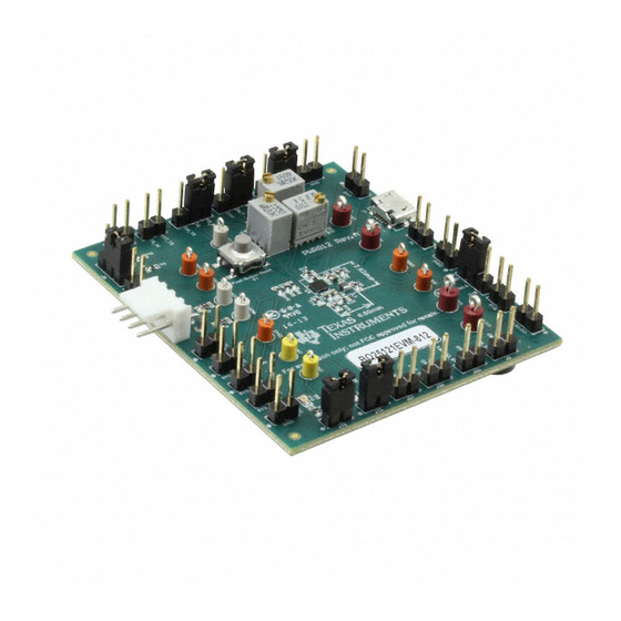
The bq2512x evaluation module (EVM) is a high-performance, easy-to-use development kit for the design
of a compact, flexible, high-efficiency, lower power management solution for single-cell, Li-ion and Li-
polymer batteries used in wearables and low-power portable applications.
This user's guide details both the bq25120EVM and bq25121EVM features, test summary, and test
results. Also included are the EVM schematic, bill of materials, and PCB board layouts.
...................................................................................................................
1
1.1
bq2512x IC Features
1.2
bq2512x EVM Features
1.3
1.4
1.5
1.6
1.7
2
2.1
2.2
2.3
Software GUI (When I
3
3.1
3.2
3.3
3.4
Ship Mode (Optional if I
4
5
5.1
5.2
Board Layouts
1
bq2512xEVM Schematic (bq25120 Represented)
2
BAT Load (PR1010) Schematic
3
Test Setup (PWR731 for bq2512xEVM-731 Shown)
4
EV2400 Interface Box Connection
5
bq2512x Software GUI
6
Select EN_SHIPMODE
.................................................................................................................
7
8
....................................................................................................................
9
SLUUBC8A - August 2015 - Revised May 2016
Submit Documentation Feedback
PCB Configurations
Device
bq25120
bq25121
...............................................................................................
............................................................................................
............................................................................................................
......................................................................................................
...........................................................................................................
.....................................................................................................
................................................................................................................
..................................................................................
2
...............................................................................................................
.............................................................................................
....................................................................................................
........................................................................................
2
................................................................................................................
.......................................................................................
....................................................................................................
.....................................................................................................
...........................................................................................
........................................................................................
......................................................................................................
....................................................................................................
...........................................................................................................
Copyright © 2015-2016, Texas Instruments Incorporated
SLUUBC8A - August 2015 - Revised May 2016
bq2512x Evaluation Module
PCB
PWR731
PWR812
Contents
............................................................................
..........................................................................
.............................................................
...................................................................
List of Figures
......................................................................
...................................................................
User's Guide
bq2512x Evaluation Module
2
2
2
3
4
5
5
6
6
6
7
8
9
9
9
9
9
10
11
11
13
3
6
7
8
8
10
13
13
14
1
Advertisement
Table of Contents

Related Manuals for Texas Instruments bq25120EVM


Summary of Contents for Texas Instruments bq25120EVM
-
Page 1: Table Of Contents
Li-ion and Li- polymer batteries used in wearables and low-power portable applications. This user's guide details both the bq25120EVM and bq25121EVM features, test summary, and test results. Also included are the EVM schematic, bill of materials, and PCB board layouts. - Page 2 Battery charger operates from 3.4 V – 5.5 V V (5.5-V OVP / 20-V tolerant) • C control of key parameters bq2512x Evaluation Module SLUUBC8A – August 2015 – Revised May 2016 Submit Documentation Feedback Copyright © 2015–2016, Texas Instruments Incorporated...
-
Page 3: Introduction
3.6V - 4.65V 1µF 4.99k GND_S- PMID LS/LDO 14.0k 1µF 14.3k PEC03SAAN LS/LDO GND_S- Green Figure 1. bq2512xEVM Schematic (bq25120 Represented) SLUUBC8A – August 2015 – Revised May 2016 bq2512x Evaluation Module Submit Documentation Feedback Copyright © 2015–2016, Texas Instruments Incorporated... -
Page 4: I/O Description
Headers for extra connections to LS/LDO-Force J33 - LS/LDO (Sense line) Headers for LS/LDO-Sense and GND J34 - GND Headers for extra connections to GND bq2512x Evaluation Module SLUUBC8A – August 2015 – Revised May 2016 Submit Documentation Feedback Copyright © 2015–2016, Texas Instruments Incorporated... -
Page 5: Test Points
Table 4. Initial Jumper Position TS = TS_Pot ITERM = GND ISET= GND Installed ILIM = GND Installed VINLS = PMID SLUUBC8A – August 2015 – Revised May 2016 bq2512x Evaluation Module Submit Documentation Feedback Copyright © 2015–2016, Texas Instruments Incorporated... -
Page 6: Recommended Operating Conditions
Figure 2 can simulate a battery when connected to PS#2. Figure 2. BAT Load (PR1010) Schematic bq2512x Evaluation Module SLUUBC8A – August 2015 – Revised May 2016 Submit Documentation Feedback Copyright © 2015–2016, Texas Instruments Incorporated... -
Page 7: Recommended Test Equipment Setup
After the preceding steps are accomplished, the test setup for PWR731 is as shown in Figure 3. The setup is similar for PWR812 with the bq25121. Figure 3. Test Setup (PWR731 for bq2512xEVM-731 Shown) SLUUBC8A – August 2015 – Revised May 2016 bq2512x Evaluation Module Submit Documentation Feedback Copyright © 2015–2016, Texas Instruments Incorporated... -
Page 8: Software Gui
4. Change the parameters in the pull-down menu or check/uncheck the selection box. Figure 4. EV2400 Interface Box Connection Figure 5. bq2512x Software GUI bq2512x Evaluation Module SLUUBC8A – August 2015 – Revised May 2016 Submit Documentation Feedback Copyright © 2015–2016, Texas Instruments Incorporated... -
Page 9: Test Procedure
7. Measure on CM#2 → ICHRG = 5–7 µA 8. Check the box in front of “EN_SHIPMODE” in the software GUI SLUUBC8A – August 2015 – Revised May 2016 bq2512x Evaluation Module Submit Documentation Feedback Copyright © 2015–2016, Texas Instruments Incorporated... -
Page 10: Helpful Hints
IQ: What it is, what it isn’t, and how to use it (SLYT412) bq2512x Evaluation Module SLUUBC8A – August 2015 – Revised May 2016 Submit Documentation Feedback Copyright © 2015–2016, Texas Instruments Incorporated... -
Page 11: Bill Of Materials And Board Layout
RES, 4.99 k, 1%, 0.063 W, 0402 0402 R6, R15, CRCW04020000Z0ED Vishay-Dale RES, 0, 5%, 0.063 W, 0402 0402 R16, R17, R18, R19, SLUUBC8A – August 2015 – Revised May 2016 bq2512x Evaluation Module Submit Documentation Feedback Copyright © 2015–2016, Texas Instruments Incorporated... - Page 12 Wearables and IoT, YFP0025BABD FID1, FID2, Fiducial mark. There is nothing to buy or mount. Fiducial FID3, FID4, FID5, FID6 bq2512x Evaluation Module SLUUBC8A – August 2015 – Revised May 2016 Submit Documentation Feedback Copyright © 2015–2016, Texas Instruments Incorporated...
-
Page 13: Top Overlay
Figure 7 through Figure 16 illustrate the PWR731 EVM PCB board layouts. Figure 7. Top Overlay Figure 8. Top Solder Mask SLUUBC8A – August 2015 – Revised May 2016 bq2512x Evaluation Module Submit Documentation Feedback Copyright © 2015–2016, Texas Instruments Incorporated... -
Page 14: Top Layer
Bill of Materials and Board Layout www.ti.com Figure 9. Top Layer Figure 10. Signal Layer 1 bq2512x Evaluation Module SLUUBC8A – August 2015 – Revised May 2016 Submit Documentation Feedback Copyright © 2015–2016, Texas Instruments Incorporated... -
Page 15: Signal Layer
Bill of Materials and Board Layout www.ti.com Figure 11. Signal Layer 2 Figure 12. Bottom Layer SLUUBC8A – August 2015 – Revised May 2016 bq2512x Evaluation Module Submit Documentation Feedback Copyright © 2015–2016, Texas Instruments Incorporated... -
Page 16: Bottom Solder Mask
Bill of Materials and Board Layout www.ti.com Figure 13. Bottom Solder Mask Figure 14. Bottom Overlay bq2512x Evaluation Module SLUUBC8A – August 2015 – Revised May 2016 Submit Documentation Feedback Copyright © 2015–2016, Texas Instruments Incorporated... -
Page 17: Drill Drawing
Bill of Materials and Board Layout www.ti.com Figure 15. Drill Drawing Figure 16. Board Dimensions SLUUBC8A – August 2015 – Revised May 2016 bq2512x Evaluation Module Submit Documentation Feedback Copyright © 2015–2016, Texas Instruments Incorporated... -
Page 18: Pwr812 Composite Layout
• Changed user's guide globally to accommodate both the bq25120 and bq25121 EVMs..................• Replaced existing BOM with PWR812A BOM. Revision History SLUUBC8A – August 2015 – Revised May 2016 Submit Documentation Feedback Copyright © 2015–2016, Texas Instruments Incorporated... - Page 19 STANDARD TERMS AND CONDITIONS FOR EVALUATION MODULES Delivery: TI delivers TI evaluation boards, kits, or modules, including any accompanying demonstration software, components, or documentation (collectively, an “EVM” or “EVMs”) to the User (“User”) in accordance with the terms and conditions set forth herein. Acceptance of the EVM is expressly subject to the following terms and conditions.
- Page 20 FCC Interference Statement for Class B EVM devices NOTE: This equipment has been tested and found to comply with the limits for a Class B digital device, pursuant to part 15 of the FCC Rules. These limits are designed to provide reasonable protection against harmful interference in a residential installation.
- Page 21 【無線電波を送信する製品の開発キットをお使いになる際の注意事項】 開発キットの中には技術基準適合証明を受けて いないものがあります。 技術適合証明を受けていないもののご使用に際しては、電波法遵守のため、以下のいずれかの 措置を取っていただく必要がありますのでご注意ください。 1. 電波法施行規則第6条第1項第1号に基づく平成18年3月28日総務省告示第173号で定められた電波暗室等の試験設備でご使用 いただく。 2. 実験局の免許を取得後ご使用いただく。 3. 技術基準適合証明を取得後ご使用いただく。 なお、本製品は、上記の「ご使用にあたっての注意」を譲渡先、移転先に通知しない限り、譲渡、移転できないものとします。 上記を遵守頂けない場合は、電波法の罰則が適用される可能性があることをご留意ください。 日本テキサス・イ ンスツルメンツ株式会社 東京都新宿区西新宿6丁目24番1号 西新宿三井ビル 3.3.3 Notice for EVMs for Power Line Communication: Please see http://www.tij.co.jp/lsds/ti_ja/general/eStore/notice_02.page 電力線搬送波通信についての開発キットをお使いになる際の注意事項については、次のところをご覧くださ い。http://www.tij.co.jp/lsds/ti_ja/general/eStore/notice_02.page SPACER EVM Use Restrictions and Warnings: 4.1 EVMS ARE NOT FOR USE IN FUNCTIONAL SAFETY AND/OR SAFETY CRITICAL EVALUATIONS, INCLUDING BUT NOT LIMITED TO EVALUATIONS OF LIFE SUPPORT APPLICATIONS.
- Page 22 Notwithstanding the foregoing, any judgment may be enforced in any United States or foreign court, and TI may seek injunctive relief in any United States or foreign court. Mailing Address: Texas Instruments, Post Office Box 655303, Dallas, Texas 75265 Copyright © 2015, Texas Instruments Incorporated...
- Page 23 IMPORTANT NOTICE Texas Instruments Incorporated and its subsidiaries (TI) reserve the right to make corrections, enhancements, improvements and other changes to its semiconductor products and services per JESD46, latest issue, and to discontinue any product or service per JESD48, latest issue.
Need help?
Do you have a question about the bq25120EVM and is the answer not in the manual?
Questions and answers