Table of Contents
Advertisement
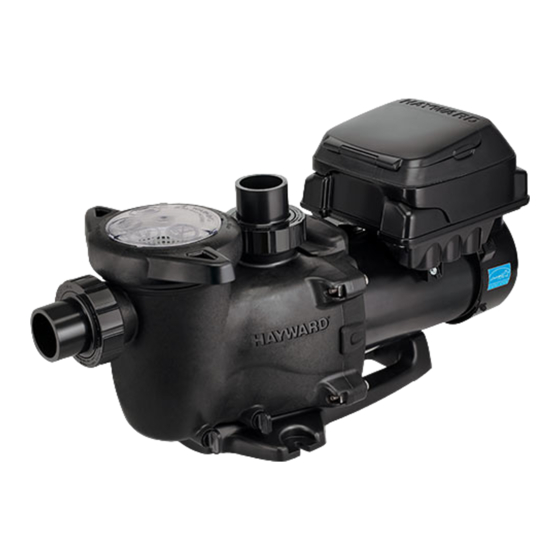
Hayward's MaxFlo VS 500 variable speed pump delivers incredible energy savings via its advanced
hydraulic design combined with a totally enclosed, permanent magnet motor. The MaxFlo VS 500 pump
is easily installed either as a programmable stand-alone pump or with a Hayward or third party
controller and features an easy-to-use digital control interface that can be mounted in four different
positions on the pump or removed and mounted on the wall for total user convenience.
Note: To prevent potential injury and to avoid unnecessary service calls, read this manual carefully and
completely. Unless otherwise stated, instructions in this manual apply to both pump models.
MaxFlo VS
Owner's Manual
Model SP23510VSP
MaxFlo VS 500 Variable Speed Pump
SAVE THIS INSTRUCTION MANUAL
Hayward Pool Products
620 Division St, Elizabeth, NJ 07207
Phone: (908) 355-7995
www.hayward.com
500
™
IS23510VSP Rev-C
Advertisement
Table of Contents

Related Manuals for Hayward SP23510VSP


Summary of Contents for Hayward SP23510VSP
- Page 1 The MaxFlo VS 500 pump is easily installed either as a programmable stand-alone pump or with a Hayward or third party controller and features an easy-to-use digital control interface that can be mounted in four different positions on the pump or removed and mounted on the wall for total user convenience.
-
Page 2: Table Of Contents
Storing Pump For Winterization Shaft Seal Change Instructions ........................26 9.1. Removing the Motor Assembly 9.2. Removing the Impeller USE ONLY HAYWARD GENUINE REPLACEMENT PARTS Page 2 of 32 MaxFlo VS 500 Variable Speed Pump IS23510VSP Rev-C... - Page 3 11.1. General Problems 11.2. Check System Messages Product Registration ............................. 30 Warranty ............................... 31 USE ONLY HAYWARD GENUINE REPLACEMENT PARTS Page 3 of 32 MaxFlo VS 500 Variable Speed Pump IS23510VSP Rev-C...
-
Page 4: Important Safety Instructions
– All electrical wiring MUST be in conformance with all applicable local codes, regulations, and the National Electric Code (NEC). USE OF NON-HAYWARD REPLACEMENT PARTS VOIDS WARRANTY. ATTENTION INSTALLER - THIS MANUAL CONTAINS IMPORTANT INFORMATION ABOUT THE INSTALLATION, OPERATION, AND SAFE USE OF THIS VARIABLE SPEED PUMP THAT MUST BE FURNISHED TO THE END USER OF THIS PRODUCT. - Page 5 Mechanical Entrapment - There is potential for jewelry, swimsuits, hair decorations, fingers, toes, or knuckles to be caught in an opening of a suction outlet cover resulting in mechanical entrapment. USE ONLY HAYWARD GENUINE REPLACEMENT PARTS Page 5 of 32...
- Page 6 WARNING – Failure to install according to defined instructions may result in severe personal injury or death. SAVE THESE INSTRUCTIONS USE ONLY HAYWARD GENUINE REPLACEMENT PARTS Page 6 of 32 MaxFlo VS 500 Variable Speed Pump IS23510VSP Rev-C...
-
Page 7: General Information
2. General Information 2.1. Introduction This manual contains information for the proper installation and operation of the Hayward MaxFlo VS 500 Variable Speed Pump. The instructions in this manual MUST be followed precisely. 2.2. Primary Features Totally enclosed, permanent magnet motor ... -
Page 8: Installation And Wiring
Allow for valves in suction and discharge piping. Be protected from excess moisture and flooding. Allow adequate access for servicing pump and piping. USE ONLY HAYWARD GENUINE REPLACEMENT PARTS Page 8 of 32 MaxFlo VS 500 Variable Speed Pump IS23510VSP Rev-C... -
Page 9: Pipe Sizing Chart
Use copper conductors only. USE ONLY HAYWARD GENUINE REPLACEMENT PARTS Page 9 of 32 MaxFlo VS 500 Variable Speed Pump... -
Page 10: Electrical Specs
MaxFlo VS 500 can operate by itself in Stand-Alone Mode using its built-in programmable timers. 2. MaxFlo VS 500 can also be controlled from third party controls (i.e. another manufacturer’s control) and Hayward controls that are not software compatible using relay contacts. See section 5.3 for more information regarding connecting MaxFlo VS 500 and third party/non-software compatible Hayward controls. -
Page 11: Digital Control Interface Orientation
(Figure 4.11-1) Figure 4.11-1 USE ONLY HAYWARD GENUINE REPLACEMENT PARTS Page 11 of 32 MaxFlo VS 500 Variable Speed Pump... -
Page 12: Interface Wall Mounting
11. Apply power to the system and resume normal operation. The following diagrams illustrate the interface wall mounting procedure. Figure 4.12-1: Removing the Digital Control Interface for Wall Mounting USE ONLY HAYWARD GENUINE REPLACEMENT PARTS Page 12 of 32 MaxFlo VS 500 Variable Speed Pump... - Page 13 Figure 4.12-2: Removing the Interface Mounting Plate to access the Drive wiring compartment Figure 4.12-3: Adding the Blank Cover USE ONLY HAYWARD GENUINE REPLACEMENT PARTS Page 13 of 32 MaxFlo VS 500 Variable Speed Pump IS23510VSP Rev-C...
-
Page 14: Installation Procedure
Note: The interface mounting plate/wiring compartment cover must be installed properly to provide environmental protection for the wiring compartment. 9. Apply power to the system, and proceed to “Configuration Menu”, section 6.6. USE ONLY HAYWARD GENUINE REPLACEMENT PARTS Page 14 of 32 MaxFlo VS 500 Variable Speed Pump... -
Page 15: Wiring Diagrams
Terminal block must be installed with screws facing up to ensure proper connection. SW200 DIP switch #1 and #2 must be “ON”. USE ONLY HAYWARD GENUINE REPLACEMENT PARTS Page 15 of 32... -
Page 16: External Relay Speed Control Wiring (For Remote Selection Of Pump Speed)
SW200 DIP switch #1 and #2 must be “ON”. The MaxFlo VS 500 can be controlled from third party pool controls as well as Hayward controls that are not software compatible using relay contacts to select the speeds set in the Timer Menu (see section 6.7). -
Page 17: Remote Stop Switch Wiring (Optional)
Have a professional perform this test. 2. Ensure all Hayward pump and system components are removed from system prior to performing test. WARNING – If circulation equipment must remain in the plumbing system during water pressure test, do not apply more than 10 psi pressure to the system. -
Page 18: Starting/Priming The Pump
If pump does NOT prime within 10 minutes, stop motor and determine cause. Be sure all suction and discharge valves are open when pump is running. See Troubleshooting Guide. USE ONLY HAYWARD GENUINE REPLACEMENT PARTS Page 18 of 32 MaxFlo VS 500 Variable Speed Pump... -
Page 19: User Interface Summary
5. Quick Clean: QUICK CLEAN is a mode intended for use when the pool will be cleaned with a suction side vacuum. USE ONLY HAYWARD GENUINE REPLACEMENT PARTS Page 19 of 32 MaxFlo VS 500 Variable Speed Pump IS23510VSP Rev-C... -
Page 20: Menu Outline
(see section 6.7 for more details). At this point, pressing the MENU button will select the Configuration Menu. USE ONLY HAYWARD GENUINE REPLACEMENT PARTS Page 20 of 32 MaxFlo VS 500 Variable Speed Pump... -
Page 21: Configuration Menu
MAX allowed speed setting for 8 hours. Low temperature operation is active when the pump is being remotely controlled. Low temperature operation is NOT intended to protect the USE ONLY HAYWARD GENUINE REPLACEMENT PARTS Page 21 of 32... -
Page 22: Timer Menu
Control Mode is set to Relay Control, the speed for Timer 1 may be set to 0 rpm to allow the pump to be stopped without having to remove power. USE ONLY HAYWARD GENUINE REPLACEMENT PARTS Page 22 of 32... -
Page 23: Preset Speed Setup Menu
DC Bus Voltage Displays status of internal DC bus voltage. Within Range Motor Current Real-time display of motor input current. 1.1A (8.5A Max) USE ONLY HAYWARD GENUINE REPLACEMENT PARTS Page 23 of 32 MaxFlo VS 500 Variable Speed Pump IS23510VSP Rev-C... -
Page 24: Stop/Resume
60 min, and it may be cancelled early by pressing the Stop/Resume button, at which time the pump would return to normal operation. USE ONLY HAYWARD GENUINE REPLACEMENT PARTS Page 24 of 32 MaxFlo VS 500 Variable Speed Pump... -
Page 25: Remote Stop
Keep motor clean. Insure motor air vents are free from obstruction to avoid damage. Do NOT use water to hose off motor. Occasionally, shaft seals must be replaced, due to wear or damage. Replace with genuine Hayward seal assembly kit. See “Shaft Seal Change Instructions” in this manual. 8. Storage / Winterization WARNING –... -
Page 26: Shaft Seal Change Instructions
Disconnect all electrical power service to pump before beginning shaft seal replacement. Only qualified personnel should attempt rotary seal replacement. Contact your local authorized Hayward Dealer or service center if you have any questions. Refer to Figure 10.1-1 for pump component locations. -
Page 27: Replacing The Motor Assembly
10. Replacement Parts 10.1. Parts Diagram Figure 10.1-1 USE ONLY HAYWARD GENUINE REPLACEMENT PARTS Page 27 of 32 MaxFlo VS 500 Variable Speed Pump IS23510VSP Rev-C... -
Page 28: Parts Listing
Check for low voltage or power drop at the motor (frequently caused by undersized wiring). Contact a qualified professional to verify the electrical connections. USE ONLY HAYWARD GENUINE REPLACEMENT PARTS Page 28 of 32 MaxFlo VS 500 Variable Speed Pump... - Page 29 2. Check for and correct any improper or loose wiring connections. 3. Install noise filter (from home automation/power line communication equipment vendor) to prevent equipment interference. USE ONLY HAYWARD GENUINE REPLACEMENT PARTS Page 29 of 32 MaxFlo VS 500 Variable Speed Pump...
-
Page 30: Check System Messages
If the troubleshooting steps listed above do not help to resolve the error condition, then the problem may be internal to the motor/drive. Contact Hayward Technical Service at (908) 355-7995 for additional assistance. -
Page 31: Warranty
13. Warranty USE ONLY HAYWARD GENUINE REPLACEMENT PARTS Page 31 of 32 MaxFlo VS 500 Variable Speed Pump IS23510VSP Rev-C... - Page 32 Other_____________________________ Model Number_____________________________________________________ Pool Capacity_______________(U.S. Gallons) New Installation Replacement Please include me on all e-mail communications regarding Hayward Equipment or promotions. Mail to: Hayward Pool Products, 620 Division Street, Elizabeth, NJ 07207 Installation for: Attn: Warranty Dept In Ground OR REGISTER YOUR WARRANTY ON-LINE AT WWW.HAYWARD.COM and MaxFlo VS 500 are registered trademarks of Hayward Industries, Inc.
Need help?
Do you have a question about the SP23510VSP and is the answer not in the manual?
Questions and answers