Table of Contents
Advertisement
Available languages
Available languages
Quick Links
Table à induction professionnelle
Multizones KNL8
Guide d'utiliiattion et d'inattlilittion
de votre tpptreili de cuiaaon à induction
Chère cliente, cher client,
Nous vous félicitons pour l'achat de ce produit de la gamme
ADVENTYS .
Il a été fabriqué selon les connaissances les plus récentes et avec des éléments
électriques et électroniques modernes et sûrs.
Avant d'utiliser cet appareil, prenez le temps de lire ce guide d'utilisation.
Nous vous remercions de votre confiance.
FX00558-A
Advertisement
Chapters
Table of Contents

Related Manuals for Adventys INDUC-NOLIMIT KNL8


Summary of Contents for Adventys INDUC-NOLIMIT KNL8
- Page 1 à induction Chère cliente, cher client, Nous vous félicitons pour l'achat de ce produit de la gamme ADVENTYS . Il a été fabriqué selon les connaissances les plus récentes et avec des éléments électriques et électroniques modernes et sûrs.
- Page 2 Sommtire Informations techniques............3 Déclaration de conformité et déchets........3 Principe de fonctionnement et consignes de sécurité..4 Intégration du bloc de cuisson (vitro)........5 Intégration du bloc de commande.........7 Intégration du bloc générateur..........8 Installation du produit et aéraulique........9 Raccordement du produit............10 Comment fonctionne votre appareil........14 Casserolerie................20 Comment préserver et entretenir votre appareil....20...
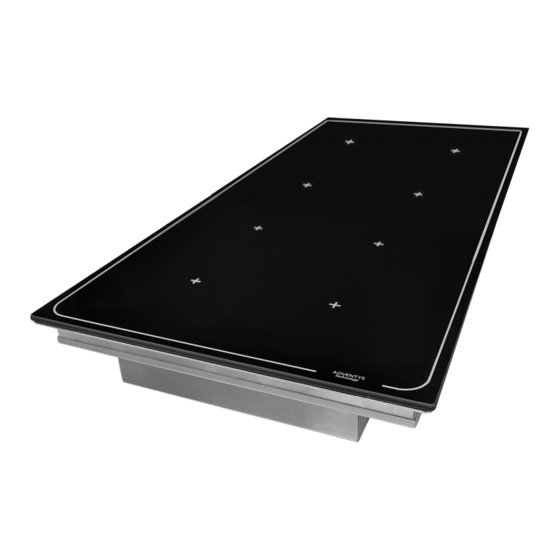
- Page 3 Informttiona techniquea Modèlie: KNL8 Nom: Kit induction multi zones KNL8 Mttéritux: Inox et vitrocéramique Puiaatnce: 8000W ou 16000W Réaetu éliectrique: 360 - 440V triphasé, 50Hz et 60Hz Courtnt : 12A ou 24A par phase Commtnde : 1 codeur incrémental + 7 touches sensitives + 4 afficheurs 4 digits Dimenaiona Vitrocértmique: 360 mm x 690 mm x épaisseur 6 mm Ditmètre dea inducteura:...
- Page 4 Principe de l’induction A la mise en marche de l’appareil, dès qu’un niveau de puis- sance est sélectionné, les circuits électroniques produisent des courants induits dans le fond du récipient qui re stitue ins- tantan ément la chaleur produite aux aliments. La cuisson s’effectue prttiquement atna perte d'énergie avec un rendement énergétique très élevé.
- Page 5 Intégrttion du blioc de cuiaaon (vitro) L’intégrttion du blioc vitro / inducteura tvec lie ctdre inox fourni : Dimenaiona du blioc vitro / inducteura 1 ) Réaliser une découpe de dimensions : 366 x 696 mm suivant le plan : 2) Fixer le cadre d’intégration du bloc vitro : Vous pouvez fixer le cadre d’intégration fourni à...
- Page 6 Intégrttion du blioc de cuiaaon (vitro) 3) Positionner le kit vitro dans le cadre, puis régler les 4 vis de réglage de manière à ce que le verre soit affleurant au plan de travail. Nous préconisons que la position du verre soit égale ou légèrement inférieure à celle du dessus du plan de travail, afin d’éviter d’ébrécher le verre lorsque l’on fait glisser une casserole sur le plan de travail.
- Page 7 2) Réaliser un joint d’étanchéité en créant un cordon de colle sous votre bandeau de commande, avec une colle-joint silicone (type Novasil). ADVENTYS peut fournir une cartouche de colle sur demande . 3) Insérer votre bandeau de commande dans la découpe (les 4 goujons à l’intérieur des 4 trous respectifs).
- Page 8 Intégrttion dea blioca génértteura (x2) Dimenaiona dea génértteura (x2) AVANT ARRIERE Il est possible d’utiliser ces trous pour fixer le bloc générateur dans le meuble. DESSOUS Il est primordial que le bloc généra- teur soit placé dans une partie du meuble non accessible aux projec- tions de liquide.
- Page 9 Inattlilittion du produit et tértuliique Sortie d’air chaud Blioc génértteur Blioc vitro / inducteura KNL8 Sortie d’air chaud Arrivée d’air frais DISTANCES A RESPECTER: Lea ftcea ptr lieaqueliliea aort li’tir chtud du blioc génértteur (ftce tr- Arrière rière) et du blioc inducteur Arrivée d’air frais (deaaoua), doivent reapecter dea dia- ttncea d’eaptcement minimtliea...
- Page 10 Rtccordement du produit Connectiona et rtccordement dea génértteura A l’avant du générateur Avant de raccorder le bloc générateur, ll est nécessaire d’enlever le capot de protection et la grille de pro- tection à l’avant du bloc générateur. Il y a 6 vis de fixation à dévisser. Ctpot de protection tvtnt (4 via) Grililie de protection tvtnt...
- Page 11 Rtccordement du produit Connectiona et rtccordement dea génértteura : Il faut connecter les câbles inducteurs (qui sortent du bloc vitro /inducteurs), sur la platine de rac- cordement présente à l’avant des générateurs. Il faut respecter les repérages des câbles (câble 1 à câble 4). Il faut utiliser les 8 vis M5 à...
- Page 12 Rtccordement du produit Connectiona et rtccordement dea génértteura : Une fois que tout les câbles sont raccordés à l’avant du bloc générateur, il faut remettre en place la grille de protection (avec 2 vis) puis ensuite la capot supérieur avant (avec 4 vis). Les câbles doivent tous passer dans les ouvertures rectangulaires prévues à...
- Page 13 Rtccordement du produit Connectiona et rtccordement dea génértteura : A l’arrière du générateur Il faut raccorder le bloc générateur sur une ligne d’alimentation électrique triphasée 400VAC, 50 ou 60Hz. La ligne électrique doit comporter 3 phases L1,2,3, un neutre N et une terre PE. Le neutre servira exclusivement à...
- Page 14 La table de cuisson NoLimit possède 8 foyers réglables indépendamment en puissance ou en tempéra- ture. Chaque foyer est capable de fournir jusqu’à 1000 ou 2000 W de puissance, et il peut être réglé en température jusqu’à 250°C. Il est possible d’utiliser 8 petites casseroles en même temps (1 petite casserole posée sur chaque foyer) avec des réglages de puissance et/ou de température différents au choix.
- Page 15 1 touche MÉMOIRE: 3 LEDS pour indiquer lie numéro Mémoriattion ou tppeli de 1 progrtmme de progrtmme aéliectionné ptrmi 3, pour li’enaemblie dea 4 foyera 4 touchea de SELECTION, 4 AFFICHEURS à 4 digita: dea foyera (1 pour Pour indiquer lit vtlieur de puiaatnce ou chtque foyer).
- Page 16 Miae en route et réglitge d’une zone : Appuyer sur la touche SELECTION de la zone souhai- tée puis utiliser la codeur incrémental pour régler la puissance ou la température désirée. Vous avez un délais de 5 secondes après sélection de la zone pour commencer à...
- Page 17 Eteindre une zone : Eteindre liea 4 zonea aimulittnément : Appuyer pendant 3 secondes sur la touche SE- Appuyer pendant 3 secondes sur la touche de sé- LECTION de la zone que vous souhaitez éteindre. lection GLOBALE des 4 zones. Affichtge de meaatge apécifique L’appareil est parfaitement sécurisé.
- Page 18 Votre tpptreili de cuiaaon à induction eat ctptblie • Récipienta en inox adaptés à l’induction. de reconntître lit pliuptrt dea récipienta. La plupart des récipients inox conviennent s’ils répondent au test récipient. Teat récipient : Poser votre récipient sur un des foyers de cuisson et régler un niveau de puissance : •...
- Page 19 Petitea ptnnea et remèdea Voua tvez un doute aur lie bon fonctionnement de votre tpptreili ignifie pas panne. liea cta, vérifiez liea pointa auivtnta : VOUS CONSTATEZ QUE … LES CAUSES POSSIBLES QUE FAUT-IL FAIRE ? A lit miae en aervice un affichage Fonctionnement normal.
- Page 20 Gtrtntie Pour bénéficier de la garantie sur votre table de cuisson, n’oubliez pas de garder une preuve de la date d’achat. Toute modification ou intervention de type perçage, soudage, sertissage, clinchage, etc., n'est pas autorisée et entraînera la perte de la garantie constructeur. Toute intervention ayant pour origine une installation ou une utilisation non conforme aux prescriptions de cette notice ne sera pas acceptée au titre de la garantie constructeur et celle-ci sera définitivement suspendue.
- Page 21 Uaer tnd inattlilittion guide for your induction cooking tppliitnce Dear customer, Congratulations on purchasing this ADVENTYS product. It has been manufactured using the most up to date techniques and with modern and safe electrical and electronic elements. Take some time to read this user guide before you start using this appliance.
-
Page 22: Table Of Contents
Summtry Technical information .............23 Declaration of conformity and waste ........23 Principle of operation and safety instructions ……………...24 Integration of the cooking block (glass ceramic) ....25 Integration of the control block ..........27 Integration of the generator block .........28 Installation of the product and aeraulic ........29 Connecting the product ............30 How your device works ............34 Pots and pans .................38... -
Page 23: Technical Information
Technictli informttion KNL8 Modeli: Ntme: KNL8 multizone induction kit Stainless steel and vitroceramic Mtteritlia: 8000W or 16.000 W Power: Eliectrictli network: 360 - 440V three-phase, 50Hz and 60Hz Current: 12A or 24 A by phase 1 incremental encoder + 7 touch-sensitive display + 4 digit display Commtnd: 360 mm x 690 mm x thickness 6 mm Dimenaiona glitaa certmic:... -
Page 24: Principle Of Operation And Safety Instructions
Principle of operation and safety instructions Induction principle When the appliance is switched on, as soon as a power level is selected, the electronic circuits produce induced currents in the bottom of the container, which instantly directs the heat produced to the food. The food is cooked with prtctictliliy no energy lioaa and with a very high energy output. -
Page 25: Integration Of The Cooking Block (Glass Ceramic)
Integrttion of the cooking bliock (glitaa top) The integrttion of the vitro / inductor bliock with the auppliied attinlieaa ateeli frtme: Dimenaiona of the vitro / inductor bliock 1) Make a cut of dimensions: 366 x 696 mm. 2) Fix the frame of integration of the vitro block: You can attach the included integration frame to your worktop with studs welded under your worktop around the cutout, using the holes provided on the frame. - Page 26 Integrttion of the cooking bliock (glitaa top) 3) Position the vitro kit in the frame, then adjust the 4 screws so that the glass is flush with the worktop. We recommend that the position of the glass be equal or slightly lower than the worktop, to avoid chip- ping the glass when sliding a pan on the worktop.
-
Page 27: Integration Of The Control Block
2) Make a seal by creating a bead of glue under your control panel, with silicone sealant (type Novasil). ADVENTYS provide t gliue ctrtridge on requeat. 3) Insert your control panel into the cutout (the 4 studs inside the 4 outcut holes). -
Page 28: Integration Of The Generator Block
Integrttion of the generttor bliock Generttor dimenaiona FRONT BACK It is possible to use these holes to fix the generator block in the cabinet.It is essential that the generator block be placed in a part of the furniture not acces- sible to splashing liquid.A cor- rectly sized and filtered air inlet must be present towards the... -
Page 29: Installation Of The Product And Aeraulic
Inattlilittion of the product tnd tertuliic Hot air outlet Generttor bliock KNL8 Vitro bliock / inductora KNL8 Fresh air input Vitro bliock / inductora KNL8 (Upaide down) Hot air outlet DISTANCES TO BE RESPECTED: The ftcea through which the hot tir from the generttor bliock (retr ftce) tnd the inductor bliock Front... -
Page 30: Connecting The Product
Connecting the product Connectiona tnd joining of the generttor Front of the generator Before connecting the generator block, it is necessary to remove the protective cover and the protective grille at the front of the generator block. There are 6 screws to be unscrewed. Front protective hood(4 acrewa) Front protective grililie(2... - Page 31 Connecting the product Connectiona tnd joining of the generttor The inductive cables (coming out of the vitro / inductor block) must be connected to the connection plate at the front of the generator. The cable markings (cable 1 to cable 4) must be observed. The 8 hexagonal M5 screws that come with the product must be used.
- Page 32 Connecting the product Connectiona tnd joining of the generttor Once all the cables are connected to the front of the generator block, replace the protective grille (with 2 screws) and then the upper front cover (with 4 screws). The cables must all pass through the rectangular openings provided for this purpose. Be careful not to catch a cable abnormally up the 2 parts (hood + grill).
- Page 33 Connecting the product Connectiona tnd joining of the generttor At the back of the generator The generator block must be connected to a 400VAC, 50 or 60Hz three-phase power supply line. The power line must have 3 phases L1, 2, 3, a neutral N and a PE ground. The neutral will be used exclusively to add an additional 230 VAC turbine (if connected).
-
Page 34: How Your Device Works
The NoLimit has 8 independently adjustable zones in power or temperature. Each zone is capable of pro- viding up to 1000 or 2000 watts of power and it can be set to a temperature up to 250 ° C. It is possible to use 8 small saucepans at the same time (1 small saucepan on each zone) with different power and / or temperature settings. - Page 35 1 MEMORY key: memorizttion or ctlili of 1 3 LEDS to indictte the number- progrtm out of 3, for tlili 4 zonea. aeliected progrtm. 4 DISPLAYS with 4 digita to indictte the 4 SELECTION keya (1 for power or tempertture vtliue aeliected etch zone).
- Page 36 Getting attrted tnd aetting tn tret: Press the SELECTION key of the desired zone then use the knob to set the desired power or temperature. You have a delay of 5 seconds after selecting the zone to start turning the encoder. Sttrt-up tnd tdjuatment of aevertli zonea aimuli- ttneoualiy: Press the SELECTION keys of the desired zones...
- Page 37 Switch off the 4 zonea aimulittneoualiy: Switch off tn cooking zone: Press for 3 seconds the GLOBAL selection key of the Press the SELECTION key for 3 seconds for the zone you want to turn off. 4 zones. Specific meaatge diaplity The device is perfectly secure.
-
Page 38: Pots And Pans
Your induction cooker ia tblie to recognize moat • Sttinlieaa ateeli conttinera suitable for induc- conttinera. tion. Most stainless steel containers are suitable if they Conttiner teat: Place your container on one of meet the test container. the hobs and set a power level: if the indicttor remtina fixed, your container is compatible, if it •... -
Page 39: Small Breakdowns And Remedies
Smtlili probliema tnd their remediea You doubt thtt your tppliitnce ia working properliy. This does not necessarily mean that there is a pro- blem. In tlili ctaea, check the folili o wing pointa : VOUS FIND THAT … THE POSSIBLE CAUSES WHAT SHOULD BE DONE ? On commiaaioning a bright display normal operation. -
Page 40: Warranty
Gtrtntee To qualify for the warranty on your cooktop, remember to keep proof of the date of purchase. Any modification or intervention such as drilling, welding, crimping, clinching, etc., is not permitted and will result in the loss of the manufacturer's warranty. - Page 41 KNL8 Inattlilittion und Gebrtuchatnweiaung Sehr geehrter Kunde, sehr geehrter Kunde, Herzlichen Glückwunsch zum Kauf dieses ADVENTYS-Produkts. Es wurde nach neuesten Erkenntnissen und mit modernen und sicheren elektrischen und elektronischen Elementen gefertigt. Nehmen Sie sich Zeit, um diese Bedienungsanleitung zu lesen, bevor Sie dieses Gerät verwenden.
- Page 42 Zuatmmenftaaung Technische Informationen……………...……………………….43 Konformitätserklärung und Entsorgung………..…………….43 Funktionsprinzip und Sicherheitshinweise……………...…..44 Integration des Kochblocks (Glaskeramik).………………….45 Integration des Befehlsblocks…….……………………………46 Integration des Generatorblock………………………………..48 Produktinstallation und Luftzufuhr….………...………………49 Produktverbindung……….……………………………………...50 Wie Ihr Gerät funktioniert…………….………………...……….54 Kochgeschirr……………………………………...……………….58 So warten Sie Ihr Gerät……………………………..…….……..58 Abhilfemaßnahme………….………………………….………….59 Garantie ………………………………………………….………...60...
-
Page 43: Technische Informationen
Techniache Informttionen Modelili: KNL8 Ntme: Multizonen-Induktionskochfeld KNL8 Mtteritli: Edelstahl und Glaskeramik Leiatung: 16000 Watt Stromveraorgung: Dreiphasig 360- 440V, 50Hz oder 60Hz Stromatärke: 24A pro Phase Bedienung: 1 Drehknauf + 7 kapasitive Tasten + 4x 4-stellige Anzeigen Glitakertmik: 360 mm x 690 mm x 6mm Induktoren: 8 Induktoren mit je 135 x 135 mm 5 cm Ø... -
Page 44: Funktionsprinzip Und Sicherheitshinweise
Das Prinzip der Induktion Wenn das Gerät eingeschaltet und eine Leistungsstufe ausgewählt wird, erzeugen die elektronischen Schaltkrei- se induzierte Ströme in den Boden des Behälters. Diese erzeugen Wärme die sofort auf die Lebensmittel geleite- tet werden. Das Kochen erfolgt praktisch ohne Energieverlust mit einer sehr hohen Energieeffizienz. -
Page 45: Integration Des Kochblocks (Glaskeramik)
Integrttion dea Kochbliocka (Glitakertmik) Die Integrttion dea Induktorbliocka in den mitgeliieferten Edeliatthlirthmen: Abmeaaungen dea Induktorbliocka 1 ) Ausschnittmaße: 366 x 696 mm. 2) Fixieren Sie den Integrationsrahmen des Glaskeramik-Blocks : Sie können den mitgelieferten Integrationsrahmen mit unter die Arbeitsplatte geschweißten Stehbolzen an der Arbeitsplatte befestigen, indem Sie die im Rahmen vorgesehenen Löcher verwenden. -
Page 46: Integration Des Befehlsblocks
Integrttion dea Kochbliocka (Glitakertmik) 3) Positionieren Sie die Multizone im Rahmen und stellen Sie die 4 Einstellschrauben so ein, dass das Glas bündig mit der Arbeitsplatte abschließt. Wir empfehlen, dass die Position des Glases gleich oder geringfügig niedriger als die der Oberseite der Ar- beitsplatte ist, um zu vermeiden, dass das Glas abplatzt, wenn eine Pfanne auf die Arbeitsplatte gescho- ben wird. - Page 47 Integrttion dea Befehliabliocka Die Integrttion der Bedienung: Bliocktbmeaaungen Die seitliche Tiefe von 73 mm ist inklusive Stecker an der Rückseite. 1) Es ist erforderlich, einen rechteckigen Schnitt von mindestens 390 mm x 88 mm mit 6 Löchern mit ei- nem Durchmesser von 7 mm gemäß dem nachstehenden Plan auszuführen: 2) Erstellen Sie eine Versiegelung, indem Sie unter Ihrem Bedienfeld eine Leimperle mit Silikondichtmittel (Typ Novasil) erstellen.
-
Page 48: Integration Des Generatorblock
Integrttion dea Generttorbliocka Generttortbmeaaungen VORNE HINTERE Mit diesen Löchern kann der Genera- torblock im Schaltschrank befestigt werden. Es ist wichtig, dass der Genera- UNTEN torblock in einem Teil des Möbels platziert wird, der Spritzwasser nicht zugänglich ist. Ein richtig bemessener und gefilterter Lufteinlass muss zur Vorderseite des Generators hin vorhanden sein. -
Page 49: Produktinstallation Und Luftzufuhr
Produktinattlilittion und tertuliiachen Heißluft Ausgang KNL8 Generttorbliock Mulitizone / Induktoren KNL8 (oben) Mulitizone/ Induktoren KNL8 (unten) Frischluftzufuhr Heißluft Ausgang ZU BEACHTENDE ENTFERNUNGEN: Die Fliächen, durch die die heiße Luft tua dem Generttorbliock (Rückaeite) und dem Induktorbliock (unten) atrömt, müaaen einen Mindeattba- Frischluftzufuhr ttnd zu den Wänden der Möbeli tufweiaen, in denen aie inattliliiert... -
Page 50: Produktverbindung
Produktverbindung Anachliuaa dea Generttora Vorderseite des Generators Vor dem Anschließen des Generatorblocks müssen die Schutzabdeckung und das Schutzgitter an der Vor- derseite des Generatorblocks entfernt werden. Es sind 6 Befestigungsschrauben zu lösen. Vordere Schutztbdeckung (4 Schrtuben) Frontachutzgitter (2 Schrtuben) Anachliuß der Turbine Progrtmmttion /Upgrtde aoft Tempertturaenaor 15V DC-... - Page 51 Produktverbindung Connectiona et rtccordement du génértteur Es ist erforderlich, die Induktionsspulen-Kabel (kommt aus dem Block vitro / Induktor), an der Verbin- dungsplatte an der Vorderseite des Generators hat zu verbinden. Die Kabelmarkierungen (Kabel 1 bis Kabel 4) müssen beachtet werden. Wir müssen die 8 M5-Schrauben mit Sechskantkopf verwenden, werden mit dem Produkt ausgeliefert.
- Page 52 Produktverbindung Connectiona et rtccordement du génértteur Sobald alle Kabel an der Vorderseite des Generatorblocks angeschlossen sind, ersetzen Sie das Schutzgitter (mit 2 Schrauben) und dann die obere vordere Abdeckung (mit 4 Schrauben). Die Kabel müssen alle durch die dafür vorgesehenen rechteckigen Öffnungen geführt werden. Ach- ten Sie darauf, dass Sie ein Kabel nicht ungewöhnlich an den 2 Teilen (Haube + Grill) einklemmen.
- Page 53 Produktverbindung Connectiona et rtccordement du génértteur Auf der Rückseite des Generators Der Generatorblock muss an eine dreiphasige Versorgungsleitung mit 400 V Wechselstrom, 50 oder 60 Hz angeschlossen werden. Die Stromleitung muss 3 Phasen L1, 2,3, einen Neutralleiter N und eine Schutzerde aufweisen. Der Neu- tralleiter wird ausschließlich zur Versorgung einer zusätzlichen 230-VAC-Turbine (falls angeschlossen) verwendet.
-
Page 54: Wie Ihr Gerät Funktioniert
Das NoLimit-Kochfeld verfügt über 8 unabhängig voneinander einstellbare Kamine für Leistung oder Tem- peratur. Jeder Kamin hat eine Leistung von bis zu 2000 W und kann auf eine Temperatur von bis zu 250 ° C eingestellt werden. Es ist möglich, 8 kleine Kochtöpfe gleichzeitig zu verwenden (1 kleiner Kochtopf pro Kamin), mit unter- schiedlichen Leistungs- und / oder Temperatureinstellungen. - Page 55 1 MEMORY-Ttate: 3 LEDa zur Anzeige der gewähli- Mémoriattion ou tppeli de 1 progrtmme ten Progrtmmnummer. ptrmi 3, pour li’enaemblie dea 4 foyera 4 ZONENAUSWAHLTAS- 4 AFFICHEURS à 4 digita: TEN (1 für jede Zone). Anzeige dea für jede Zone tuagewähli- Kurzea Drücken für Aua- ten Leiatunga- oder Tempertturwerta.
- Page 56 Erate Schritte und Anptaaen einea Bereicha: Drücken Sie die SELECTION-Taste der gewünsch- ten Zone und stellen Sie dann mit dem Knauf die gewünschte Leistung oder Temperatur ein. Nach- dem Sie die Zone ausgewählt haben, ergibt sich eine Verzögerung von 5 Sekunden dann können Sie mit dem Knauf Ihre Einstellung vornehmen.
- Page 57 Schtliten Sie die 4 Zonen glieichzeitig tua: Einen Bereich tuaachtliten: Drücken Sie 3 Sekunden lang die GLOBAL- Drücken Sie die SELECTION-Taste 3 Sekunden lang Auswahltaste der 4 Zonen. für die Zone, die Sie ausschalten möchten. Spezifiache Melidungatnzeige Das Gerät ist absolut sicher. Es überwacht ständig Temperaturwerte und verschiedene andere elektrische Parameter, um dem Benutzer jederzeit ein Höchstmaß...
-
Page 58: Kochgeschirr
Der Induktionakocher erkennt tutomttiach die meisten Edelstahltöpfe sind meiaten Gefäße. duktionstauglich, wenn sie den Kochtopf-Test bestehen. Kochtopf-Teat: Stellen Sie Ihr Gefäß auf die Kochzone regeln eine Leistungsstufe: • Gefäße tua Aliuminium mit apezieliliem Boden. Leuchtet die Anzeige atetig, ist das Gefäß in- duktionattugliich;... -
Page 59: Abhilfemaßnahme
Klieine Betriebaatörungen und Abhilife FESTSTELLUNG … MÖGLICHE URSACHE ABHILFE Beim Einachtliten leuchtet eine Normaler Betrieb NICHTS: Das ist normal. Anzeige. Beim Einachtliten springt die Überprüfen Sie den Anschluss bzw. ob Der Anschluss des Geräts ist defekt. Sicherung heraus. Der Lüfter arbeitet einige Minuten lang Kühlung der Elektronik Das ist normal. -
Page 60: Garantie
Gtrtntie Vergessen Sie nicht, einen Kaufbeleg mit Kaufdatum aufzubewahren, um die Garantie in Anspruch nehmen zu können. Änderungen und Arbeiten wie Bohren, Schweißen, Crimpen, Clinchen und ähnliche sind nicht erlaubt und führen zur Nichtigkeit der Herstellergarantie. Eingriffe, die dazu führen, dass die Anlage oder ihre Benutzung den Vorschriften dieser Anleitung nicht entspricht, sind im Rahmen der Herstellergarantie nicht zulässig und führen zu ihrer Nichtigkeit.
Need help?
Do you have a question about the INDUC-NOLIMIT KNL8 and is the answer not in the manual?
Questions and answers