Table of Contents
Advertisement
Quick Links
TURBO HD TVI
Bullet & Turret Camera
User Manual
User Manual
Thank you for purchasing our product. If there are any
questions, or requests, do not hesitate to contact the
dealer.
This manual applies to the model listed below.
Type
Model
Type I
DS-2CE16D0T-IT1E/3E/5E
Type II
DS-2CE16D0T-IRE/IRPE
Type III
DS-2CE56D0T-IT1E/3E
Type IV
DS-2CE56D0T-ITME
This manual may contain several technically incorrect
places or printing errors, and the content is subject to
change without notice. The updates will be added to
the new version of this manual. We will readily improve
or update the products or procedures described in the
manual.
0100001080625
Advertisement
Table of Contents

Related Manuals for HIKVISION DS-2CE56D0T-ITME


Summary of Contents for HIKVISION DS-2CE56D0T-ITME
- Page 1 DS-2CE16D0T-IRE/IRPE Type III DS-2CE56D0T-IT1E/3E Type IV DS-2CE56D0T-ITME This manual may contain several technically incorrect places or printing errors, and the content is subject to change without notice. The updates will be added to the new version of this manual. We will readily improve or update the products or procedures described in the manual.
-
Page 2: Regulatory Information
Regulatory Information FCC Information FCC compliance: This equipment has been tested and found to comply with the limits for a Class A digital device, pursuant to part 15 of the FCC Rules. These limits are designed to provide reasonable protection against harmful interference when the equipment is operated in a commercial environment. - Page 3 Safety Instruction These instructions are intended to ensure that user can use the product correctly to avoid danger or property loss. The precaution measure is divided into “Warnings” and “Cautions” Warnings: Serious injury or death may occur if any of the warnings are neglected.
- Page 4 The sensor may be burned out by a laser beam, so when any laser equipment is in using, make sure that the surface of sensor will not be exposed to the laser beam. Do not place the camera in extremely hot, cold, dusty ...
-
Page 5: Product Features
Introduction Product Features The camera is applicable for both indoor and outdoor conditions, and the application scenarios include road, warehouse, parking lot, office, campus, etc.. The main features are as follows: High performance CMOS sensor 1080p resolution Auto white balance ... -
Page 6: Installation Preparation
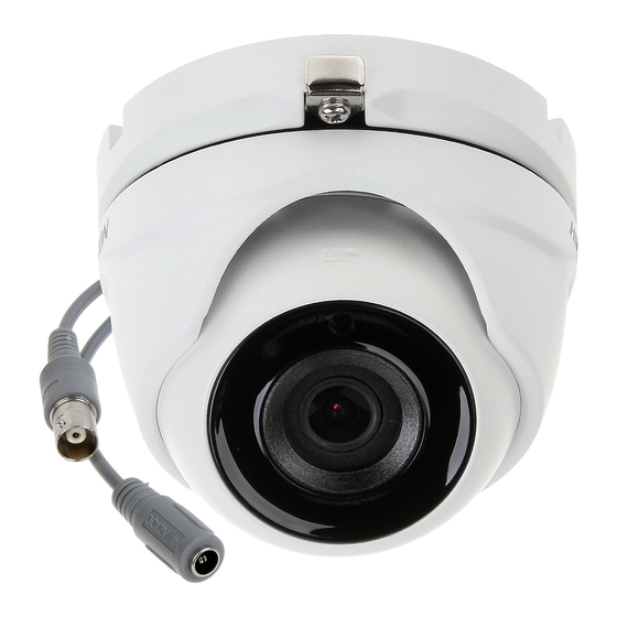
1.2.4 Type IV Camera Overview Clip Plate Mounting Base Trim Ring Enclosure Main Body Video Cable DC 12 V Power Cord Figure 1. 4 Type IV Camera Installation Installation Preparation Before you start: Make sure that the device in the package is in good ... - Page 7 Note: Cable hole is required when adopting ceiling outlet to route the cable. 3. Attach the mounting base of the type I camera to the ceiling and secure the camera with supplied screws. Figure 2. 2 Secure the Camera to the Ceiling Note: The supplied screw package contains self-tapping ...
- Page 8 2. Drill the screw holes according to the drill template, and the cable hole (optional) on the ceiling. Figure 2. 4 Drill Template Note: Cable hole is required when adopting ceiling outlet to route the cable. 3. Attach the mounting base of the type I camera to the ceiling and secure the camera with supplied screws.
- Page 9 Figure 2. 6 3-Axis Adjustment 1). Loosen the No.1 adjusting screw to adjust the pan position (0° to 360°). 2). Tighten the No.1 adjusting screw. 3). Loosen the No.2 adjusting screw to adjust the tilting position (0° to 180°). 4). Tighten the No. 2 adjusting screw. 5).
- Page 10 Note: Cable hole is required when adopting the ceiling outlet to route the cable. 4. Attach the mounting base to the ceiling and secure them with supplied screws Figure 2. 9 Attach the Mounting Base to the Ceiling Note: The supplied screw package contains self-tapping ...
- Page 11 Installation of Type IV Camera Before you start: Both wall mounting and ceiling mounting are suitable for the turret camera. Ceiling mounting will be taken as an example in this section. You can take steps of ceiling mounting as the reference, when adopting the wall mounting.
-
Page 12: Menu Description
Figure 1-4 Secure the Camera 8. Connect the corresponding cables, such as power cord, and video cable. 9. Power on the camera to check whether the image on the monitor is gotten from the optimum angle. If not, adjust the camera according to the figure below to get an optimum angle. -
Page 13: Video Format
BRIGHTNESS EXPOSURE MODE DWDR RETURN FORMAT MODE RETURN MODE LANGUAGE INFRARED DAY-NIGHT SMART IR RETURN IMAGE MODE MAIN MENU CONTRAST SHARPNESS VIDEO SETTINGS COLOR GAIN MIRROR RETURN RESET SAVE & EXIT Figure 3. 2 Main Menu Overview 5. Click the direction arrow to control the camera. Click up/down direction button to select the item. -
Page 14: Exposure Mode
Figure 3. 3 EXPOSURE BRIGHTNESS Brightness refers to the brightness of the image. You can set the brightness value from 1 to 10 to darken or brighten the image. The greater the value is, the brighter the image is. EXPOSURE MODE You can set the EXPOSURE MODE as GLOBAL, or BLC. -
Page 15: Video Settings
3.3.3 DAY/NIGHT COLOR, B/W (Black White), and SMART are selectable for DAY and NIGHT switches. COLOR The image is colored in day mode all the time. The image is black and white all the time. SMART The IR light turns on automatically as the environmental illumination becomes poor. -
Page 16: Color Gain
COLOR GAIN Adjust this feature to change the gain of the color. The value ranges from 1 to 10. DNR (Digital Noise Reduction) The DNR function can decrease the noise effect, especially when capturing moving images in poor light conditions, and delivering more accurate and sharper image.
Need help?
Do you have a question about the DS-2CE56D0T-ITME and is the answer not in the manual?
Questions and answers