Table of Contents
Advertisement
Quick Links
TURBO HD
TVI Bullet & Turret Camera
User Manual
User Manual
Thank you for purchasing our product. If there are any
questions, or requests, do not hesitate to contact the
dealer.
This manual applies to the model listed below.
Type
Model
Type I
DS-2CE16D0T-IR/IRP
Type II
DS-2CE56D0T-IRM
Type III
DS-2CE56D0T-IRP
This manual may contain several technically incorrect
places or printing errors, and the content is subject to
change without notice. The updates will be added to
the new version of this manual. We will readily improve
or update the products or procedures described in the
manual.
0200001080423
Advertisement
Table of Contents

Related Manuals for HIKVISION DS-2CE16D0T-IR/IRP


Summary of Contents for HIKVISION DS-2CE16D0T-IR/IRP
- Page 1 This manual applies to the model listed below. Type Model Type I DS-2CE16D0T-IR/IRP Type II DS-2CE56D0T-IRM Type III DS-2CE56D0T-IRP This manual may contain several technically incorrect places or printing errors, and the content is subject to change without notice.
-
Page 2: Regulatory Information
Regulatory Information FCC Information FCC compliance: This equipment has been tested and found to comply with the limits for a Class A digital device, pursuant to part 15 of the FCC Rules. These limits are designed to provide reasonable protection against harmful interference when the equipment is operated in a commercial environment. - Page 3 Safety Instruction These instructions are intended to ensure that user can use the product correctly to avoid danger or property loss. The precaution measure is divided into “Warnings” and “Cautions” Warnings: Serious injury or death may occur if any of the warnings are neglected.
-
Page 4: Product Features
The sensor may be burned out by a laser beam, so when any laser equipment is in using, make sure that the surface of sensor will not be exposed to the laser beam. Do not place the camera in extremely hot, cold, dusty ... -
Page 5: Installation Preparation
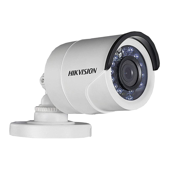
Figure 1. 2 Type II Camera Overview 1.2.3 Type III Camera Overview Main Body Enclosure Video Power Trim Ring Cable Cord Mounting Base Figure 1. 3 Type III Camera Overview Installation Installation Preparation Before you start: Make sure that the device in the package is in good ... - Page 6 3. Attach the mounting base of the type I camera to the ceiling and secure the camera with supplied screws. Figure 2. 2 Secure the camera to the ceiling Note: In the supplied screw package, both self-tapping screws and expansion blots are contained. If the wall is cement, expansion blots are required ...
- Page 7 1. Use the hex wrench to loosen the screw, and remove the mounting base from the camera body, shown as the figure 2.4. Figure 2. 4 Disassemble the Camera 2. Attach the drill template (supplied) to the place where you want to install the camera, and then drill the screw holes according to the drill template, and the cable hole (optional) on the ceiling.
- Page 8 Side Opening Clip Plate Figure 2. 7 Secure the Camera with Mounting Base 7. Connect the corresponding cables, such as power cord, and video cable. 8. Power on the camera to check whether the image on the monitor is gotten from the optimum angle. If not, adjust the camera according to the figure below to get an optimum angle.
- Page 9 Figure 2. 10 Attach the Mounting Base to the Ceiling Note: In the supplied screw package, both self-tapping screws and expansion blots are contained. If the wall is cement, expansion blots are required to fix the camera. If the wall is wooden, self-tapping screws are required.
-
Page 10: Menu Description
Pan Positioning Range: 0°to 360° Rotation Positioning Range: 0°to 360° Tilt Positioning Range: 0°to 75° Figure 2. 12 3-axis Adjustment Menu Description Purpose: Call the menu by clicking button on the PTZ Control interface, or call the preset No.95. Steps: 1. -
Page 11: Video Format
BRIGHTNESS EXPOSURE MODE DWDR RETURN FORMAT MODE RETURN MODE LANGUAGE INFRARED DAY-NIGHT SMART IR RETURN IMAGE MODE MAIN MENU CONTRAST SHARPNESS VIDEO SETTINGS COLOR GAIN MIRROR RETURN RESET SAVE & EXIT Figure 3. 2 Main Menu Overview 5. Click the direction arrow to control the camera. 4). - Page 12 Figure 3. 3 EXPOSURE BRIGHTNESS Brightness refers to the brightness of the image. You can set the brightness value from 1 to 10 to darken or brighten the image. The greater the value is, the brighter the image is. EXPOSURE MODE You can set the EXPOSURE MODE as GLOBAL, or BLC.
-
Page 13: Video Settings
3.4.3 DAY/NIGHT COLOR, B/W (Black White), and SMART are selectable for DAY and NIGHT switches. COLOR The image is colored in day mode all the time. The image is black and white all the time, and it is better to turn the INFRARED on in poor light conditions. SMART You can turn on/off the INFRARED, and set the value of SMART IR in this menu. -
Page 14: Color Gain
SHARPNESS Sharpness determines the amount of detail an imaging system can reproduce. You can set the SHARPNESS value from 1 to 10. COLOR GAIN Adjust this feature to change the gain of the color. The value ranges from 1 to 10. DNR (Digital Noise Reduction) The DNR function can decrease the noise effect, especially when capturing moving images in poor light...
Need help?
Do you have a question about the DS-2CE16D0T-IR/IRP and is the answer not in the manual?
Questions and answers