HIKVISION DS-2CE16C0T-IRPF User Manual
Turbo hd tvi bullet & turret camera
Hide thumbs
Also See for DS-2CE16C0T-IRPF:
- User manual (11 pages) ,
- User manual (14 pages) ,
- User manual (10 pages)
Advertisement
TURBO HD
TVI Bullet & Turret Camera
User Manual
UD03589B
User Manual
Thank you for purchasing our product. If there are any
questions, or requests, do not hesitate to contact the
dealer.
This manual applies to the model listed below.
Type
Type I
Type II
Type III
This manual may contain several technically incorrect
places or printing errors, and the content is subject to
change without notice. The updates will be added to
the new version of this manual. We will readily improve
or update the products or procedures described in the
manual.
Model
DS-2CE16C0T-IRF/IRPF
DS-2CE16D0T-IRF/IRPF
DS-2CE56C0T-IRMF
DS-2CE56D0T-IRMF
DS-2CE56C0T-IRF/IRPF
DS-2CE56D0T-IRF/IRPF
0100001061107
Advertisement
Table of Contents

Related Manuals for HIKVISION DS-2CE16C0T-IRPF


Summary of Contents for HIKVISION DS-2CE16C0T-IRPF
-
Page 1: User Manual
TURBO HD TVI Bullet & Turret Camera User Manual UD03589B User Manual Thank you for purchasing our product. If there are any questions, or requests, do not hesitate to contact the dealer. This manual applies to the model listed below. Type Model Type I... -
Page 2: Regulatory Information
Regulatory Information FCC Information FCC compliance: This equipment has been tested and found to comply with the limits for a Class A digital device, pursuant to part 15 of the FCC Rules. These limits are designed to provide reasonable protection against harmful interference when the equipment is operated in a commercial environment. - Page 3 Safety Instruction These instructions are intended to ensure that user can use the product correctly to avoid danger or property loss. The precaution measure is divided into “Warnings” and “Cautions” Warnings: Serious injury or death may occur if any of the warnings are neglected.
-
Page 4: Product Features
The sensor may be burned out by a laser beam, so when any laser equipment is in using, make sure that the surface of sensor will not be exposed to the laser beam. Do not place the camera in extremely hot, cold, dusty ... -
Page 5: Installation Preparation
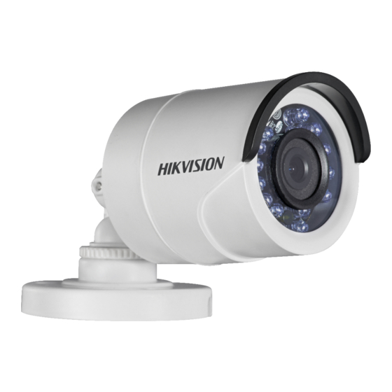
1.2.2 Type II Camera Overview Mounting Base Trim Ring Enclosure Switch Video Camera Button Cable Power Cord Figure 1. 2 Type II Camera Overview Note: Press the switch button for 5 seconds to switch the video output with TVI, AHD, CVI, and CVBS available. 1.2.3 Type III Camera Overview Main Body Enclosure... - Page 6 disassemble the camera for repair or maintenance by yourself. Installation of Type I Camera Steps: 1. Attach the dill template to the ceiling. 2. Drill the screw holes according to the drill template, and the cable hole (optional) on the ceiling. 47.6 Unit:...
- Page 7 3). Loosen the No.2 adjusting screw to adjust the tilting position (0° to 180°). 4). Tighten the No. 2 adjusting screw. 5). Loosen the No.3 adjusting screw to adjust the rotation position (0° to 360°). 6). Tighten the No.3 adjusting screw. 0°...
- Page 8 3. Attach the mounting base to the ceiling and secure them with supplied screws Figure 2. 6 Attach the Mounting Base to the Ceiling Note: In the supplied screw package, both self-tapping screws and expansion blots are contained. If the wall is cement, expansion blots are required ...
- Page 9 Installation of Type III Camera Steps: 1. Attach the drill template (supplied) to the place where you want to install the camera, and then drill the screw holes and the cable hole (optional) according to the drill template on the ceiling. Note: Cable hole is required when adopting ceiling outlet to route the cable.
- Page 10 Figure 2. 11 Secure the Camera with Mounting Base 5. Connect the corresponding cables, such as power cord, and video cable. 6. Power on the camera to check whether the image on the monitor is gotten from the optimum angle. If not, adjust the camera according to the figure below to get an optimum angle.
Need help?
Do you have a question about the DS-2CE16C0T-IRPF and is the answer not in the manual?
Questions and answers