Advertisement
Quick Links
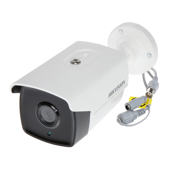
TURBO HD
TVI Bullet & Turret & Dome
Camera
User Manual
UD03600B
User Manual
Thank you for purchasing our product. If there are any
questions, or requests, do not hesitate to contact the
dealer.
This manual applies to the model listed below.
Type
Type I
Type II
Type III
This manual may contain several technically incorrect
places or printing errors, and the content is subject to
change without notice. The updates will be added to
the new version of this manual. We will readily improve
or update the products or procedures described in the
manual.
Model
DS-2CE16C0T-IT1F/3F/5F
DS-2CE16D0T-IT1F/3F/5F
DS-2CE56C0T-IT1F/3F
DS-2CE56D0T-IT1F/3F
DS-2CE56C0T-IRMMF
DS-2CE56D0T-IRMMF
0100001061107
Advertisement

Related Manuals for HIKVISION TURBO HD DS-2CE16C0T-IT1F


Summary of Contents for HIKVISION TURBO HD DS-2CE16C0T-IT1F
- Page 1 TURBO HD TVI Bullet & Turret & Dome Camera User Manual UD03600B User Manual Thank you for purchasing our product. If there are any questions, or requests, do not hesitate to contact the dealer. This manual applies to the model listed below. Type Model Type I...
-
Page 2: Regulatory Information
Regulatory Information FCC Information FCC compliance: This equipment has been tested and found to comply with the limits for a Class A digital device, pursuant to part 15 of the FCC Rules. These limits are designed to provide reasonable protection against harmful interference when the equipment is operated in a commercial environment. - Page 3 Safety Instruction These instructions are intended to ensure that user can use the product correctly to avoid danger or property loss. The precaution measure is divided into “Warnings” and “Cautions” Warnings: Serious injury or death may occur if any of the warnings are neglected.
- Page 4 The sensor may be burned out by a laser beam, so when any laser equipment is in using, make sure that the surface of sensor will not be exposed to the laser beam. Do not place the camera in extremely hot, cold, dusty ...
-
Page 5: Product Features
Introduction Product Features The camera is applicable for both indoor and outdoor conditions, and the application scenarios include road, warehouse, parking lot, office, campus etc.. The main features are as follows: High performance CMOS sensor 1080p/720p resolution Auto white balance ... -
Page 6: Installation Preparation
1.2.3 Type III Camera Overview Black Liner Adjusting Screw Camera Power Cord Bubble Video Cable Switch Button Figure 1. 3 Type III Camera Overview Note: Press the switch button for 5 seconds to switch the video output with TVI, AHD, CVI, and CVBS available. Installation Installation Preparation Before you start:... - Page 7 Note: Cable hole is required when adopting ceiling outlet to route the cable. 3. Attach the mounting base of the type I camera to the ceiling and secure the camera with supplied screws. Figure 2. 2 Secure the camera to the ceiling Note: In the supplied screw package, both self-tapping ...
- Page 8 Figure 2. 4 Disassemble the Camera 2. Remove the mounting base from the camera body with a flat object, e.g., a coin. 3. Attach the drill template (supplied) to the place where you want to install the camera, and then drill the screw holes and the cable hole (optional) on the ceiling according to the drill template.
- Page 9 Figure 2. 7 Secure the Camera with Mounting Base 7. Connect the corresponding cables, such as power cord, and video cable. 8. Power on the camera to check whether the image on the monitor is gotten from the optimum angle. If not, adjust the camera according to the figure below to get an optimum angle.
- Page 10 2-Φ4.5 Φ98.0 Figure 2. 10 Drill Template 3. Attach the mounting base to the ceiling and secure them with supplied screws Figure 2. 11 Attach the Mounting Base to the Ceiling 4. Route the cables through the cable hole (optional), or the side opening.