Advertisement
AUBER INSTRUMENTS
Instruction Manual
Caution
• This controller is intended to control equipment under normal operating
conditions. If failure or malfunction of it could lead to an abnormal operating
condition that could cause personal injury or damage to the equipment or other
property, other devices (limit or safety controls) or systems (alarm or
supervisory) intended to warn of or protect against failure or malfunction of the
controller must be incorporated into and maintained as part of the control
system.
• Installing the rubber gasket supplied will protect the controller front panel from
dust and water splash (IP54 rating). Additional protection is needed for higher
IP rating.
• This controller carries a 90-day warranty. This warranty is limited to the
controller only.
1. Features
• The PID control with artificial intelligent enhancement for precision temperature
control.
• Auto-tuning function can find the best PID parameter automatically.
• ON/OFF control mode for refrigerator, motor and solenoid valve control
application.
• Linear output control 0 ~ 20 mA or 4 ~ 20 mA.
• Bumpless transfer between Auto and Manual control mode.
• Optional serial communication port (RS-485/Modbus_RTU).
• The output can be set for linear output controller or relay contactor control by
the user.
• Support 10 different types of commonly used temperature sensor inputs.
2. Specifications
Thermocouple (TC): K, E, S, R, J, T, B, WRe3/25
Input type
RTD (Resistance temperature detector): Pt100, Cu50
Input range
See Table 2
Display
Dual lines, four digits, ° F or ° C
Display resolution
1° C, 1° F; or 0.1° C, 0.1° F with Pt100
Accuracy
± 0.2% or ± 1 unit of full input range
Control mode
PID, manual
Relay contact: 3 A at 240 VAC.
Output mode
Linear current output: 0 ~ 20 mA, 4 ~ 20 mA.
Alarm
Process high/low alarm
Power
< 2 Watt
consumption
Power supply
85 ~ 260 VAC / 50 ~ 60 Hz or 85 ~ 260 VDC
Communication
RS-485 (Modbus_RTU)
(optional)
Operating
0 ~ 50° C, ≤ 85% RH
condition
Mounting cutout
45 x 45 mm
Dimension
48 x 48 x 82 mm (1/16 DIN)
2021.05
SYL-2381-mA PID TEMPERATURE CONTROLLER
INSTRUCTION MANUAL
Version 1.3 (May, 2021)
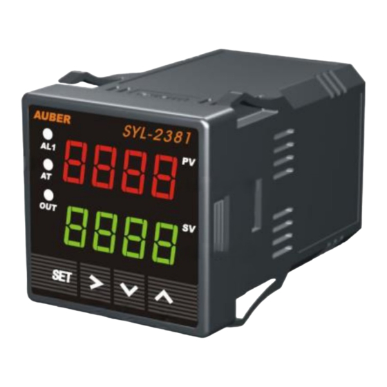
3. Front Panel and Operation
① AL1: Relay J1 output indicator.
AT: ON for manual mode. Blinking during auto-tuning process.
OUT: main output indicator.
② Up key: value increment / select the next parameter.
③ Down key: value decrement / select previous parameter.
④ Shift key: start auto tuning / shift digit / check output percentage*
⑤ Set key: confirm change / switch between Manual and Auto mode.
⑥ PV window: measured temperature, or, Process Value (PV)
⑦ SV window: set temperature, or, Set Value (SV)
Note *: Press Shift key momentarily to change the SV window from set
temperature to real-time output percentage. It will be display as "oXXX". For
example, "o 90" means the current output percentage is 90%. Press Shift key
again to switch back to set temperature.
4. Terminal Wiring (back view)
+
Figure 2. Terminal assignment of SYL-2381-mA.
WWW.AUBERINS.COM
Figure 1. Front panel
TC
mA
RTD
-
+ -
W
R
R
6
7
8
9
10
11
13
12
14
2
4
5
1
3
Po wer
J1
AC/DC
85-260V
P1/7
Advertisement
Table of Contents

Related Manuals for Auber Instruments SYL-2381-mA


Summary of Contents for Auber Instruments SYL-2381-mA
- Page 1 Communication RS-485 (Modbus_RTU) (optional) Operating 0 ~ 50° C, ≤ 85% RH Po wer condition AC/DC 85-260V Mounting cutout 45 x 45 mm Figure 2. Terminal assignment of SYL-2381-mA. Dimension 48 x 48 x 82 mm (1/16 DIN) 2021.05 P1/7...
-
Page 2: Output Connection
AUBER INSTRUMENTS WWW.AUBERINS.COM 4.1 Sensor connection 4.4.2 The J1 relay is “dry single pole switch”. It does not provide power by itself. 4.1.1 Thermocouple Figure 11 shows how the J1 relay is wired to pass the 120 V AC power to drive an The thermocouple should be connected to terminals 9 and 10. -
Page 3: Control Parameters
“4-20” - Main output is set to 4 - 20 mA linear current output mode. cause oscillation, or even make the system non-convergent. “SSR” - Not available on SYL-2381-mA. Note 4. Hysteresis Band Hy (also called dead band, or differential) is used in on/off 5.3 Control parameters... - Page 4 AUBER INSTRUMENTS WWW.AUBERINS.COM Table 4. Control parameters. a. In the normal operation mode, press or V key to directly increase or Symbol Description Setting Range Initial Note decrease the SV. Then wait about 4 seconds to allow the controller save the new...
-
Page 5: Auto Tuning
9. Serial communication control will resume PID control with previous PID parameters. 6.3 In SYL-2381-mA. auto-tune can be used for J1 relay as main output modes RS485 serial communication is an optional feature available on SYL-2381-mA-S. (OUTY = 3 or 4) and linear output as main output modes (OUTY = 1 or 2). When It complies with the widely-accepted MODBUS_RTU protocol. - Page 6 AUBER INSTRUMENTS WWW.AUBERINS.COM b. Parameter settings. These are the parameters that need to be changed from the initial value: outy = 3 for PID mode with J1 relay output; ot = 20 to avoid switching the contactor too often; for target temperature set SV = 1200° F.
- Page 7 Copyright © 2021 Auber Instruments Inc. All rights reserved. No part of this datasheet shall be copied, reproduced, or transmitted in any way without the prior, written consent of Auber Instruments. Auber Instruments retains the exclusive rights to all information included in this document.
Need help?
Do you have a question about the SYL-2381-mA and is the answer not in the manual?
Questions and answers