Advertisement
AUBER INSTRUMENTS
Instruction Manual
Caution
• This controller is intended to control equipment under normal operating
conditions. If failure or malfunction of it could lead to an abnormal operating
condition that could cause personal injury or damage to the equipment or other
property, other devices (limit or safety controls) or systems (alarm or
supervisory) intended to warn of or protect against failure or malfunction of the
controller must be incorporated into and maintained as part of the control
system.
• Installing the rubber gasket supplied will protect the controller front panel from
dust and water splash (IP54 rating). Additional protection is needed for higher
IP rating.
• This controller carries a 90-day warranty. This warranty is limited to the
controller only.
1. Features
• The PID control with artificial intelligent enhancement for precision temperature
control.
• Auto-tuning function can find the best PID parameter automatically.
• On/off control mode for refrigerator, motor and solenoid valve control
application.
• Bumpless transfer between Auto and Manual control.
• Limit control for safety protection and special applications.
• The output can be set for SSR output control or relay contactor control by the
user.
• Two contact relays can be configured as one PID and one alarm output, dual
alarm outputs, or dual On/off control.
• Support 10 different types of commonly used temperature sensor inputs.
2. Specification
Thermocouple (TC): K, E, S, R, J, T, B, WRe3/25
Input type
RTD (Resistance temperature detector): Pt100, Cu50
Input range
See table 2
Display
Dual lines, four digits, ° F or ° C
Display
1° C, 1° F; or 0.1° C, 0.1° F with Pt100
resolution
Accuracy
± 0.2% or ± 1 unit of full input range
Control mode
PID, On-off. Limit, Manual
Output mode
Relay contact: 3A at 240VAC, SSR: 8VDC, 12 mA.
Alarm
Process high/low alarm
Power
<2 Watt
consumption
Power supply
85~260VAC/50~60Hz or 85-360VDC
Sample rate
4 samples/sec
Operating
0 ~ 50 ° C, ≤85%RH
condition
Mounting cutout
45 x 45 mm
Dimension
48x48x75mm (1/16 DIN)
2021.10
SYL-2362A2 PID TEMPERATURE CONTROLLER
INSTRUCTION MANUAL
Version 2.6 (Oct, 2021)
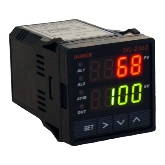
3. Front Panel and Operation
① AL-1 Relay J1 output indicator
AL-2 Relay J2 output indicator
AT/M- On for manual mode. Blinking during auto-tuning process
OUT- SSR output indicator
② Value increment/Select next parameter
③ Value decrement/Select previous parameter
④ Auto tuning/Digit shift
⑤ Set/Confirm/Manual Auto switching/Reset (for Limit control mode)
⑥ Measured temperature, or, Process Value (PV)
⑦ Set temperature, or, Set Value (SV)
4. Terminal Wiring (back view)
4.1 Sensor connection
4.1.1 Thermocouple
The thermocouple should be connected to terminals 9 and 10. Make sure that
polarity is correct. There are two commonly used color codes for the K type
thermocouple. US color code uses yellow (positive) and red (negative). Imported
DIN color code uses red (positive) and green/blue (negative). The temperature
reading will decrease as temperature increases if the connection is reversed.
WWW.AUBERINS.COM
Figure 1. Front panel
W
R
R
NC
NO
Po wer
NC
NO
AC/DC
85-260V
Figure 2. Wiring diagram
P1/6
Advertisement
Table of Contents

Related Manuals for Auber Instruments SYL-2362A2


Summary of Contents for Auber Instruments SYL-2362A2
- Page 1 AUBER INSTRUMENTS WWW.AUBERINS.COM Instruction Manual SYL-2362A2 PID TEMPERATURE CONTROLLER INSTRUCTION MANUAL Version 2.6 (Oct, 2021) 3. Front Panel and Operation Caution • This controller is intended to control equipment under normal operating conditions. If failure or malfunction of it could lead to an abnormal operating...
-
Page 2: Output Connection
AUBER INSTRUMENTS WWW.AUBERINS.COM 4.1.2 RTD sensor SSR output should be wired. When switching a North American 240VAC power, For a three-wire RTD with standard DIN color code, the two red wires should be the heater will be live even when the SSR is off. Users should install a double pole connected to the terminals 9 and 10. - Page 3 AUBER INSTRUMENTS WWW.AUBERINS.COM Table 2. Temperature sensor code Table 3. PID and relevant parameters Setting Symbol Description Working Temperature Range Symbol Description Initial Note Range TC, Type T -200~400° C; -320~752° F Proportional 0.1~99.9(%) TC, Type R -50~1600° C; -58~2900° F...
-
Page 4: On/Off Control Mode
AUBER INSTRUMENTS WWW.AUBERINS.COM Table 4. Temperature and alarm parameters Initial Symbol Description Note Setting AT end AT start AT calculation Target temperature (Set Value) J1 on temperature J1 off temperature J2 on temperature ON OFF ON OFF J2 off temperature... -
Page 5: Application Example
AUBER INSTRUMENTS WWW.AUBERINS.COM mode, press and hold SET key until the “AT/M” indicator turned off. This controller the “AT” stops blinking, the new PID parameters are generated for the system. offers “bumpless” switch from the PID to manual mode. If the controller outputs The controller is in normal operation mode. -
Page 6: Error Message And Trouble Shooting
RTD sensor, check the input setting first because most No part of this datasheet shall be copied, reproduced, or transmitted in any way without the prior, written consent of Auber Instruments. Auber Instruments retains controllers are shipped with input set for thermocouple. Then check the wiring. The the exclusive rights to all information included in this document.
Need help?
Do you have a question about the SYL-2362A2 and is the answer not in the manual?
Questions and answers