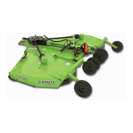
Schulte 2 Series Operator's Manual

Schulte 2 Series Operator's Manual

Rotary cutter
Hide thumbs Also See for 2 Series:
Table of Contents

Advertisement

Quick Links

FX-318/FX-212 SERIES 2
Published 08/21
This Operator's Manual is an
integral part of the safe operation
of this machine and must be
maintained with the unit at all
times. READ, UNDERSTAND, and
FOLLOW
Operation Instructions contained
in this manual before operating
the equipment. C01-Cover_S
Schulte Industries Ltd.
PO Box 70
Englefeld Saskatchewan
Canada S0K 1N0
Tel. (306) 287-3715
Fax. (306) 287-3355
Parts Fax. (306) 287-4066
Web: www.schulte.ca
Rotary Cutter
S/N C31820801108-C31820827108
S/N C31920022108-C31920024108
OPERATOR'S MANUAL
the
Safety
©2021 Alamo Group Inc.
Important
Operating
and
Instructions are found
in the Mower Safety
Video
that
can
instantly accessed on
and
the
internet
www.algqr.com/sve
Part No. C319-010C
Safety
be
at:
$0.00

Advertisement

Table of Contents
loading

Summary of Contents for Schulte 2 Series

  • Page 1 FOLLOW Safety internet Operation Instructions contained www.algqr.com/sve in this manual before operating the equipment. C01-Cover_S Schulte Industries Ltd. PO Box 70 Englefeld Saskatchewan Canada S0K 1N0 Tel. (306) 287-3715 Fax. (306) 287-3355 Parts Fax. (306) 287-4066 Web: www.schulte.ca $0.00...
  • Page 3 In order to reduce accidents and enhance the safe operation of mowers, Schulte, in cooperation with other industry manufacturers has developed the AEM/FEMA Industrial and Agricultural Mower Safety Practices video and guide book. The video will familiarize and instruct mower-tractor operators in safe practices when using industrial and agricultural mowing equipment.
  • Page 4 Schulte Industries LTD. is willing to provide one (1) AEM Mower Safety Practices Video Please Send Me: VHS Format – AEM/FEMA Mower Operator Safety Video DVD Format – AEM/FEMA Mower Operator Safety Video Mower Operator’s Manual AEM Mower Operator’s Safety Manual...
  • Page 5 A Manual canister is provided on the implement where this manual can be properly stored. If you lose or damage this manual a free replacement manual can be obtained from an authorized Schulte dealer or www.schulte.ca...
  • Page 6 DEALER to CUSTOMER Pre-Delivery/ Operation Instructions Dealer should inform the Purchaser of this product of Warranty terms, provisions, and procedures that are applicable. Dealer should inform Purchaser to review the contents of the Operator’s Manual including safety equipment, safe operation and maintenance, to review the Safety Signs on the implement (and tractor if possible) and of Purchaser’s responsibility to train his/her operators’s of safe operation procedures.
  • Page 7: Table Of Contents

    Table of Contents SAFETY SECTION ..................1-1 GENERAL SAFETY INSTRUCTIONS AND PRACTICES ................1-2 OPERATOR SAFETY ............................1-3 CRUSHING HAZARDS ............................. 1-4 CONNECTING OR DISCONNECTING IMPLEMENT SAFETY ................ 1-5 THROWN OBJECTS HAZARDS ........................1-6 RUN OVER HAZARDS ............................1-8 PTO ENTANGLEMENT HAZARDS ........................1-9 MOWER BLADE CONTACT HAZARDS ......................
  • Page 8 ROPS and Seat Belt ............................4-4 Tractor Safety Devices ............................4-4 Tractor Horsepower ............................4-4 Drawbar-Pull Type Mower ..........................4-5 Tractor Hydraulics ..............................4-5 Front End Weight ..............................4-5 Power Take Off (PTO) ............................4-5 Tire Spacing ...............................4-6 GETTING ON AND OFF THE TRACTOR ......................4-6 Boarding the Tractor ............................4-6 Dismounting the Tractor ............................4-7 STARTING THE TRACTOR ..........................4-8 CONNECTING THE CUTTER TO THE TRACTOR ...................4-8...
  • Page 9 Drivelines ................................5-9 Tractor Shaft ..............................5-9 SLIP CLUTCHES ............................. 5-10 Disassembly ..............................5-10 Reassembly ..............................5-11 BLADE REMOVAL ............................5-14 Blade Installation ..............................5-15 Blade Bolt Inspection ............................5-15 BLADE CARRIER REMOVAL ......................... 5-16 Blade Carrier Installation ..........................5-16 HUBS & SPINDLES ............................5-17 Tightening Instructions for 517 &...
  • Page 11: Safety Section

    SAFETY SECTION Safety Section 1-1 © 2021 Alamo Group Inc.
  • Page 12: General Safety Instructions And Practices

    SAFETY GENERAL SAFETY INSTRUCTIONS AND PRACTICES A careful operator is the best operator. Safety is of primary importance to the manufacturer and should be to the owner/operator. Most accidents can be avoided by being aware of your equipment, your surroundings, and observing certain precautions.
  • Page 13: Operator Safety

    SAFETY OPERATOR SAFETY TO AVOID DEATH OR SERIOUS INJURY DO THE FOLLOWING: • READ, UNDERSTAND and FOLLOW Operator's Manual instructions, Warnings and Safety Messages. WEAR SAFETY GLASSES with side shields (marked with ANSI Z87), safety shoes, hard hat, hearing • protection and gloves when operating or repairing equipment •...
  • Page 14: Crushing Hazards

    SAFETY CRUSHING HAZARDS TO AVOID DEATH OR SERIOUS INJURY FROM FALLING OFF TRACTOR, EQUIPMENT RUN OVER, ROLLOVER AND CRUSHING BY FALLING WING OR IMPLEMENT: • USE ROPS and SEAT BELT equipped tractors for mowing operations. • KEEP ROPS lock in up position. •...
  • Page 15: Connecting Or Disconnecting Implement Safety

    SAFETY CONNECTING OR DISCONNECTING IMPLEMENT SAFETY TO AVOID DEATH OR SERIOUS INJURY FROM BEING CRUSHED BY TRACTOR OR IMPLEMENT: WHEN BACKING tractor to implement hitch: • DO NOT ALLOW BYSTANDERS between tractor and implement. BEFORE connecting and disconnecting implement hitch: •...
  • Page 16: Thrown Objects Hazards

    SAFETY THROWN OBJECTS HAZARDS ROTARY MOWERS CAN THROW OBJECTS 300 FEET OR MORE UNDER ADVERSE CONDITIONS. TO AVOID DEATH OR SERIOUS INJURY TO OPERATOR OR BYSTANDERS FROM THROWN OBJECTS: • KEEP bystanders 300 feet away STOP MOWING IF PASSERSBY ARE WITHIN 300 FEET UNLESS: •...
  • Page 17 SAFETY THROWN OBJECTS HAZARD (CONTINUED) MOWER OPERATION: • DO NOT exceed mower's rated Cutting Capacity or cut non-vegetative material. • USE ENCLOSED TRACTOR CABS when two or more mowers are operating in mowing area. Do Not mow in areas where bees or insects may attack unless you WEAR PROTECTIVE CLOTHING or •...
  • Page 18: Run Over Hazards

    SAFETY RUN OVER HAZARDS TO AVOID DEATH OR SERIOUS INJURY FROM FALLING OFF TRACTOR OR EQUIPMENT RUN OVER: • USE ROPS and SEAT BELT equipped tractors for mowing operations. • KEEP ROPS locked in UP position. • ONLY start tractor while seated in tractor seat. ALWAYS BUCKLE UP seat belt when operating tractor and equipment.
  • Page 19: Pto Entanglement Hazards

    SAFETY PTO ENTANGLEMENT HAZARDS KEEP AWAY FROM ROTATING DRIVELINES AND ELEMENTS TO AVOID DEATH OR SERIOUS INJURY: hands, feet and body AWAY from rotating blades, drivelines and parts until all moving STAY AWAY KEEP elements have stopped. • STOP, LOOK and LISTEN before approaching the mower to make sure all rotating motion has stopped. ROTATING COMPONENTS CONTINUE to ROTATE after the PTO is shut off.
  • Page 20: Mower Blade Contact Hazards

    SAFETY MOWER BLADE CONTACT HAZARDS KEEP AWAY FROM ROTATING BLADES TO AVOID DEATH OR SERIOUS INJURY FROM BLADE CONTACT: • STAY AWAY and KEEP HANDS, FEET and BODY AWAY from rotating blades, drivelines and parts until all moving elements have stopped. •...
  • Page 21: High Pressure Oil Leak Hazard

    SAFETY HIGH PRESSURE OIL LEAK HAZARD TO AVOID DEATH OR SERIOUS INJURY FROM HIGH PRESSURE HYDRAULIC OIL LEAKS PENERATING SKIN: • equipment with oil or fuel leaks. DO NOT OPERATE • all hydraulic hoses, lines and connections in before applying system KEEP GOOD CONDITION TIGHT...
  • Page 22: Electrical & Fire Hazards

    SAFETY ELECTRICAL & FIRE HAZARDS TO AVOID DEATH OR SERIOUS INJURY FROM ELECTRICAL CONTACT WHEN WORKING AROUND ELECTRICAL POWER LINES, GAS LINES AND UTILITY LINES: • INSPECT mowing area for overhead or underground electrical power lines, obstructions, gas lines, cables and Utility, Municipal, or other type structure. •...
  • Page 23: Transporting Hazards

    SAFETY TRANSPORTING HAZARDS TO AVOID DEATH OR SERIOUS INJURY WHEN TOWING OR TRANSPORTING EQUIPMENT: • KEEP transport speed BELOW 20 mph to maintain control of equipment. REDUCE SPEED on inclines, on turns and in poor towing conditions. • • DO NOT TOW with trucks or other vehicles. •...
  • Page 24: Hazards With Maintenance Of Implement

    SAFETY HAZARDS WITH MAINTENANCE OF IMPLEMENT AVOID DEATH OR SERIOUS INJURY FROM COMPONENT FAILURE BY KEEPING IMPLEMENT IN GOOD OPERATING CONDITION IN PERFORMING PROPER SERVICE, REPAIRS AND MAINTENANCE. BEFORE PERFORMING SERVICE, REPAIRS AND MAINTENANCE ON THE IMPLEMENT: SECURE EQUIPMENT FOR SERVICE BLOCK OUT POTENTIAL ENERGY HAZARDS;...
  • Page 25: Hazards With Maintenance Of Implement - (Continued)

    SAFETY HAZARDS WITH MAINTENANCE OF IMPLEMENT - (CONTINUED) AVOID DEATH OR SERIOUS INJURY FROM COMPONENT FAILURE BY KEEPING IMPLEMENT IN GOOD OPERATING CONDITION IN PERFORMING PROPER SERVICE, REPAIRS AND MAINTENANCE. PERFORM SERVICE, REPAIRS, LUBRICATION AND MAINTENANCE OUTLINED IN IMPLEMENT MAINTENANCE SECTION: •...
  • Page 26 These parts are made and tested to Schulte Industry specifications. Non-genuine "will fit" parts do not consistently meet these specifications. The use of “will fit” parts may reduce the performance, void Schulte warranties, and present a safety hazard. Use genuine Schulte parts for economy and safety.
  • Page 27: Decal Location

    SAFETY Decal Location NOTE: Schulte supplies safety decals on this product to promote safe operation. Damage to the decals may occur while in shipping, use, or reconditioning. Schulte cares about the safety of its customers, operators, and bystanders, and will replace the safety decals on this product in the field, free of charge (Some shipping and handling charges may apply).
  • Page 28 SAFETY FX-318 - FX212 08/21 Safety Section 1-18 © 2021 Alamo Group Inc.
  • Page 29 FEMA Member 226-081 IMPORTANT Check Oil Level 226-088 IMPORTANT 1000 RPM 226-100 SERIAL PLATE Serial Plate 226-117 LOGO Schulte, Medium Profile 226-118 LOGO Schulte, Large Profile 226-153 REFLECT Red Reflector, 2”x9” 226-154 REFLECT Amber Reflector, 2”x9” 226-1541 REFLECT Amber Reflector, 2”x4-1/2”...
  • Page 30: Decal Description

    SAFETY Decal Description FX-318 - FX212 08/21 Safety Section 1-20 © 2021 Alamo Group Inc.
  • Page 31 SAFETY FX-318 - FX212 08/21 Safety Section 1-21 © 2021 Alamo Group Inc.
  • Page 32 SAFETY FX-318 - FX212 08/21 Safety Section 1-22 © 2021 Alamo Group Inc.
  • Page 33 SAFETY FX-318 - FX212 08/21 Safety Section 1-23 © 2021 Alamo Group Inc.
  • Page 34 SAFETY FX-318 - FX212 08/21 Safety Section 1-24 © 2021 Alamo Group Inc.
  • Page 35 SAFETY FX-318 - FX212 08/21 Safety Section 1-25 © 2021 Alamo Group Inc.
  • Page 36 SAFETY FX-318 - FX212 08/21 Safety Section 1-26 © 2021 Alamo Group Inc.
  • Page 37 SAFETY FX-318 - FX212 08/21 Safety Section 1-27 © 2021 Alamo Group Inc.
  • Page 38 SAFETY FX-318 - FX212 08/21 Safety Section 1-28 © 2021 Alamo Group Inc.
  • Page 39 SAFETY FX-318 - FX212 08/21 Safety Section 1-29 © 2021 Alamo Group Inc.
  • Page 40 SAFETY FX-318 - FX212 08/21 Safety Section 1-30 © 2021 Alamo Group Inc.
  • Page 41: Federal Laws And Regulations

    SAFETY FEDERAL LAWS AND REGULATIONS This section is intended to explain in broad terms the concept and effect of federal laws and regulations concerning employer and employee equipment operators. This section is not intended as a legal interpretation of the law and should not be considered as such.
  • Page 43: Introduction Section

    INTRODUCTION SECTION Introduction Section 2-1 © 2021 Alamo Group Inc.
  • Page 44 INTRODUCTION We are pleased to have you as a Schulte customer. Your Rotary Cutter has been carefully designed with care and built with quality materials by skilled workers to give maximum service with minimum down time. This manual is provided to give you the necessary operating and maintenance instructions for keeping your rotary cutter in top operating condition.
  • Page 45: Equipment Specifications

    INTRODUCTION The FX318/FX212 heavy duty rotary Cutter is designed primarily for weeds, grass, and brush to 3-1/2” diameter. The side skirts are 13-5/8” deep. This additional room under the deck, along with high blade tip speeds allows for a better cut and better material flow. The one piece center shield allows for easy and full access to drivelines, clutches and gearboxes on the center section.
  • Page 46: Key Operation Points

    ALWAYS OPERATE WITH THE WING HYDRAULIC CYLINDER CONTROL VALVES IN A FLOAT POSITION. • For maximum performance and service life, Always use Genuine Schulte replacement parts. Operating Noise Level/Sound Pressure The sound levels at the operator's ear from the attached machine (rotary cutter) are at least 10 dB(A) below the levels from typical Agricultural tractors used to power and transport this machine.
  • Page 47 GENERAL STATEMENT AFFECTING ALL SCHULTE WARRANTY Schulte Industries Ltd. warrants to the original purchaser only, that in the event of any defect in material or workmanship in the product sold by Schulte Industries, the subject of this warranty (“the goods”) during the warranty period mentioned below the manufacturer will provide the coverage specified below.
  • Page 48 • The Dealer must keep the failed part until the claim is processed, to allow Schulte Industries the option of further examination of the part. Further examination may mean that pictures are sent, or that the part be returned to Schulte.
  • Page 49: Assembly Section

    ASSEMBLY SECTION Assembly Section 3-1 © 2021 Alamo Group Inc.
  • Page 50: General Assembly

    ASSEMBLY GENERAL ASSEMBLY Check oil level in all gearboxes before operation. Refer to the ‘Lubrication’ section of this manual for recommended oil type and viscosity. Lubricate all grease fittings. Refer to the grease schedule in this manual. Check that all nuts and bolts are in place and properly tightened.
  • Page 51: Chain Guards

    ASSEMBLY Chain Guards The FX-318/FX-212 comes standard with single or double chain guards. Use the Parts Manual for chain guard locations on the rotary cutter. If your machine is equipped with single safety chains insert the first link of the 5 link chain into the first slot of the chain rail.
  • Page 52: Hydraulic Circuits

    ASSEMBLY HYDRAULIC CIRCUITS Adjust the hoses in the hose organizer to allow sufficient slack for turning. Ensure the hoses will not contact the driveline, will not bind while turning or can become pinched. Route the left wing hoses over the center lock bar and fasten to the hose clamp. Wrap the hose sections into hook-and-loop hose wrap.
  • Page 53: Hydraulic Lift System

    ASSEMBLY HYDRAULIC LIFT SYSTEM The hydraulic Lift System requires one single acting hydraulic circuit for operation. The system is comprised of one hydraulic cylinder with depth stop collar, and allows all wheels to be raised and lowered simultaneously. Before operation all air must be purged from the hydraulic lift circuit. Fully raise the cutter and hold the tractor’s hydraulic control lever forward for 5 minutes to allow oil to fully circulate through the hydraulic circuit.
  • Page 54: Precision Clevis- C000-360

    ASSEMBLY PRECISION CLEVIS– C000-360 Adjust the opening of the precision clevis by shimming the wear plate with the spacers. Remove the two 5/8” bolts and lockwashers and stack the spacers between the wear plate and the hitch block until the opening measures less than 1/8” taller than the drawbar.
  • Page 55: Installation Of Lights

    ASSEMBLY Installation of Lights Lock the rotary cutter into transport position. Bolt the light frames to the center beam using the supplied 3/8” bolts, washers and locknuts. Install the lamps onto the light frames with the amber light to the outside of the cutter. The red lamp is to be installed with the red facing the rear.
  • Page 56: Gearbox Layout & Blade Rotation

    ASSEMBLY GEARBOX LAYOUT & BLADE ROTATION CW Pan Machine - 540 RPM CW Pan Machine - 1000 RPM FX-318 - FX212 08/21 Assembly Section 3-8 © 2021 Alamo Group Inc.
  • Page 57: Gearbox Layout & Blade Rotation

    ASSEMBLY GEARBOX LAYOUT & BLADE ROTATION CCW Pan Machine - 540 RPM CCW Pan Machine - 1000 RPM FX-318 - FX212 08/21 Assembly Section 3-9 © 2021 Alamo Group Inc.
  • Page 58: Assembly From Truck Shipment

    ASSEMBLY Assembly from Truck Shipment The following are instructions to set up a FX-318/ FX-212 cutter that has been delivered on a truck. When the cutter is received the hitch will be flipped back onto the cutter as shown on Figure AsmP-R- 0465.
  • Page 59: Operation Section

    OPERATION SECTION Operation Section 4-1...
  • Page 60 SCHULTE FX-318/FX-212 ROTARY CUTTER OPERATION INSTRUCTIONS Schulte FX-318/FX-212 rotary cutters are manufactured with quality material by skilled workers. These cutters are designed to cut grass, weeds, crop stalks, brush and other vegetation up to 4” diameter. The cutter is equipped with protective deflectors and/or chain guards to prevent objects being thrown from the cutter by the blades, however, no shielding is 100% effective.
  • Page 61: Operator Requirements

    OPERATION 1. OPERATOR REQUIREMENTS Safe operation of the unit is the responsibility of a qualified operator. A qualified operator has read and understands the implement and tractor Operator’s Manuals and is experienced in implement and tractor operation and all associated safety practices. In addition to the safety messages contained in this manual, safety signs are affixed to the implement and tractor.
  • Page 62: Tractor Requirements

    OPERATION 2. TRACTOR REQUIREMENTS The tractor used to operate the cutter must have the power capacity to lift, pull, and operate the Power Take Off (PTO) at the cutter’s rated speed while traveling at a ground speed between 2 and 5 MPH. Operating the cutter with a tractor that does not meet the following requirements may cause tractor or cutter damage and be a potential danger to the operator and passersby.
  • Page 63: Drawbar-Pull Type Mower

    OPERATION 2.4 Drawbar-Pull Type Mower Position the length of the drawbar from the end of the tractor PTO shaft to the drawbar hitch hole according to the operating speed of the cutter. If the cutter is a 540 RPM unit, position the drawbar length from shaft end to hitch hole at 14”.
  • Page 64: Tire Spacing

    OPERATION Never operate the Tractor and Mower if the Implement input driveline is directly connected to the Tractor transmission. Tractor braking distances can be substantially increased by the momentum of the rotating Mower blades driving the Tractor transmission even though the Tractor clutch has been disengaged.
  • Page 65: Dismounting The Tractor

    OPERATION Never allow children to operate, ride on, or come close to the Tractor or Implement. Usually, 16-17 year-old children who are mature and responsible can operate the implement with adult supervision, if they have read and understand the Operator’s Manuals, been trained in proper operation of the tractor and Implement, and are physically large enough to reach and operate the controls easily.
  • Page 66: Starting The Tractor

    OPERATION 4. STARTING THE TRACTOR The operator must have a complete understanding of the placement, function, and operational use of all tractor controls before starting the tractor. Review the tractor operator’s manual and consult an authorized dealer for tractor operation instructions if needed. Essential Tractor Controls: •...
  • Page 67: Connecting The Mower Tongue To The Tractor

    OPERATION Always shut the Tractor completely down, place the transmission in park, and set the parking brake before you or anyone else attempts to connect or disconnect the Implement and Tractor hitches. (S3PT-15) 5.1 Connecting the Mower Tongue to the Tractor 1.
  • Page 68: Safety Tow Chain

    OPERATION 5.2 Safety Tow Chain If the implement is towed on a public roadway, a safety chain with tensile strength equal to or greater than the gross weight of the implement must be connected between the tractor and implement. This will help control the implement in the event the tongue becomes disconnected from the drawbar.
  • Page 69: Setting The Mower

    OPERATION 5.4 Lowering the Cutter Transport lock bar is provided for the center lift cylinder and a ball valve is provided on the wing lift circuit. When the transport lock bar is used on the center lift cylinder it prevents the mower from suddenly dropping due to a hydraulic cylinder or hose failure.
  • Page 70: Leveling Wing

    OPERATION Setting Cutting Height The cut height for the center section is set by extending or shortening the depth collar located on the center lift cylinder. Depth Adjustment Collar The cutter should always be operated in the highest position that will produce the desired cutting results.
  • Page 71 OPERATION 6.2 Setting Deck Pitch Mower should operated with deck approximately 3/4" HIGHER IN THE FRONT THAN THE REAR. Operating the mower at this pitch will allow the mower to cut the grass twice and can result in a more even cut and improved distribution of the cut material.
  • Page 72: Driveline Attachment

    OPERATION 7. DRIVELINE ATTACHMENT The driveline yoke and tractor PTO shaft must be dirt free and greased for attachment. To connect the mower driveline to the tractor PTO output shaft, twist the driveline yoke collar and align the grooves and splines of the yoke with those of the PTO shaft.
  • Page 73 OPERATION • Measure the distance from the mark to the end of the inner profile. This length is the amount the driveline profiles were engaged. • If the engaged length is less than 6”, the shaft is considered too short and should be replaced with a longer shaft.
  • Page 74: Constant Velocity (Cv) Driveline

    OPERATION 7.1 Constant Velocity (CV) Driveline For mowers equipped with a Constant Velocity (CV) driveline, the maximum turning angle between the tractor and mower must be determined to ensure the joint angle does not over-extend which can cause CV joint damage.
  • Page 75: Pre-Operation Inspection And Service

    OPERATION 8. PRE-OPERATION INSPECTION AND SERVICE Before each use, a pre-operation inspection and service of the implement and tractor must be performed. This includes routine maintenance and scheduled lubrication, inspecting that all safety devices are equipped and functional, and performing needed repairs. DO NOT operate the unit if the pre-operation inspection reveals any condition affecting safe operation.
  • Page 76: Tractor Pre-Operation Inspection/Service

    OPERATION 8.1 Tractor Pre-Operation Inspection/Service Refer to the tractor operator’s manual to ensure a complete pre-operation inspection and scheduled service performed according manufacturers recommendations. The following are some of the items that require daily service and inspection: • Tire condition/air pressure •...
  • Page 77 OPERATION The operator’s manual and safety signs affixed on the unit contain important instructions on the safe and proper use of the equipment. Maintain these important safety features on the implement in good condition to ensure the information is available to the operator at all times.
  • Page 78 OPERATION • Ensure the tractor PTO master shield is in place, lowered and in good condition. • Ensure each mower slip clutch shield is secured in place and in good condition. • Ensure the driveline slip clutch friction plates are not frozen together.
  • Page 79 OPERATION • Ensure that the mower is equipped and secured with wing transport locks. • Check the condition of the wing hinge pins. • Check the condition of the mower axle suspension spring. • Inspect mower tire condition, wheel bearings, and lug nut torque.
  • Page 80: Cutting Component Inspection

    OPERATION 8.3 Cutting Component Inspection Inspect blade pan and blade assembly for the following: OPS-U-0031 FX-318 - FX212 08/21 Operation Section 4-22 © 2021 Alamo Group Inc.
  • Page 81 OPERATION Operating the mower with loose blade hardware will damage the blade holder or blades and can result in blade breakage or blade fastener failure. Broken blades or bolts can be thrown out from under the mower for distances up to 300 feet. When the blades are replaced, the fastening hardware must be replaced.
  • Page 82: Blade Bolt Inspection

    OPERATION 8.4 Blade Bolt Inspection Inspect Blade Bolt Head daily for wear as followed: Inspect the Blade Bolt Heads daily for abnormal wear. REPLACE BOTH BLADE BOLTS on the Blades IMMEDIATELY if either blade bolts has: • Visible cracks or •...
  • Page 83 OPERATION Rotary Mower PRE-OPERATION Inspection ______________________ Mower ID# IMPORTANT: Scan this Date:___________________________________ QR Code for an electronic Make:__________________________________ copy of this inspection Shift:___________________________________ sheet. Before conducting the inspection, make sure the tractor engine is off, all rotation has stopped and the tractor is in park with the parking brake engaged. Make sure the mower is resting on the ground or securely blocked up and all hydraulic pressure has been relieved.
  • Page 84 OPERATION Tractor PRE-OPERATION Inspection Tractor ID#_______________________ Make ___________________________ Date: ___________________________ Shift______________________________ Before conducting the inspection, make sure the tractor engine is off, all rotation has stopped and the tractor is in park with the parking brake engaged. Make sure the implement is resting on the ground or securely blocked up and all hydraulic pressure has been relieved.
  • Page 85: Driving The Tractor And Implement

    OPERATION 9. DRIVING THE TRACTOR AND IMPLEMENT Safe tractor transport requires the operator possess a thorough knowledge of the model being operated and precautions to take while driving with an attached implement. Ensure the tractor has the capacity to handle the weight of the implement and the tractor operating controls are set for safe transport.
  • Page 86: Starting The Tractor

    OPERATION 9.1 Starting the Tractor The procedure to start the tractor is model specific. Refer to the tractor operator’s manual for starting procedures for your particular tractor. Consult an authorized dealer if the starting procedure is unclear. Ensure the 3-point control lever is in the lowered position and the PTO is disengaged before starting the tractor.
  • Page 87: Transport Position

    OPERATION 9.4 Transport Position To raise mower wings, drive the unit to a level area and retract the wing hydraulic cylinders. DO NOT raise wings with the mower positioned on an embankment or other inclined position to prevent overturning the mower. After the wings are fully raised, install transport lock braces to prevent wings from inadvertently falling.
  • Page 88: Driving The Tractor And Mower

    OPERATION Use extreme care when lowering or unfolding the implement’s wings. Make sure no bystanders are close by or underneath the wings. Allow ample clearance around the implement when folding or unfolding the wings. Use extreme caution around buildings or overhead power lines.
  • Page 89: Crossing Ditches And Steep Inclines

    OPERATION 9.7 Crossing Ditches and Steep Inclines When crossing ditches with steep banks or going up sharp inclines, it is possible that the main driveline inner profile will penetrate into the outer housing to its maximum depth until the assembly becomes solid (driveline is at its extreme shortest length).
  • Page 90: Operating The Tractor And Implement

    OPERATION Inclines and ditches should be approached along a line which is at an angle as shown. This type of path will reduce the possibility of over-collapse of the driveline and resulting damage. If the gradient is so steep that such an approach increases the possibility of a tractor roll-over, select an alternate crossing path.
  • Page 91: Foreign Debris Hazards

    OPERATION Many varied objects, such as wire, cable, rope, or chains, can become entangled in the operating parts of the mower head. These items could then swing outside the housing at greater velocities than the blades. Such a situation is extremely hazardous and could result in serious injury or even death.
  • Page 92: Engaging The Power Take Off (Pto)

    OPERATION Rotary Mowers are capable under adverse conditions of throwing objects for great distances (300 ft (100 m) or more) and causing serious injury or death. Follow safety messages carefully. STOP MOWING IF PASSERSBY ARE WITHIN 300 Feet (100 m) UNLESS: -Front and Rear Deflectors, Chain Guards, or Bands are installed and in good, workable condition;...
  • Page 93: Pto Rpm And Ground Speed

    OPERATION 10.4 PTO RPM and Ground Speed Ground speed for mowing will depend upon the height, type, and density of vegetation to be cut. Recommended speed for efficient mower performance is between 2 and 5 mph(3-8 kph). Operate the mower at its full rated PTO speed to maintain blade speed for a clean cut.
  • Page 94 OPERATION Do not mow with two machines in the same area except with Cab tractors with the windows closed. (SGM-11) Mow only in conditions where you have clear visibility in daylight or with adequate artificial lighting. Never mow in darkness or foggy conditions where you cannot clearly see at least 300 feet (90 m) in front and to the sides of the tractor and mower.
  • Page 95 OPERATION Never raise the mower entirely while the blades are turning. If the mower must be raised higher than 12” from ground level, disengage the tractor PTO and wait for all mower rotation to come to a complete stop before proceeding to raise the mower. NEVER raise the mower wings while the blades are turning.
  • Page 96 OPERATION When mowing across uneven areas such as road shoulders, ditch edges, and other uneven terrain, position mower so that one support wheel is near the highest point to prevent blades from cutting into gravel or dirt which can cause rapid blade wear and extremely severe shock loads on the drivetrain resulting in rapid wear or damage to these components.
  • Page 97: Roadway Cutting - Against Traffic

    OPERATION 11.1 Roadway Cutting - Blade Rotation On roadway cutting the grass tends to be thicker and longer as you go down the ditch, away from the road. As the tractor drives through the uncut grass, the grass is tramped forward and down by the tractor tires. Ideally the blade rotation should pick up or stand up the tramped grass as it cuts it.
  • Page 98 OPERATION 11.3 Roadway Cutting - With Traffic NOTE: The following descriptions are for a single lane highway (one lane of traffic in each direction). FX-318/FX-212 standard blade rotation is designed for optimum cutting “with traffic”. With traffic means cutting in the right ditch with traffic on the left. The wing blade rotations (right - counter-clockwise, left - clockwise) help to lift or stand up the grass, that has been tramped by the tractor, while it is being cut.
  • Page 99 OPERATION 11.4 Right of Way (Highway) Mowing • USE DOUBLE CHAIN GUARDS for highway, right-of-way, parks, greenbelt mowing, or all other mowing where human dwellings, vehicles, or livestock could be within 300 feet of the mower. • No shielding is 100% effective in preventing thrown objects. To Reduce Possibility of Injury: 1.
  • Page 100: Shutting Down The Implement

    OPERATION 11.5 Shutting Down the Implement To shut down the implement, first bring the tractor to a complete stop. Then slow down the implement by reducing the engine speed before disengaging the PTO. Wait for all motion to stop before proceeding to drive or shut down the tractor.
  • Page 101 OPERATION When disconnecting the implement, the tractor should be completely shut down. Relieve hydraulic pressure by moving the control levers back and forth several times. Remove the jack from its storage location on the wing and mount it to the hitch using the stub provided.
  • Page 102: Mower Storage

    OPERATION Never unhitch without using the jack. The hitch is very heavy. Attempting to lift the hitch without using the jack could cause strains or other injury. Allowing the hitch to fall suddenly and unexpectedly could result in crushing injury. Use the jack for lifting the Mower only. Overloading the jack can cause failure with possible serious bodily injury or even death.
  • Page 103: Transporting The Tractor And Implement

    OPERATION 14. TRANSPORTING THE TRACTOR AND IMPLEMENT Inherent hazards of operating the tractor and implement and the possibility of accidents are not left behind when you finish working in an area. Therefore, the operator must employ good judgement and safe operation practices when transporting the tractor and implement between locations.
  • Page 104: Tire And Wheels

    OPERATION Before transporting the tractor on a public roadway or boarding a trailer for transport, the tractor brake pedals should be locked together. Locking the pedals ensures that both wheels brake simultaneously while stopping, especially when making an emergency stop. Use extreme caution and avoid hard applications of the tractor brakes when towing heavy loads at road speeds.
  • Page 105 OPERATION not turn back to foam when tire is cooled down and your tire will once again be prone to punctures. Pneumatic Aircraft Tires and Pneumatic Implement Tires are ideal for frequent long distance towing, however they are not puncture proof and are not recommended for mowing brushy areas or other conditions that could damage tires.
  • Page 106: Transporting On Public Roadways

    OPERATION 14.2 Locking the Cutter For Transport A transport lock bar is provided for the center lift cylinder and a ball valve is provided on the hydraulic wing lift circuit. When the transport lock bar is used on the center lift cylinder it prevents the mower from suddenly dropping due to a hydraulic cylinder or hose failure.
  • Page 107 OPERATION Safety Chain Attach safety chain to rotary cutter and tractor. An attachment point on the hitch is provided on the side of the frame. Fasten the large loop of the safety chain between the hitch and flat washer using the bolt. Refer to your tractor operator’s manual for complete instructions to attach the other end of the chain to tractor.
  • Page 108 OPERATION Make sure that all tractor flashing warning lights, headlights, and brake/tail lights are functioning properly before proceeding onto public roads. While newer model tractors have plenty of lighting to provide warning signals and operating lighting, most older models are only equipped with operating lights.
  • Page 109 OPERATION 14.4 Hauling the Tractor and Implement Before transporting a loaded tractor and implement, measure the height and width dimensions and gross weight of the complete loaded unit. Ensure that the load will be in compliance with the legal limits set for the areas that will be traveled through.
  • Page 110: Troubleshooting Guide

    OPERATION 15. TROUBLESHOOTING GUIDE Problem Possible Cause Remedy Excessive Vibrations Check Gearbox bolts. Tighten if loose. Check For loose nuts on Tighten If loose bladeholder and blades Check for bent output shaft. Replace shaft if bent. If shaft is bent oil will normally leak from the bottom seal.
  • Page 111 OPERATION Clutch Slips Excessively Clutch linings badly worn or Repair clutch per maintenance plates warped. section of manuals. Too much power for clutch. Reduce ground speed and material intake. Oil on facings. Replace facings. Friction facings glazed. Clean with emery cloth. Uneven cut Excessive ground speed.
  • Page 113: Maintenance Section

    MAINTENANCE SECTION Maintenance Section 5-1 © 2021 Alamo Group Inc.
  • Page 114: Hazards With Maintenance Of Implement

    MAINTENANCE HAZARDS WITH MAINTENANCE OF IMPLEMENT AVOID DEATH OR SERIOUS INJURY FROM COMPONENT FAILURE BY KEEPING IMPLEMENT IN GOOD OPERATING CONDITION IN PERFORMING PROPER SERVICE, REPAIRS AND MAINTENANCE. BEFORE PERFORMING SERVICE, REPAIRS AND MAINTENANCE ON THE IMPLEMENT: SECURE EQUIPMENT FOR SERVICE BLOCK OUT POTENTIAL ENERGY HAZARDS;...
  • Page 115 MAINTENANCE HAZARDS WITH MAINTENANCE OF IMPLEMENT - (Continued) AVOID DEATH OR SERIOUS INJURY FROM COMPONENT FAILURE BY KEEPING IMPLEMENT IN GOOD OPERATING CONDITION IN PERFORMING PROPER SERVICE, REPAIRS AND MAINTENANCE. PERFORM SERVICE, REPAIRS, LUBRICATION AND MAINTENANCE OUTLINED IN IMPLEMENT MAINTENANCE SECTION: •...
  • Page 116: Parts Information

    These parts are made and tested to Schulte Industry specifications. Non-genuine "will fit" parts do not consistently meet these specifications. The use of “will fit” parts may reduce the performance, void Schulte warranties, and present a safety hazard. Use genuine Schulte parts for economy and safety.
  • Page 117 MAINTENANCE FX-318 - FX212 08/21 Maintenance Section 5-5 © 2021 Alamo Group Inc.
  • Page 118: Gearboxes

    MAINTENANCE LUBRICATION Gearboxes Procedure for refilling right angle gearboxes: 1. Park unit on a level surface and lower the wings. Install the center lock pin and block the unit to prevent falling or rolling. 2. From under the cutter, remove the blade carrier to access the drain plug.
  • Page 119 MAINTENANCE Procedure for refilling the splitter gearbox: 1. To open the main shield remove the lynch pin. 2. Park unit on a level surface 3. Remove drain plug and drain out oil 4. Reinstall drain plug 5. Remove vent plug/dipstick. 6.
  • Page 120: Grease Schedule

    MAINTENANCE Gearbox should meet following specifications: -API Service Classifications GL-5 -Military Specification MIL-L-2105C Consult the following chart for the oil viscosity recommendations: NOTE: Use SAE 80-90Gear Oil Grease Schedule Grease should meet the following recommendations: -Type of Grease: A good quality NLGI #2 EP grease, lithium soap base should be used.
  • Page 121: Drivelines

    MAINTENANCE Drivelines Telescoping Tubes - 8-10 pumps every 8 hours. The grease fitting will become exposed when the wings are laying flat. Occasionally (monthly) pull the universal joint halves apart and apply grease to all sides of the shaft. At least once per year (more often in dusty or dirty conditions) the shielding should be removed and the old grease wiped from the shaft.
  • Page 122: Slip Clutches

    SLIP CLUTCHES Each of the drivelines on the Schulte cutter is equipped with a slip clutch. Everyone of these slip clutches are pre-set and run-in by the Schulte supplier, so they should not be adjusted by the dealer or end user.
  • Page 123: Reassembly

    MAINTENANCE 3. Separate the parts and inspect for signs of corrosion, cracks and rust. 4. Clean the parts using brake cleaner and a wire brush. 5. Inspect the thickness of the friction linings and replace them if they are less than 2.5 mm in thickness (new friction linings are 3.2 mm thick).
  • Page 124 MAINTENANCE NOTE: Place spring plate so it contacts the pressure plate on the inside and has a gap at the outside. 3. Install the perimeter bolts and tighten the nuts uniformly to increase the spring load evenly. 4. Tighten the nuts evenly all the way around until the 18mm Clutch Gauge fits snugly over the spring and pressure plate as shown.
  • Page 125 MAINTENANCE BLADE SERVICING Inspect blades before each use to determine that they are properly installed and in good condition. Replace any blade that is bent, excessively nicked, worn, or has any other damage. Small nicks can be ground out when sharpening. Use only original equipment blades on this cutter.
  • Page 126: Blade Removal

    MAINTENANCE BLADE SHARPENING Always sharpen both blades at same time to maintain balance. Follow original sharpening pattern as shown in FIGURE Mnt-R-0008. Always sharpen blades by grinding. DO NOT heat and pound out edge. Do not sharpen blade to a razor edge, but leave a 1/16” blunt edge. Do not sharpen back side of blade. IMPORTANT: When sharpening blades, grind each blade the same amount to maintain balance.
  • Page 127: Blade Installation

    MAINTENANCE Blade Installation When installing blades, use new blade bolts and blade nuts. Always replace blades in matched sets. A 1-5/8" socket can be used to torque blade bolts to 600 foot pounds dry assembly. You will need at least 3 feet of leverage to be able to do this.
  • Page 128: Blade Carrier Removal

    MAINTENANCE BLADE CARRIER REMOVAL Remove cotter pin and loosen slotted nut on gear box shaft. Loosen but do not remove the nut until the blade carrier is loosened. Use a suitable two-jaw gear puller to pull carrier off tapered gear box shaft. If gear puller is not available use long bar inserted through blade bolt access hole with end against rotor bar.
  • Page 129: Hubs & Spindles

    MAINTENANCE HUBS & SPINDLES Check hubs weekly for bearing play and condition of seal. Greasing and Installation It is recommended that hubs are dismantled, cleaned and repacked every year. Use the diagram and following instructions for maintaining the wheel hubs. Whenever a worn or damaged seal is replaced the bearing assembly should be cleaned and repacked with a good grade of wheel grease.
  • Page 130: Tightening Instructions For 517 & 511 Hubs

    MAINTENANCE Tightening Instructions for 517 & 511 Hubs Proper setting for the tapered roller bearings is described in the following procedure. Always use a new cotter pin when making adjustments to the hubs. 1. Tighten the castle nut to 20 foot pounds while turning hub. Then back the nut off 1/2 of a turn. Spin the hub 2 or 3 times.
  • Page 131: Hydraulic Hoses

    MAINTENANCE HIGH PRESSURE OIL LEAK HAZARD TO AVOID DEATH OR SERIOUS INJURY FROM HIGH PRESSURE HYDRAULIC OIL LEAKS PENERATING SKIN: • equipment with oil or fuel leaks. DO NOT OPERATE • all hydraulic hoses, lines and connections in before applying system KEEP GOOD CONDITION TIGHT...
  • Page 132: Flex Wing Hydraulic Cylinder Replacement Instructions

    MAINTENANCE Flex Wing Hydraulic Cylinder Replacement Instructions Implement Cylinders Removal and Replacement Follow these Steps: 1. Clear the area of all personnel before lowering the wings. 2. From the tractor seat with your seat belt fastened around you, Lower the implement wings to the ground. Do Not attempt to replace the cylinder with the wings in the raised position.
  • Page 133: Storage

    MAINTENANCE SKID SHOES Skid shoes are made of carbon steel to reduce wear and increase service life. Premature wear can be caused by the mower Center or Wing sections being set too low which allows the Wing Skid Shoes to drag on the ground.
  • Page 134: Nuts & Bolts

    MAINTENANCE NUTS & BOLTS Check all nuts and bolts for tightness after the first 8 hours of operation then weekly. Check the condition of cotter pins, roll pins and other fasteners weekly and replace if necessary. Bolt Grades and Torque When replacing damaged bolts use only plated Grade 5 bolts unless otherwise specified.
  • Page 135 MAINTENANCE FX-318 - FX212 08/21 Maintenance Section 5-23 © 2021 Alamo Group Inc.

This manual is also suitable for:

Fx-318Fx-212

Table of Contents