
Related Manuals for Notifier LCD-80F


Summary of Contents for Notifier LCD-80F
- Page 1 PN:51338:A ECN 00-246 Remote Fire Annunciator LCD-80F Document 51338 01/10/01 Rev:...
- Page 2 While a fire alarm system may lower insurance Fire Alarm System Limitations rates, it is not a substitute for fire insurance! An automatic fire alarm system–typically made up of Heat detectors do not sense particles of combustion and smoke detectors, heat detectors, manual pull stations, alarm only when heat on their sensors increases at a audible warning devices, and a fire alarm control with predetermined rate or reaches a predetermined level.
- Page 3 Adherence to the following will aid in problem-free Installation Precautions installation with long-term reliability: WARNING - Several different sources of power can be Like all solid state electronic devices, this system may connected to the fire alarm control panel. Disconnect all operate erratically or can be damaged when subjected sources of power before servicing.
- Page 4 NOTES Document 51338 Rev A 01/10/01 P/N 51338:A...
-
Page 5: Table Of Contents
Table of Contents Table of Contents Section 1: LCD-80F Annunciator .............6 1.1 Features of LCD-80F ..............7 1.2 Components & Wiring ..............8 1.3 SW1 DIP Switch Settings ...............10 1.4 Typical Configuration ..............13 Section 2: Operation ...................14 2.1 Display Patterns ................14 2.2 Switch Functions ................15 2.2.1 Key-switch ................15... -
Page 6: Section 1: Lcd-80F Annunciator
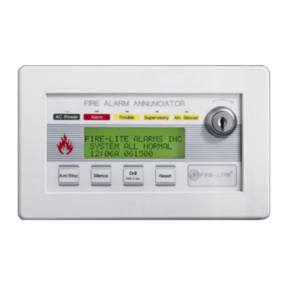
Silence Reset H o ld 2 s ec . The LCD-80F Annunciator is a compact, 80-character, backlit LCD fire annunciator designed for use with compatible FACPs (Fire Alarm Control Panel). It should be noted that the LCD-80F Annunciator display will mimic the FACP display. -
Page 7: Features Of Lcd-80F
• No programming necessary — duplicates messages at control panel display. Note: The FACP may require programming to function with the LCD-80F. Refer to the specific FACP manual for programming information • Local piezo sounder with alarm and trouble resound •... -
Page 8: Components & Wiring
Panel Configuration Top view Future use Piezo Sounder The LCD-80F sounder, if enabled, will be activated when any new alarm or trouble is Membrane Connector received from the panel. It is silenced by an Acknowledge switch. Piezo must not be... - Page 9 LCD-80F Annunciator Components & Wiring Figure 1-2: Wiring to Terminals Side view 1 2 3 4 5 6 7 8 Terminal Block replacement P/N 02109 Terminal Block 4 3 2 1 7 6 5 4 3 2 1 replacement P/N 02108...
-
Page 10: Sw1 Dip Switch Settings
Local Authority Having Jurisdiction (LAHJ). 3 -On = Supervision Receive/Transmit, Off = Supervision Receive Only. • One Annunciator - if a single LCD-80F is the only annunciator connected to the EIA-485 loop, Switch 3 must be set to the ON position to allow the FACP to supervise the annunciator. - Page 11 4 through 6 = Configuration for use with a particular FACP. Switches 4, 5 and 6 are used to select the FACP (Fire Alarm Control Panel) which is being connected to the LCD-80F. Refer to the following table for the appropriate switch settings.
- Page 12 2. DIP switch 2: Off = piezo sounder disabled (requires approval of LAHJ) 3. DIP switch 3: Off = Receive Only. This setting is used for all annunciators except the last or only LCD-80F Annunciator on the EIA-485 line 4. DIP switches 4 through 6: Off = Configured correctly for opera- tion with the available FACP 5.
-
Page 13: Typical Configuration
FACP and the first LCD-80F, between each LCD- 80F and from the last LCD-80F back to the FACP. 2. Up to 32 LCD-80F Annunciators may be used on the EIA-485 circuit. Refer to the specific FACP manual to determine the maximum current available for powering the LCD-80F. -
Page 14: Section 2: Operation
Display Patterns The LCD-80F Annunciator directly displays (mimics) the information on the FACP display with the following exceptions: • Upon Power-up, the LCD-80F may display the following message until a valid message is received from the FACP INITIALIZING... PLEASE WAIT •... -
Page 15: Switch Functions
LCD-80F. 2.2.2 Acknowledge/Step When the Acknowledge/Step switch is pressed and released, the LCD-80F sends an Acknowledge command to the control panel. Pressing the Acknowledge switch silences the local piezo sounder, the sounders located in all other system annunciators and the sounder located on the Fire Alarm Control Panel's main circuit board. -
Page 16: Silence
Acknowledge switch. In addition, if an alarm exists, it turns off all silenceable NACs and causes the FACP Alarm Silenced LED to turn on while the LCD-80F will dis- play a 'silenced' message. It also sends an 'Alarm Silenced' message to the printer and the history file within the FACP. -
Page 17: Led Indicators
The LED turns off when all trouble conditions are cleared. This LED will also illuminate if the microprocessor watch- dog circuit within the LCD-80F is activated. 2.3.5 Alarm Silenced This is a yellow LED that turns on when the Silence switch is pressed to turn off the Notification Appliance Circuits. -
Page 18: Section 3: Mounting
Never use the shield for grounding purposes. To mount the LCD-80F Annunciator in an electrical box, the trim ring must first be removed. The trim ring is held in place by two screws inserted through the top and bottom edge as illustrated in Figure 3-1. - Page 19 Supervisory Alm. Silenced Drill Ack/Step Silence Reset Hold 2 sec. LCD-80F flange LCD-80F Trim Ring (replacement P/N 23165) 3-Gang Electrical Box P/N 10103 (semi-flush mount) 3-Gang Electrical Box P/N SBB-3 (surface mount) Three Ganged Electrical Boxes Document 51338 Rev A...
-
Page 20: Semi-Flush Mount Backbox
Carefully insert the LCD-80F into the three-gang electrical box P/N: 10103 or three electrical boxes ganged together and attach it using the four mounting holes on the LCD-80F flange and the four screws pro- vided for this purpose. Replace the trim ring and secure with the two screws which were previously loosened. - Page 21 Refer to Figure 1-3 on page 12. Carefully insert the LCD-80F into the three electrical boxes ganged together and attach it using the four mounting holes on the LCD-80F flange and the four screws provided for this purpose. Replace the trim ring and secure with the two screws which were previously loosened.
-
Page 22: Surface Mount Backbox
Refer to Figure 1-3 on page 12. Carefully insert the LCD-80F into the three-gang electrical box and attach it using the four mounting holes on the LCD-80F flange and the four screws provided for this purpose. Replace the trim ring and secure with the two screws which were previously loosened. -
Page 23: Section 4: Electrical Connections
Electrical Connections Section 4: Power Connections The LCD-80F Annunciator can be powered by the FACP (refer to the specific technical manual for the proper connection of the LCD-80F) or from a remote UL listed, filtered power supply such as the FCPS-24F. -
Page 24: Eia-485 Connections
Notes: 1. All connections are power-limited and supervised 2. A maximum of 32 LCD-80F annunciators may be connected to this circuit 3. 6,000 feet (1,800 m) maximum distance @ 18 AWG (0.75 mm between the FACP and first LCD-80F, between each LCD-80F and return to the FACP from last LCD-80F 4. -
Page 25: Section 5: Eia-485 Shield Termination
, motor control circuits or SCR power circuits. Note: To ensure static (ESD - electrostatic discharge) protection, all enclosures, including the LCD-80F electrical box, must be connected to earth ground! Never use the EIA-485 shield for this purpose. The EIA-485 shield is for radiated noise emission protection (RFI, EMI). -
Page 26: Shield Not In Conduit
Shield Not in Conduit Shield Not in Conduit The EIA-485 line allows the FACP to communicate with the LCD-80F Annunciator. The shield for the EIA-485 line must be connected to earth ground at the FACP but must be left floating (no connection) at the annunciator if it is the first or only device on the EIA-485 line. -
Page 27: Shield In Full Conduit
Shield in Full Conduit Shield in Full Conduit The EIA-485 line allows the FACP to communicate with the LCD-80F Annunciator. The shield for the EIA-485 line must be connected to earth ground at the FACP (both exiting and entering the FACP) but must be left floating (no connection) at the annunciator if it is the first or only device on the EIA-485 line. - Page 28 NOTES Document 51338 Rev A 01/10/01 P/N 51338:A...
- Page 29 Index Numerics 80-character 6, 7 AC loss 7 acknowledge switch 6, 15 Acknowledge/Step switch 7 see also acknowledge switch 15 alarm LED 6, 7, 17 alarm silence switch 7 alarm silenced LED 6, 7, 16, 17 annunciator 6 annunciator, maximum 13 application see also typical configuration 13 backboxes 7, 18...
- Page 30 drill switch 6, 7, 15, 16 earth ground 18 EIA-485 6, 7, 10, 13, 20, 22, 24, 27 shield 25 EIA-485 wiring 24 electrical connections 23 enable/disable 7 see also key-switch 10 FACP compatibility 6 FACP selection 11 FCC Part 15 requirements 24 ferrite core 24 flange 20, 22 function switches 7, 10...
- Page 31 piezo sounder 7, 8, 10, 15 power for annunciator 6 power LED 6, 7, 17 power requirements 9, 13 power source 23 power-limited 9, 23 programming 7 receive only see also communication 10 receive/transmit see also communication 10 reset switch 6, 7, 15, 16 resound, piezo 7 SBB-3 backbox 18, 20 semi-flush mounting 20...
- Page 32 three ganged electrical boxes 21 trim ring 18, 19, 20, 21, 22 trouble LED 6, 7, 17 typical configuration 13 wiring 8, 9 conduit 27 distance 24 EIA-485 24 ferrite core 24 no conduit 26 power 23 type 24 wiring requirements 13 Document 51338 Rev A 01/10/01 P/N 51338:A...
- Page 33 NOTES Document 51338 Rev A 01/10/01 P/N 51338:A...
- Page 34 NOTES Document 51338 Rev A 01/10/01 P/N 51338:A...
- Page 35 Limited Warranty The manufacturer warrants its products to be free from defects in materials and workmanship for eighteen (18) months from the date of manufacture, under normal use and service. Products are date-stamped at time of manufacture. The sole and exclusive obligation of the manufacturer is to repair or replace, at its option, free of charge for parts and labor, any part which is defective in materials or workmanship under normal use and service.
- Page 36 World Headquarters One Fire-Lite Place, Northford, CT 06472-1653 USA 203-484-7161 • Fax 203-484-7118 www.firelite.com...
Need help?
Do you have a question about the LCD-80F and is the answer not in the manual?
Questions and answers