
Related Manuals for Notifier ACS Series


Summary of Contents for Notifier ACS Series
- Page 1 Annunciator Control System ACS Series Installation Manual Document 15842 7/23/2002 Rev: PN 15842:K ECN 02-266...
- Page 2 Fire Alarm System Limitations While a fire alarm system may lower insurance rates, it is not a substitute for fire insurance! An automatic fire alarm system—typically made up of Heat detectors do not sense particles of combustion smoke detectors, heat detectors, manual pull stations, and alarm only when heat on their sensors increases at audible warning devices, and a fire alarm control with a predetermined rate or reaches a predetermined level.
- Page 3 Acclimate Plus™, HARSH™, NOTI•FIRE•NET™, ONYX™, and VeriFire™ are trademarks, and FlashScan® and VIEW® are registered trademarks of NOTIFIER. NION™ and UniNet™ are trademarks of NIS. NIS™ and Notifier Integrated Systems™ are trademarks and NOTIFIER® is a registered trademark of Fire•Lite Alarms, Inc.
-
Page 4: Table Of Contents
Table of Contents Table of Contents ................... 4 1 Product Overview ..................8 General .....................8 Panel Compatibility: .................9 ACM-24AT, ACM-48A, AEM-24AT, and AEM-48A ....9 ACM-16AT, ACM-32A, Expanders, and Variations ....10 Related Documentation ................10 2 Product Overview ..................12 ACM-24AT and AEM-24AT ..............12 ACM-48A and AEM-48A ..............12 ACM-16AT Series ..................13 Control Modules ................13... - Page 5 Configuring Number of Expander Modules ........37 Speaker Control Mode ..............38 Setting Address and DIP Switches: ACM-16AT, ACM-32A ....40 DIP Switch Summary: ACM-16AT, ACM-32A ......40 Addressing ACM-16AT and ACM-32A .........40 Configuring Number of Expander Modules ........41 Supervising Devices with ACM-16AT, ACM-32A .......41 Programming the Control Panel and Annunciators ........42 Selecting LED Colors: ACM-24AT and AEM-24AT ....42 Selecting LED Colors: ACM-48A &...
- Page 6 Configuring Annunciators for the AFC-600 .......... 57 System and Point Annunciation ............. 57 Appendix E: AM2020/AFP1010 Systems ..........59 Capabilities ..................... 59 Connecting the EIA-485 Circuit ............59 Providing Power to Annunciators ............60 Programming the AM2020/AFP1010 for Remote Annunciation ..61 Configuring Annunciators for AM2020/AFP1010 ........
- Page 7 Providing Power to Annunciators ............88 Programming the NFS-3030 for Remote Annunciation ......88 Configuring Annunciators for NFS-3030 ..........89 Configurations for Specific Applications ..........90 Common System Annunciation ............90 Speaker and Telephone Mode ............91 Manual Override ................91 ACS Program Mapping .................
-
Page 8: Product Overview
Section 1.2 “Related Documentation” lists part numbers for manuals of compatible equipment such as control panels. This manual provides instructions for two sets of ACS series annunciators. Both sets can be used in the same fire alarm system. There are four basic controller modules, each with its own expander module: •... -
Page 9: Panel Compatibility
System 2500 (64 points) 1.1.2 ACM-24AT, ACM-48A, AEM-24AT, and AEM-48A These annunciators provide Notifier fire alarm control panels with up to 32 remote serially connected annunciators each with a capacity of up to 96 points (subject to the limits of your control panel), for a total maximum capacity of 3,072 points. -
Page 10: Acm-16At, Acm-32A, Expanders, And Variations
The table below provides a list of document sources (manuals) containing additional information regarding the fire alarm control panels and components that ACS annunciators can be connected to. The NOTIFIER document (DOC- NOT) chart provides the current document revision. Continued on next page... - Page 11 Product Overview Systems that support ACS modules Compatible Devices NFS-3030 Device Compatibility Document .....15378 Installation ........51330 Other ACS Devices Operation..........51344 Annunciator Fixed Module .....15048 Programming ........51345 ACM-8R Annunciator Control Module..15342 NFS-640 LCD-80 Manual........15037 Installation ........51332 LCD-80TM Manual.........51082 Operation..........51334 LDM Series Lamp Driver Annunciator ...15885 Programming ........51333 NIB-96 Network Interface Board ...15666 AFC-600...
-
Page 12: Product Overview
Product Overview Section 2 Product Overview This section is intended as a basic inventory of components that can be used in an ACS system. For system design considerations, see Section 3. For installation, configuration and programming instructions, see Section 4. For LED and Switch functions instructions, see Section 5. -
Page 13: Acm-16At Series
Product Overview 2.3 ACM-16AT Series 2.3.1 Control Modules ACM-16AT . The Annunciator Control Module- 16AT contains 16 red point active and 16 yellow trouble LEDs, 16 momentary touch-pad switches for controlling each point, a system trouble LED, an On-line/Power LED, and a local piezo sounder with a silence/acknowledge switch for audible indication of alarm and trouble conditions at each annunciator. -
Page 14: Acm-32A Series
Product Overview 24AT, ACM-48A, or ACM-32A series. Expander LED colors need not match the control module LED colors for the expander to operate. AEM-16ATY . Same as the AEM-16AT but all LEDs are yellow (yellow On/ Alarm and yellow Trouble). AEM-16ATG . -
Page 15: Cabinet & Panel Hardware
Product Overview 2.5 Cabinet & Panel Hardware 2.5.1 Surface-Mount Backboxes These backboxes provide a surface-mount enclosure for remote mounting annunciators. Knockouts are provided for use with 1/2" conduit. Dimensions are provided in Table 2-1. ABS-1B, ABS-1. Mounts one annunciator directly to the ABS-1/1B without a dress plate. -
Page 16: Semi-Flush-Mount Backboxes
Product Overview ABF-2B, ABF-2. Mounts two annunciators. ABF-2 only fits ACM-16AT/ ACM-32A series; the “B” version is black and is slightly deeper to fit either series. ABF-4B, ABF-4. Mounts four annunciators. ABF-4 only fits ACM- 16AT/ACM-32A series; the “B” version is black and is slightly deeper to fit either series. - Page 17 Product Overview Part Number Height Width Depth Color ABS-1 1.375" (3.49 cm) Gray 8.5" (21.59 cm) 4.5" (11.43 cm) ABS-1B 2.0" (5.08 cm) Black ABS-2 1.375" (3.49 cm) Gray 8.5" (21.59 cm) 8.920" (22.66 cm) ABS-2B 2.0" (5.08 cm) Black Black ABS-4D, Box: 11.97"...
-
Page 18: Additional Hardware
For use with black backboxes and dress panels. VP-2B, VP-2. Use the VP-2/2B Vented Dress Panel when annunciators are to be installed in the top row of a Notifier cabinet with the ADP-4/4B. It covers the PN 15842:K 7/23/2002... - Page 19 Product Overview gap between the ADP-4/4B and the top of the cabinet. It secures to the cabinet with two screws. The “B” version is black. AKS-1B, AKS-1. The Annunciator Key Switch provides access security for the control switches on the ACM-24AT and ACM-16AT. The key switch kit includes a key and hardware for mounting to the trim plate of a flush-mount type annunciator enclosure.
-
Page 20: Design Considerations
Section 3 Design Considerations 3.1 Limits The standard Notifier EIA-485 circuit can drive up to 32 annunciators with expanders. One system can mix ACM-24AT, ACM-48A, ACM-16AT, ACM- 32A, and their expanders with other ACS devices such as LDM, TM-4, etc. An end-of-line resistor must be installed or enabled on the last ACS device on the circuit. -
Page 21: Receive/Transmit And Receive Only Configuration
Design Considerations • The wiring size must be a 12 AWG to 18 AWG twisted shielded pair cable having a characteristic impedance of 120 ohms, +/- 20%. • Limit the total wire resistance to 100 ohms on the EIA-485 circuit, and 10 ohms on the annunciator power circuit. -
Page 22: Cabinet Mounting Of Annunciators
Design Considerations Fire Alarm Annunciator Expander Control Panel Two-wire EIA-485 Circuit “Receive only” Annunciator set to address “X” and installed upstream. Full Function “Receive/Transmit” Annunciator set to Address “X” Annunciator Expander Figure 3-1 Supervising Receive Only Annunciators 3.5 Cabinet Mounting of Annunciators ACS modules must be mounted in special backboxes or in the following cabinets using a hinged dress panel such as ADP-4/4B or DP-DISP: •... -
Page 23: Annunciator Power Requirements & Electrical Ratings
Design Considerations Annunciators in a backbox, powered from control panel Fire Alarm Control Panel Power Loop EIA-485 Reference EIA-485 Circuit Two-wire A common reference connection must EIA-485 be made between multiple power Circuit supplies for the EIA-485 circuit to function properly! Annunciators in a cabinet, powered from remote supply Figure 3-2 Using Multiple Power Supplies With the EIA-485 Circuit... - Page 24 Design Considerations Non-Fire Alarm Status A: On-line LED is flashing; all other LEDs are off Number of ACM-24AT/ACM-48A modules [_____] X 0.016 = [__________] amps Number of AEM-24AT/AEM-48A modules [_____] X 0.002 = [__________] amps Number of ACM-16AT/ACM-32A modules [_____] X 0.040 = [__________] amps Note: The 0.040 amps can be reduced to 0.030 for ACM-16AT/ACM-32A modules...
-
Page 25: Installation, Configuration, And Programming
Installation, Configuration, and Programming Section 4 Installation, Configuration, and Programming This section provides an overview of installation procedures for ACS annunciators. For wiring & programming details that are unique to a specific fire alarm control panel, refer to that panel's appendix in this manual, and to that panel's programming guide (see Section 1.2 “Related Documentation”... -
Page 26: Connections And Switches
Installation, Configuration, and Programming 4.2 Connections and Switches Addressing Configuration Expander Switches DIP Switches Connectors: SW27 SW26 Keylock J2 SW32 SW28 J3 J1 J4 J2 ACM-24ATPCA Rev. ____ AEM-24ATPCA Rev. ____ KE YLOCK Expander Connectors: PWR SUPPLY Power Supply Connectors TB2 EIA-485 EIA485 INTFC Connectors TB1... - Page 27 Installation, Configuration, and Programming Addressing Switches Configuration DIP Switches Annunciator Key Switch Connector EIA-485 Expander Connectors TB2 Connector J1 Power Supply Connectors TB1 Figure 4-3 Reverse View: ACM-16AT, ACM-32A and expanders Annunciator Key Switch Connector Tens Ones DIP Switches Annunciator Address Dip Switch set to Dip Switch set to “OFF”...
-
Page 28: Mount The Cabinet Or Backbox
Installation, Configuration, and Programming 4.3 Mount the Cabinet or Backbox Select an appropriate knockout on the enclosure for your wiring to run through and snap it out. Fasten the cabinet or backbox to the wall. Ground the enclosure to a solid metallic ground, such as a grounded cold water pipe. - Page 29 Installation, Configuration, and Programming Plug the two annunciator terminal blocks into the annunciator to complete communication and power circuit connections as described in Section 4.5 and Section 4.9. If using an annunciator backbox, place the annunciator/dress-plate assembly into the backbox and secure with two screws.
-
Page 30: Circuit Connections
Installation, Configuration, and Programming 4.5 EIA-485 Circuit Connections The accompanying figures provide EIA-485 circuit diagrams for the two different types of annunciators. Note: See Section 3.3 “EIA-485 Wiring Specifications” for circuit requirements. + IN + OUT - OUT - IN Ref Out Ref In EGnd... -
Page 31: Shielding The Eia-485 Circuit
For ACM-16AT or ACM-32A, Figure 4-12 SW29 on install a 120-ohm End-of-Line ACM-24AT or ACM-48A Resistor (Notifier Part Number 71244, supplied with the annunciator) must be installed at the last annunciator on the EIA-485 circuit (see Figure 4-10 on page 30). -
Page 32: Earth Ground
Installation, Configuration, and Programming 4.8 Earth Ground Connect Earth Ground to a mounting screw on the backbox or cabinet During mounting (see Section 4.3), the backbox or cabinet should have been connected to a solid earth ground such as a cold water pipe. •... - Page 33 Installation, Configuration, and Programming Jumper for TB2 PWR SUPPLY supervisory N.C. Trouble Inputs +24 VDC In devices (see N.C. Trouble Inputs +24 VDC Out Section 4.14) Common In Reference Out Common Out Reference In Power In Power Out Earth Ground TB2 PWR SUPPLY +24 VDC In +24 VDC Out...
-
Page 34: Labeling Annunciators & Expanders
Labels should be slightly narrower than the protector sheet to allow easier insertion. Figure 4-15 Notifier’s Magni•Fire CD contains LabelEase—a Slide-in Labels program for customizing professional slide-in labels. Apply adhesive label onto flush-mount dress plate... -
Page 35: Connecting Annunciator Key Switch And Phone Jack
Installation, Configuration, and Programming 4.11 Connecting Annunciator Key Switch and Phone Jack After applying the ABF-1, Back View appropriate label, mount with Both Options Wired key switch and/or phone Keylock jack to the dress plate. Connector Plug the switch leads (see Table 4-1) from the Annunciator Key Switch into the... -
Page 36: Setting Address And Dip Switches: Acm-24At, Acm-48A
Installation, Configuration, and Programming 4.12 Setting Address and DIP Switches: ACM-24AT, ACM-48A Annunciator switch settings will vary according to the requirements of your control panel (see this manual’s appendix section). 4.12.1 DIP Switch Summary: ACM-24AT, ACM-48A To locate these switches on the back of the annunciator, refer to Figure 4-1 and Figure 4-2. -
Page 37: Addressing Acm-24At And Acm-48A
Installation, Configuration, and Programming 4.12.2 Addressing ACM-24AT and ACM-48A Set the address with rotary SW27 Tens SW26 Ones switches SW27 and SW26 on the back of the annunciator. Turn the arrow with a small flat-head until KE YLOCK it points to the correct digit. You can connect up to 32 devices (such as ACMs, LDMs, and Figure 4-18 Rotary Switches... -
Page 38: Speaker Control Mode
Installation, Configuration, and Programming 4.12.4 Speaker Control Mode ACM-24AT boards provide a Speaker Control Mode for use with XPIQ or control modules. This is available for the following panels: AFP-300/AFP-400, AFC-600, NFS-640, NFS-3030, NCA, and AM2020/AFP1010. Note: The XPIQ can only support up to four channels. The board switches are grouped depending on the number of channels, so that the number of switches per group equals the number of channels enabled on the XPIQ. - Page 39 Installation, Configuration, and Programming 1 Switch per Group* 6 Switches per Group* Settings: SW 32-4 off, SW32-3 off, SW32-2 off Settings: SW 32-4 on, SW 32-3 off, SW 32-2 on Resulting Annunciator Point Mapping: Resulting Annunciator Point Mapping: Single-point annunciation 5-channel, 4 speakers Spkr Spkr...
-
Page 40: Setting Address And Dip Switches: Acm-16At, Acm-32A
Installation, Configuration, and Programming 4.13 Setting Address and DIP Switches: ACM-16AT, ACM-32A Annunciator switch settings will vary according to the requirements of your control panel (see this manual’s appendix section). 4.13.1 DIP Switch Summary: ACM-16AT, ACM-32A Switch Function Manual override of control relays (not supported by all control panels;... -
Page 41: Configuring Number Of Expander Modules
Installation, Configuration, and Programming 4.13.3 Configuring Number of Expander Modules Indicate the number of expanders connected to each ACM-16AT/ACM-32A by setting the DIP switch on the end of the annunciator, as shown in Table 4-4. Note: Switch locations are illustrated in Figure 4-4. To set a DIP switch “ON”, push it towards the green circuit board. -
Page 42: Programming The Control Panel And Annunciators
Installation, Configuration, and Programming 4.15 Programming the Control Panel and Annunciators After annunciator installation is complete, program the fire alarm control panel to accept the annunciators as explained in the panel's programming guide (see Section 1.2 “Related Documentation” for part numbers). 4.15.1 Selecting LED Colors: ACM-24AT and AEM-24AT Steps to set color of a point-active LED: 1. -
Page 43: Led And Keypad-Switch Functions
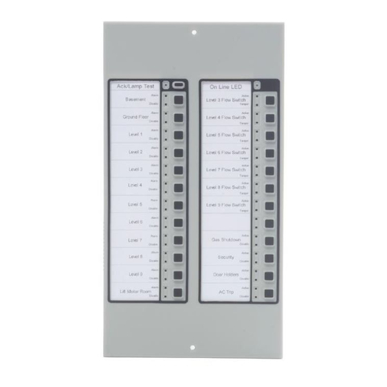
LED and Keypad-Switch Functions Section 5 LED and Keypad-Switch Functions 5.1 ACM-24AT, ACM-48A, and Expanders On-line LED Acknowledge/ Lamp Test Switch Point-Active LED System Trouble Trouble LED ACM-24AT, AEM-24AT Annunciator Points Point-Active LED ACM-48A, AEM- 48A Annunciator Points Figure 5-1 LED and Keypad-Switch Locations 5.1.1 Acknowledge/Lamp Test Switch This switch’s functions vary between ACM-24AT and AEM-24AT: •... -
Page 44: System Trouble Led
LED and Keypad-Switch Functions 5.1.3 System Trouble LED Glows yellow for all trouble conditions in the system, including points or zones not mapped to the annunciator/expanders. Flashes if communication with control panel is broken. Note: In systems capable of manual override, this LED may be used to indicate manual override mode. -
Page 45: Acm-16At, Acm-32A, And Expanders
LED and Keypad-Switch Functions 5.2 ACM-16AT, ACM-32A, and Expanders 5.2.1 ACM-16AT Local Silence/Acknowledge Switch. Performs multiple functions: • When pressed, it first lights all the LEDs on the ACM-16AT Series control module (except the On-line LED) and then each expander. Piezo sounds for as long as the switch is held down. -
Page 46: Aem-16At
LED and Keypad-Switch Functions 5.2.2 AEM-16AT Lamp Test Switch. When pressed, it lights all the LEDs on the AEM-16AT Series expander (except the On-line LED) and sounds the piezo for as long as the switch is held down. Inactive LEDs. These two LEDs are not functional on expander modules. -
Page 47: Acm-32A
LED and Keypad-Switch Functions 5.2.3 ACM-32A Local Silence/Acknowledge Switch. Performs multiple functions: • When pressed, it first lights all the LEDs on the ACM-32A Series control module (except the On-line LED) and then each expander. Piezo sounds for as long as the switch is held down. •... -
Page 48: Aem-32A
LED and Keypad-Switch Functions 5.2.4 AEM-32A Lamp Test Switch. When pressed, it lights all the LEDs on the AEM-16AT Series expander (except the On-line LED) and sounds the piezo for as long as the switch is held down. Inactive LEDs. These two LEDs are not functional on expander modules. -
Page 49: Appendix A: Afp-100 Systems
AFP-100 Systems AFP-100 Systems APPENDIX L L.1 Capabilities The AFP-100 allows annunciators to be programmed by zone or by point. The EIA-485 interface will allow up to 32 annunciators with 64 points at an address, but two-way communications can occur with only one annunciator per address. The other devices must be configured as “Receive Only”. -
Page 50: Configuring Annunciators For Afp-100
AFP-100 Systems L.4 Configuring Annunciators for AFP-100 DIP Switch Settings Note: The switch numbers given below are for SW28 on the ACM-24AT and ACM-48A, and for the 8-pin DIP switch on the ACM-16AT and ACM-32A. Address and DIP switches must be set before the annunciator will operate properly. -
Page 51: Appendix B: Afp-200 Systems
AFP-200 Systems AFP-200 Systems APPENDIX M M.1 Capabilities ACS annunciation displays the 99 software zones of the AFP-200, plus 8 system points, for a total point count of 107. Information is transmitted using only addresses 1 and 2. Up to 32 devices can be driven by the EIA-485 communications output, using two unique addresses with 64 points at an address. -
Page 52: Configuring Annunciators For The Afp-200
AFP-200 Systems M.4 Configuring Annunciators for the AFP-200 DIP Switch Settings Note: The switch numbers given below are for SW28 on the ACM-24AT and ACM-48A, and for the 8-pin DIP switch on the ACM-16AT and ACM-32A. Address and DIP switches must be set before the annunciator will operate properly. -
Page 53: Appendix C: Afp-300/Afp-400
AFP-300/AFP-400 AFP-300/AFP-400 APPENDIX N N.1 Capabilities When installed with an AFP-300/AFP-400, ACS annunciators can be used to annunciate control panel status, addressable devices, panel modules, and software zones. The fire alarm control panel uses ACS Annunciator addresses 1 through 19 (1 through 10 when employing a UDACT). Up to 32 devices can be driven by the EIA-485 communications output, all addresses combined, with up to 64 points to an address. -
Page 54: Configuring Annunciators For The Afp-300/Afp-400
AFP-300/AFP-400 N.4 Configuring Annunciators for the AFP-300/AFP-400 DIP Switch Settings Note: The switch numbers given below are for SW28 on the ACM-24AT and ACM-48A, and for the 8-pin DIP switch on the ACM-16AT and ACM-32A. Address and DIP switches must be set before the annunciator will operate properly. -
Page 55: System And Point Annunciation
AFP-300/AFP-400 N.5 System and Point Annunciation The control panel's annunciation points are divided into nine ACS Selection Groups of 64 points. Table N-1, which follows, summarizes the ACS Selection Groups and what an annunciator displays if a group is selected. The AFP-300/AFP-400 installation manual provides a complete listing of the points within the ACS Selection Groups and instructions on programming the panel for addressable annunciators. -
Page 56: Appendix D: Afc-600 Systems
AFC-600 Systems AFC-600 Systems APPENDIX O O.1 Capabilities ACS annunciators communicate with the control panel on the ACS Mode interface (TB4 on the AFC-600’s main circuit board). The ACS Mode interface can annunciate control panel, zone, detector, module, and circuit status. The 832 panel annunciation points are divided into 13 fixed ACS Selection Groups (labeled A to M) of 64 points;... -
Page 57: Configuring Annunciators For The Afc-600
AFC-600 Systems O.4 Configuring Annunciators for the AFC-600 DIP Switch Settings Note: The switch numbers given below are for SW28 on the ACM-24AT and ACM-48A, and for the 8-pin DIP switch on the ACM-16AT and ACM-32A. Address and DIP switches must be set before the annunciator will operate properly. - Page 58 AFC-600 Systems ACS Selection Group Annunciator Display 8 Systems points + Zones 1-56 Zones 57-99, 8 F zones, 4 NAC Loop 1, Modules 1-64 Loop 2, Modules 1-64 Loop 1, Modules 65-128 Loop 2, Modules 65-128 Loop 1 - Modules 129-159, 2 unused points Loop 2 - Modules 129-159, 2 unused points Loop 1, Detectors 1-64 Loop 2, Detectors 1-64...
-
Page 59: Appendix E: Am2020/Afp1010 Systems
AM2020/AFP1010 Systems AM2020/AFP1010 Systems APPENDIX P P.1 Capabilities When installed with an AM2020/AFP1010, annunciators can be programmed to annunciate the status of addressable devices, software zones, and several system control functions: Devices • Photo, Ion, and Heat Intelligent Detectors • Monitor and Control Modules •... -
Page 60: Providing Power To Annunciators
AM2020/AFP1010 Systems Software Requirements: ACM-16AT, ACM-32A The AFP1010 is fully compatible with ACS annunciators. The AM2020 must be operating with software with the following part numbers (or greater): AM2020 Board ROM Part Number Central Processing Unit (CPU-2020) 73123 and higher or M2.7 and higher Display Interface Assembly (DIA-1) 73132 and higher or M2.7 and higher Loop Interface Board (LIB-200) -
Page 61: Programming The Am2020/Afp1010 For Remote Annunciation
AM2020/AFP1010 Systems P.4 Programming the AM2020/AFP1010 for Remote Annunciation Annunciator points must be programmed from the AM2020/AFP1010 before the annunciators will function. The AM2020/AFP1010 employ the following format for annunciator points: A(xx) P(yy) Annunciator address Annunciator Points per Module In the range of 1-32, First Second Note: Points... -
Page 62: Configuring Annunciators For Am2020/Afp1010
AM2020/AFP1010 Systems P.5 Configuring Annunciators for AM2020/AFP1010 DIP Switch Settings Note: The switch numbers given below are for SW28 on the ACM-24AT and ACM-48A, and for the 8-pin DIP switch on the ACM-16AT and ACM-32A. Address and DIP switches must be set before the annunciator will operate properly. -
Page 63: Configurations For Specific Applications
AM2020/AFP1010 Systems P.6 Configurations for Specific Applications The ACS is a vital part of voice alarm applications with the AM2020/AFP1010. An ACM-24AT or ACM-16AT allows for manual selection of speaker or telephone circuits and can provide common system annunciation of circuits and software zones. -
Page 64: Speaker And Telephone Mode
AM2020/AFP1010 Systems P.6.2 Speaker and Telephone Mode To execute audio functions, use an ACM-24AT or ACM-16AT set to address 1. This annunciator (and any expanders) must be installed adjacent to the AMG-1 and points assigned for AMG control cannot be used for common system annunciation, or for the manual control of circuits and relays. - Page 65 AM2020/AFP1010 Systems When in manual override mode, all points displayed on the ACM-24AT or ACM-16AT and all its expanders will ignore subsequent Control-by-Event (CBE) commands from the panel. Manual Override Mode can be entered by pressing the Manual Override switch on the ACM-24AT or ACM-16AT module (Use special slide-in label).
-
Page 66: Acs Program Mapping
AM2020/AFP1010 Systems P.7 ACS Program Mapping ACS points “track” or follow those system points they are programmed to annunciate; the annunciator points do not latch. Table P-1, which follows, lists how the ACS annunciates various devices and functions. ACM-24AT or ACM-16AT Module and AEM-24AT or AEM-16AT Expanders ACM-48A or ACM-32A Module &... -
Page 67: Appendix F: Nfs-640 Systems
NFS-640 Systems NFS-640 Systems APPENDIX Q Q.1 Capabilities ACS annunciators communicate with the control panel on the ACS Mode interface (TB13 on the NFS-640’s main circuit board). The ACS Mode interface can annunciate control panel, zone, detector, module, and circuit status. The 832 panel annunciation points are divided into 13 fixed ACS Selection Groups (labeled A to M) of 64 points;... -
Page 68: Providing Power To Annunciators
NFS-640 Systems Q.3 Providing Power to Annunciators NFS-640 panels have an integral 24 VDC on-board power supply. The annunciator’s power supply is connected to TB7 of the control panel as shown in the accompanying illustration. No more than 1.25A can be drawn from these power-limited TB7 on NFS-640 terminals in standby or alarm. -
Page 69: Configuring Annunciators For The Nfs-640
NFS-640 Systems Q.4 Configuring Annunciators for the NFS-640 The switch numbers given below are for SW28 on the ACM-24AT and ACM-48A, and for the 8-pin DIP switch on the ACM-16AT and ACM-32A. Address and DIP switches must be set before the annunciator will operate properly. -
Page 70: System And Point Annunciation
NFS-640 Systems Q.5 System and Point Annunciation The control panel's annunciation points are divided into 13 ACS Selection Groups of 64 points. Table O-1, which follows, summarizes the ACS Selection Groups and what an annunciator displays if a group is selected. This fire alarm control panel's Programming Manual provides a complete listing of the points within the ACS Selection Groups and instructions on programming the panel for addressable annunciators. -
Page 71: Appendix G: System 500 Systems: Acm-16At And Acm-32A Only
System 500 Systems: ACM-16AT and ACM-32A Only System 500 Systems: APPENDIX R ACM-16AT and ACM-32A Only R.1 Capabilities When installed with a System 500, ACM-16AT, ACM-32A and expanders can annunciate the status of initiating and notification circuits, relays, and several system control functions. -
Page 72: Providing Power To Annunciators
System 500 Systems: ACM-16AT and ACM-32A Only (@16 AWG) between the control panel and the furthest annunciator. • Use twisted pair cable with a characteristic impedance of approximately 120 ohms. • EIA-485 circuit rated 5.5 VDC max., 60 mA max. Note: “System Trouble”... -
Page 73: Configuring The Acs For System 500
System 500 Systems: ACM-16AT and ACM-32A Only R.4 Configuring the ACS for System 500 Note: Address and DIP switches must be set before the annunciator will operate properly. DIP Switch settings Switch ACM-16AT and ACM-32A Function Not used: This switch must be set “OFF” 2, 3 Expanders installed: Set these switches according to how many expanders are installed at the address. -
Page 74: Acs Program Mapping
System 500 Systems: ACM-16AT and ACM-32A Only R.5 ACS Program Mapping Annunciator points “track” or follow those system points they are programmed to annunciate; they do not latch. Table R-1, which follows, outlines the annunciation of various system circuits and functions. ACM-16AT &... - Page 75 System 500 Systems: ACM-16AT and ACM-32A Only panel functions will be shifted out of annunciator points 1 through 8. Those eight points will annunciate the first module. 2. These control switches are active only if all of these conditions are set: •...
-
Page 76: Appendix H: System 5000 Systems: Acm-16At And Acm-32A Only
System 5000 Systems: ACM-16AT and ACM-32A Only System 5000 Systems: ACM-16AT APPENDIX S and ACM-32A Only S.1 Capabilities When installed with a System 5000, the ACS can annunciate the status of initiating and notification circuits, relays, and several system control functions. Each annunciator LED is automatically assigned to one and only one system point. -
Page 77: Providing Power To Annunciators
System 5000 Systems: ACM-16AT and ACM-32A Only Note: “System Trouble” and “Module Failure” will also occur if the normally closed supervisory path between TB1 Terminals 6 and 7 on the annunciator is opened (or the jumper has not been installed). The EIA-485 circuit that drives the ACS must be connected to the control panel as in the accompanying illustration. -
Page 78: Installing Modules In The System
System 5000 Systems: ACM-16AT and ACM-32A Only S.4 Installing Modules in the System The ACS begins annunciation with the control panel and continues with the annunciation of circuits on the module installed directly after the control panel. To ensure full employment of ACS points, mount System modules that require annunciation in the control panel row first, then in the second row, etc. -
Page 79: Configuring The Acs For System 5000
System 5000 Systems: ACM-16AT and ACM-32A Only S.5 Configuring the ACS for System 5000 Note: Address and DIP switches must be set before the annunciator will operate properly. The annunciator can be set for addresses 1, 2, 3 or 4. (Annunciator Address “3”... -
Page 80: Acs Program Mapping
System 5000 Systems: ACM-16AT and ACM-32A Only S.6 ACS Program Mapping Annunciator points “track” or follow those system points they are programmed to annunciate; they do not latch. Table S-1 outlines the annunciation of various system circuits and functions. ACM-16AT & AEM-16AT ACM-32A &... -
Page 81: Point Annunciation
System 5000 Systems: ACM-16AT and ACM-32A Only 2. These control switches are active only if all of the following conditions are set: • Receive Only (DIP Switch #5) is set to “OFF”. • Switch Inhibit (DIP Switch #7) is set to “OFF”. 3. - Page 82 System 5000 Systems: ACM-16AT and ACM-32A Only • 48 points mapped to the next six modules installed in the System (which can also be AIM-200s for annunciation of their eight software zones). Annunciator Address 2: • Intelligent Detectors, addressed 1-64, on the AIM-200 installed next to the control panel.
-
Page 83: Appendix I: Combination Fire Alarm/Burglary Systems
Combination Fire Alarm/Burglary Systems Combination Fire Alarm/Burglary APPENDIX T Systems ACS annunciators can be used in combination fire/burglary and burglary systems within the requirements set forth in this appendix. 1. Shielded cable must be used on all input/output wiring. Terminate both ends of the shield at earth ground. -
Page 84: Appendix J: Nca Systems
NCA Systems NCA Systems APPENDIX U U.1 Capabilities ACS annunciators communicate with the control panel on the ACS Mode interface (TB3 on the NCA’s main circuit board). Annunciators can be programmed to annunciate the status of addressable devices, software zones, system control functions or shadowing ACS points mapped to an AM2020/ AFP1010. -
Page 85: Programming The Nca For Remote Annunciation
NCA Systems U.4 Programming the NCA for Remote Annunciation Annunciator points must be programmed from the NCA before the annunciators will function. The NCA employ the following format for annunciator points: A(xx) P(yy) Annunciator address Annunciator Points per Module In the range of 1-32, Second as set on the ACM-24AT,... -
Page 86: Configuring Annunciators For The Nca
NCA Systems U.5 Configuring Annunciators for the NCA The switch numbers given below are for SW28 on the ACM-24AT and ACM-48A, and for the 8-pin DIP switch on the ACM-16AT and ACM-32A. Address and DIP switches must be set before the annunciator will operate properly. -
Page 87: Appendix K: Nfs-3030 Systems
NFS-3030 Systems NFS-3030 Systems APPENDIX V V.1 Capabilities When installed with an NFS-3030, annunciators can be programmed to annunciate the status of addressable devices, general zones, logic zones, and several system control functions: Devices • Intelligent Detectors • Monitor and Control Modules •... -
Page 88: Providing Power To Annunciators
NFS-3030 Systems V.3 Providing Power to Annunciators The annunciator’s power supply is connected to TB6 on the AMPS-24/E, as shown in the accompanying illustrations. The power run to the annunciator does not require a Power Supervision Relay. Loss of power is inherently supervised through a Communications loss. -
Page 89: Configuring Annunciators For Nfs-3030
NFS-3030 Systems V.5 Configuring Annunciators for NFS-3030 DIP Switch Settings Note: The switch numbers given below are for SW28 on the ACM-24AT and ACM-48A, and for the 8-pin DIP switch on the ACM-16AT and ACM-32A. Address and DIP switches must be set before the annunciator will operate properly. -
Page 90: Configurations For Specific Applications
NFS-3030 Systems V.6 Configurations for Specific Applications The ACS is a vital part of voice alarm applications with the NFS-3030. An ACM-24AT or ACM-16AT allows for manual selection of speaker or telephone circuits and can provide common system annunciation of circuits and logic zones. -
Page 91: Speaker And Telephone Mode
NFS-3030 Systems V.6.2 Speaker and Telephone Mode To execute audio functions, use an ACM-24AT or ACM-16AT set to address 1. This annunciator (and any expanders) must be installed adjacent to the AMG-1 and points assigned for AMG control cannot be used for common system annunciation, or for the manual control of circuits and relays. - Page 92 NFS-3030 Systems When in manual override mode, all points displayed on the ACM-24AT or ACM-16AT and all its expanders will ignore subsequent Control-by-Event (CBE) commands from the panel. Manual Override Mode can be entered by pressing the Manual Override switch on the ACM-24AT or ACM-16AT module (Use special slide-in label).
-
Page 93: Acs Program Mapping
NFS-3030 Systems V.7 ACS Program Mapping ACS points “track” or follow those system points they are programmed to annunciate; the annunciator points do not latch. Table P-1, which follows, lists how the ACS annunciates various devices and functions. ACM-24AT or ACM-16AT Module and AEM-24AT or AEM-16AT Expanders ACM-48A or ACM-32A Module &... - Page 94 NFS-3030 Systems Notes PN 15842:K 7/23/2002...
-
Page 95: Index
Index Point annunciation 57 Power connections 56 ABF, ABS see Backboxes Selection groups 57 ABM-1 18 Speaker Control Mode 38 ACM-16AT 10, 26, 27, 41 AFP-100 9 Addressing 40 DIP switches 50 Color variations 13 Power connections 49 DIP switches 40, 41 AFP1010, see AM2020/AFP1010 Expanders 28, 29 AFP-200 9... - Page 96 AFC-600 57 32A only) 71 AFP-100 50 System 5000 (ACM-16AT, ACM- AFP-200 52, 54 32A only) 76 AFP-300/AFP-400 54 Eight-point shift 40 AM2020/AFP1010 62, 63 System 500 73, 74 DIP switch locations 26 System 5000 78, 79, 80 NCA 86 Electrical ratings 23 NFS-3030 89, 90 End of line resistor 31, 35...
- Page 97 multi-speakers 38 Program mapping AM2020/AFP1010 66 NFS-3030 93 System 500 74 NCA 38, 84 System 5000 80 DIP switches 86 NFS-3030 9, 10, 38, 87 Applications 90 Common system annunciation 90 Receive Only Annunciators 21, 22 DIP switches 89, 90, 92 Receive/transmit annunciators 21 Power connections 88 Related Documentation 11...
- Page 98 Trouble LEDs see LEDs UDACT ACM-16AT, ACM-32A 40 ACM-24AT, ACM-48A 37 AFC-600 56 AFP-200 40 AFP-300/AFP-400 53 NFS-640 67 System 500 75 System 5000 81 VeriFire™ 9, 10, 56 Voice applications, AM2020/ AFP1010 63 Voice applications, NFS-3030 90 VP-2, VP-2B 18 Wiring 28, 30, 33, 35 XPIQ 38 Zone mapping, AFP-300/AFP-...
- Page 99 Products are date stamped at time of manufacture. The sole and exclusive obligation of NOTIFIER® is to repair or replace, at its option, free of charge for parts and labor, any part which is defective in materials or workmanship under normal use and service.
- Page 100 World Headquarters NOTIFIER is an operation of 12 Clintonville Road Northford, CT 06472-1653 USA 203-484-7161 fax 203-484-7118 www.notifier.com...
Need help?
Do you have a question about the ACS Series and is the answer not in the manual?
Questions and answers