Table of Contents
Advertisement
INDUSTRIAL DUTY COMMERCIAL DOOR OPERATOR
INTENDED FOR PROFESSIONAL
INSTALLATION ONLY
Visit www.LiftMaster.com to locate a professional
installing dealer in your area.
2 Y E A R W A R R A N T Y
Serial # Box
Installation Date
O W N E R ' S M A N U A L
GH
A SAFETY DEVICE IS HIGHLY RECOMMENDED
L
ogic
This Operator Features
the Enhanced
PAT E N T P E N D I N G
The Maintenance Alert System™ allows the
installer to set an internal Maintenance
Cycle Counter. The Logic 3 operator
incorporates a self-diagnostic feature built
into the (MAS) Maintenance Alert System
LED. An LED on the 3-button station will
signal when the set number of cycles/
months is reached or when the operator
requires immediate service.
Radio Receiver
Built on Board
315MHz
NOT FOR RESIDENTIAL USE
3
Advertisement
Table of Contents
Troubleshooting

Related Manuals for Chamberlain door opener


Summary of Contents for Chamberlain door opener
- Page 1 INDUSTRIAL DUTY COMMERCIAL DOOR OPERATOR INTENDED FOR PROFESSIONAL INSTALLATION ONLY Visit www.LiftMaster.com to locate a professional installing dealer in your area. 2 Y E A R W A R R A N T Y Serial # Box Installation Date O W N E R ’ S M A N U A L A SAFETY DEVICE IS HIGHLY RECOMMENDED ogic This Operator Features...
-
Page 2: Table Of Contents
SPECIFICATIONS Carton Inventory ........3 Operator Dimensions . -
Page 3: Carton Inventory
Before beginning your installation check that all components were provided. DESCRIPTION POWERHEAD ASSEMBLY OWNER’S MANUAL AND CAUTION LABELS HARDWARE BOX (INCLUDES FASTENERS, DISCONNECT AND CHAIN HOIST WALL BRACKET) 3-BUTTON CONTROL STATION WITH LED HOIST HAND CHAIN DOOR SPROCKET DOOR/OPERATOR DRIVE CHAIN WEIGHTS AND DIMENSIONS HANGING WEIGHT: 80-110 LBS. -
Page 4: Operator Specifications
O P E R A T O R S P E C I F I C A T I O N S MOTOR TYPE: ....... .Continuous Duty HORSEPOWER: . -
Page 5: Preparation
WARNING It is imperative that the wall or mounting surface provide CAUTION adequate support for the operator. This surface must: a. Be rigid to prevent play between operator and door shaft. b. Provide a level base. c. Permit the operator to be fastened securely and with the drive shaft parallel to the door shaft. -
Page 6: Installation
IMPORTANT NOTE: Before your operator is installed, be sure the door has been properly aligned and is working smoothly. The operator may be wall mounted or mounted on a bracket or shelf. If necessary, refer to the preparation on page 5. Refer to the illustrations and instructions below that suit your application. -
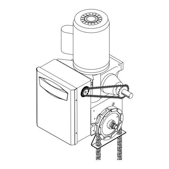
Page 7: Manual Operation
MANUAL OPERATION This operator has provisions for manually operating the door in case of emergency or power failure. These operators are equipped with a manual hoist. An electrical interlock will disable the electrical controls when the hoist is used. To operate the hoist: 1. -
Page 8: Entrapment Protection Accessories
ENTRAPMENT PROTECTION ACCESSORIES (OPTIONAL) PHOTO EYES AND SENSING EDGES Sensing devices provided for door industry type operators with an isolated normally open (N.O.) dry contact output are compatible with your operator. This includes pneumatic and electric edges, and through beam and retro reflective photo eyes. If you would like to order or receive more information on safety devices, please contact your local Authorized Dealer. -
Page 9: Adjust Torque Limiter Clutch
ADJUST TORQUE LIMITER CLUTCH (OPTIONAL MODIFICATION) 1. Loosen set screws on clutch nut. 2. Back off clutch nut until there is very little tension on the clutch spring. 3. Tighten clutch nut gradually until there is just enough tension to permit the operator to move the door smoothly but to allow the clutch to slip if the door is obstructed. -
Page 10: Safety Warnings
P O W E R W I R I N G & G R O U N D W I R I N G To reduce the risk of SEVERE INJURY or DEATH: • ANY maintenance to the operator or in the area near the operator MUST NOT be performed until disconnecting the electrical power and locking-out the power via the operator power switch. -
Page 11: Control Station Wiring & Installation
C O N T R O L S T A T I O N W I R I N G A N D I N S T A L L A T I O N CONTROL WIRING CONNECTIONS 1. Connect control wires to the P1 terminal block located on the logic board as shown. -
Page 12: Standard Power & Control Connection Diagrams
S T A N D A R D P O W E R & C O N T R O L C O N N E C T I O N D I A G R A M S Radio Control (24V DC only) CPS-L &... -
Page 13: Phase Wiring Diagram
L O G I C ( V E R . 3 . 0 ) 1 P H A S E W I R I N G D I A G R A M 115V MOTOR CONNECTION 230V MOTOR CONNECTION NOTE: Gray (GY) and purple (PU) motor wires are reversed for H and HJ right hand models and all GH and J models. -
Page 14: L O G I C ( V E R . 3 . 0 ) 3 P H A S E W I R I N G D I A G R A M
L O G I C ( V E R . 3 . 0 ) 3 P H A S E W I R I N G D I A G R A M (GY) (BR) (PU) (BR) (YE) 208/230V MOTOR CONNECTION 460V MOTOR CONNECTION NOTE: Gray (GY) and purple (PU) motor wires are reversed for H and HJ right hand... -
Page 15: Logic Board
Auxiliary Board Connections Programmed Chip Maximum Run Timer Button Radio Learn Button Mid Stop Learn Button Timer to Close Learn Button L O G I C B O A R D Ø14LGØ657–A Ø14GPØ657–A D3Ø2 J3ØØ TIMER TIMER RADIO ENABLE RELAY A RELAY B FAILSAFE ( B2 C2 D1 E2 ) -
Page 16: Programming
LOGIC CONTROL PUSHBUTTONS OPEN, CLOSE, STOP Open, Close and Stop buttons are mounted directly on the logic board. Thus, making it easy to program as well as have door control at the electrical box. Either the stop control or a jumper must be wired between terminals 4 and 5 for the on board push buttons to function. -
Page 17: Failsafe Wiring Types
FAILSAFE WIRING TYPES TYPE Momentary contact to open, close, and stop with open override and Timer To Close. Every device that causes door to open, including a reversing device, activates the Timer To Close. Auxiliary controls can be connected to open input to activate the Timer To Close. -
Page 18: Programming Remote Controls
STANDARD SINGLE BUTTON REMOTE CONTROL Built in 3-channel, 315MHz radio receiver allows you to add as ® many as 23 Security✚ remote controls or dip switch remote controls. PROGRAMMING REMOTE CONTROLS STANDARD SINGLE BUTTON REMOTE CONTROL 1. To enter programming, press and release the RADIO button on the logic board (LED will light). - Page 19 3-BUTTON REMOTE CONTROLS Your 315MHz Security✚ ® or dip switch remote control can be programmed to operate as a 3-button wireless control station: the large button will open the door, the middle button will close the door, and the third button will stop the door’s movement.
-
Page 20: Maintenance Alert System (Mas)
MAINTENANCE ALERT SYSTEM (MAS) Feature: An internal cycle counter will activate a flashing LED on the 3-button control station when the preset number of cycles or months has elapsed (whichever occurs first). Setting this feature is optional. By default this feature will never activate. Logic 3.0 operators incorporate a self diagnostic feature built into the MAS LED. -
Page 21: Mid Stop
OPEN MID STOP Feature: The mid stop feature is to open the door to a preset point prior to the fully open position. Benefit: The door opens to a midpoint between open and close reducing heating and cooling costs. The door will not cycle fully, providing longer door and operator life. -
Page 22: Car Dealer Mode
TIMER TO CLOSE PROGRAM TIMER TO CLOSE BY EXAMPLE (Method 2): To Program: 1. Close the door. 2. Turn the selector dial to PROGRAM. 3. Press and hold TIMER button for 5 seconds until TIMER LED flashes. 4. Press the OPEN button and wait for the door to reach full open or mid stop position. -
Page 23: Automatically Learned Programming
A U T O M A T I C A L L Y L E A R N E D P R O G R A M M I N G AUXILIARY REVERSAL SYSTEM / RPM SENSOR Feature: This feature utilizes the RPM sensor connected to the logic board to detect when the clutch slips and reverses the door (clutch must be properly adjusted). -
Page 24: Optional Programming
RED/GREEN WARNING LIGHT CARD Feature: The Red/Green warning light card flashes a warning light for 10 seconds prior to the Timer to Close activating the door to close. Benefit: Advanced warning of the door closing helps prevent traffic collisions with the door. Light Control Module Operation: The green lights on the OPTION BOARD will turn on if the board is seated properly and the power is on. -
Page 25: Maintenance
MAINTENANCE SCHEDULE For use with Maintenance Alert System. Check at the intervals listed in the following chart: ITEM PROCEDURE Drive Chain Check for excessive slack. Check and adjust as required. Lubricate. Sprockets Check set screw tightness. Clutch Check and adjust as required. Belt Check condition and tension. -
Page 26: Troubleshooting
DIAGNOSTIC CHART The logic board has several LEDs to assist in the installation and troubleshooting of the operator. The following chart should assist in verifying the operator is functioning properly. Turn the selector dial to DIAGNOSTIC to keep the door from moving while troubleshooting. -
Page 27: Troubleshooting Guide
TROUBLESHOOTING GUIDE FAULT POSSIBLE CAUSE THE OPERATOR WILL a) No power supply NOT RESPOND TO ANY b) Operator control station is wired wrong COMMANDS c) Interlock switch is activated d) Dial still in programming or diagnostic mode e) Motor is malfunctioning f) Motor thermal overload tripped g) Failsafe switch is activated requiring photo eyes... -
Page 28: Troubleshooting Error Codes
TROUBLESHOOTING ERROR CODES Logic 3.0 operators incorporate a self diagnostic feature built into the MAS LED. In addition to indicating when routing maintenance is due, the MAS LED can be used to troubleshoot some problems with the operator. If the MAS LED is flashing on and off rapidly, the Maintenance Alert System has been triggered and the schedule operator service is due. -
Page 29: Troubleshooting Radio Functionality
TROUBLESHOOTING RADIO FUNCTIONALITY The error codes will display at the radio LED. NOTE: Radio receiver is compatible with 315 MHz remotes. ERROR CODE SYMPTOM No response from the remote. No response from the remote. The remote cannot be learned. The remote cannot be learned. -
Page 30: Electrical Box
E L E C T R I C A L B O X (K72-12515-1) (K72-10047) (K72-10047-1) - Page 31 E L E C T R I C A L B O X L O G I C ( V E R 3 . 0 ) For replacement of electrical box, motor or brake components be sure to match model number of your unit to kit number below to ensure proper voltage requirements.
-
Page 32: M O D E L G H
M O D E L G H K5 (K75-12829) (K75-12830) (K75-12831) (K75-12832) (K75-12833) K2 (K75-10177) K1 (K75-12584) (K75-12585) (K75-12586) K4 (K75-30737) K3 (K72-12789) - Page 33 R E P A I R P A R T S K I T S - M O D E L G H SERVICE KITS ITEM PART # DESCRIPTION K75-12584 Brake kit - 115 Volt models K75-12585 Brake kit - 230-460 Volt models K75-12586 Brake kit - 575 Volt models Complete with: Brake hub kit, brake release lever, brake disc, spring cup,...
-
Page 34: Operator Notes
O P E R A T O R N O T E S... -
Page 35: Operator Notes
O P E R A T O R N O T E S... -
Page 36: Control Connection Diagram
Alert LED Stop (WHITE) D1 & E2 MODE ONLY See note 2. B2, T, TS & FSTS MODE ONLY See note 2. ©2009, The Chamberlain Group, Inc. All Rights Reserved KEY LOCKOUT (RED) Open Open Maintenance Alert LED Close Close...
Need help?
Do you have a question about the door opener and is the answer not in the manual?
Questions and answers