
Related Manuals for ETIC IPL-E-2 Series


Summary of Contents for ETIC IPL-E-2 Series
- Page 1 Router - Firewall _________________ USER GUIDE _________________ DOC_DEV_IPL_User guide_D...
- Page 2 The IPL Industrial Router family is manufactured by ETIC TELECOM 13 Chemin du vieux chêne 38240 MEYLAN FRANCE TEL : + (33) (0)4-76-04-20-05 E-mail : hotline@etictelecom.com web : www.etictelecom.com Page 2 DOC_DEV_IPL_User guide_D...
- Page 3 UE DECLARATION OF CONFORMITY The manufacturer, ETIC Telecom – 13 chemin du vieux chêne – 38240 Meylan – France, Hereby declares under sole responsibility that the listed devices conform to the Radio Equipment Directive (RED) 2014/53/UE, the Restriction of the use of certain Hazardous Substances (RoHS) Directive 2011/65/UE.
- Page 4 Caution: ETIC Telecom has not approved any changes or modifications to this device by the user. Any changes or modifications could void the user's authority to operate the equipment.
-
Page 5: Table Of Contents
TABLE OF CONTENTS OVERVIEW ............................. 7 Purpose of this manual ............................ 7 Products Identification ............................. 7 Specifications..............................9 Product overview ............................12 Applications ............................12 IPL functions ............................14 INSTALLATION ........................... 17 Description ..............................17 Dimensions ............................17 Connectors ............................18 Push-buttons ............................ - Page 6 TABLE DES MATIERES Page 6 DOC_DEV_IPL_User guide_D...
-
Page 7: Overview
OVERVIEW OVERVIEW Purpose of this manual The present user guide describes the features and the installation of the IPL Industrial Router family. In the rest of the document the term "SIG" is used to designate the product. Products Identification This family of Industrial Router consists of these models: IPL-C-100, IPL-E-100, IPL-EW-100 IPL-E-400, IPL-E-2XX, IPL-EW-400, IPL-EW-2XX, IPL-A-400, IPL-A-2XX, IPL-AW-400, IPL-AW-2XX,... - Page 8 OVERVIEW Models with serial interface code: RS232 RS485 RS422 RS485 isolated isolated In the remainder of this document the term IPL-X is used indifferently for IPL-C, IPL-E, IPL-EW, IPL-A, IPL-AW and IPL-CW. Page 8 DOC_DEV_IPL_User guide_D...
-
Page 9: Specifications
OVERVIEW Specifications General characteristics IPL-X-100: 120 x 37 x 88 mm (h,w,d) Dimensions Other IPL: 135 x 47 x 115 mm (h,w,d) Max 0.65 kg Weight Metallic Casing IPL- X-100: IP41 – IEC60529 Other IPL: IP20 – IEC60529 DIN rail mounting Non-operating: -40°/ + 85°C Temperature Operating: -20°/ +70°C... - Page 10 Address translation (DNAT, SNAT, NAT 1:1) IP@ assignment WAN interface: DHCP client or fixed IP LAN interface: DHCP server WAN interface: compatible with DYNDNS, No-IP or ETIC DNS LAN interface: relay & server VRRP RFC 3768 protocol Redundancy Multi WAN for backup on some IPL models...
- Page 11 RS485 : 2 points Phoenix connector 1 port USB host PPP client Misc. SNMP Supported MIBs: RFC1213-MIB (MIB-2) ADSL-LINE-MIB ETIC-TELECOM-MIB-1 SNMP traps Web server Configuration Save and restore configurations Management Reset product to return to factory configuration Page 11 DOC_DEV_IPL_User guide_D...
-
Page 12: Product Overview
OVERVIEW Product overview The IPL is both a router, a firewall and a remote access server. It is designed to connect industrial machines on an intranet or the Internet with a high level of security. It provides depending on model : IPL-E : A WAN Ethernet interface IPL-A : An ADSL modem IPL-C : A 3G/4G cellular modem... - Page 13 OVERVIEW High availability SCADA system with an IPL-DAC. Remote access server for remote operation A remote user can connect to any device in the system using a PC, tablet or a smartphone. His access rights may be limited according to his identity.
-
Page 14: Ipl Functions
OVERVIEW IPL functions IP router The IPL provides powerful, flexible and comprehensive solutions to route IP packets from one network to other networks: Static routes, to reach nested networks, Network address translation d‘adresse (NAT, DNAT, port forwarding), Routing protocol (RIP), Domain name management DNS et DynDNS. - Page 15 Configuration The IPL is configured using an HTML browser (HTTP or HTTPS). EticFinder The ETICFinder software can easily detect all ETIC branded products connected to an Ethernet network to display their MAC address and their IP address. Serial gateway Optionally, the IPL provides 1 or 2 serial RS232, RS485, RS422 interfaces.
-
Page 17: Installation
INSTALLATION INSTALLATION Description Dimensions All models except IPL-X-100 IPL-X-100 88 mm 35 mm Din rail axis Page 17 DOC_DEV_IPL_User guide_D... -
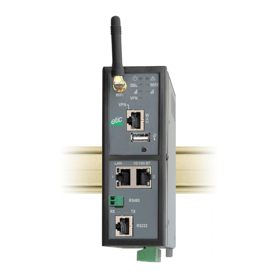
Page 18: Connectors
INSTALLATION Connectors IPL-E-400 IPL-EW-400 IPL-A-400 IPL-AW-400 Page 18 DOC_DEV_IPL_User guide_D... - Page 19 INSTALLATION IPL-C-400 IPL-CW-400 Page 19 DOC_DEV_IPL_User guide_D...
- Page 20 INSTALLATION IPL-DEC-400 IPL-DAC-400 Cellulaire ant. Ethernet WAN Push button B1 Auxiliary ant. Ethernet Reset push button on the rear pannel 4 pos. screw block 1 digital input 1 digital output Ground terminal Double 2 pos. Screw block Sup. voltage IPL-DAE-400 Page 20 DOC_DEV_IPL_User guide_D...
- Page 21 INSTALLATION Serial interfaces IPL-X-220 IPL-X-230 Ethernet Ethernet RS485 (2 wires) RS232 RS232 RS232 IPL-X-260 IPL-X-261 Ethernet Ethernet RS485 isolated RS422 isolated (3 wires) (4 wires) DIP switches DIP switches Page 21 DOC_DEV_IPL_User guide_D...
- Page 22 INSTALLATION IPL-E-100 IPL-EW-100 Wi-Fi Ethernet WAN Ethernet WAN Push button B1 Push button B1 Ethernet LAN Ethernet LAN 2 pos. screw pos. screw block Power block Power Reset push supply Reset push supply button on the button on the rear rear pannel pannel Ground...
- Page 23 INSTALLATION All models except IPL-X-100 Ground terminal Description Symbol FASTON male lug 6.35 mm Ground terminal Description Symbol M4 screw terminal All models except IPL-X-100 2 positions screw terminal: Supply voltage 1 Position 1 at back – Protected against reverse polarity Position Signal Function...
- Page 24 INSTALLATION Ethernet RJ45 connector Position Signal Function RJ45 Tx + Emission polarity + Tx - Emission polarity - Rx + Reception polarity + Rx - Reception polarity - N.C. N.C. Antenna connectors Antenna Network Type Observation Cellular SMA female 3G et 4G Cellular SMA female To improve the 4G transmission data rate, 2 antennas can be...
- Page 25 INSTALLATION IPL-X-260 5 positions screw terminal : RS422 isolated Position Signal Function Emission polarity + Emission polarity - Common isolated Reception polarity + Reception polarity - IPL-X-220 et IPL-X-230 RJ45 connector : RS232 To connect a DCE Position Signal Direction Function RJ45 DTR - 108...
-
Page 26: Push-Buttons
The current configuration is deleted except if it has been saved into a file. Front panel push-button Pressing the PB Function 10 seconds 5 flashes The hotline of ETIC TELECOM is authorized to connect remotely to the router administration server within a 1 hour delay. Page 26 DOC_DEV_IPL_User guide_D... -
Page 27: Led Indicators
INSTALLATION LED indicators LED indicators Depending on models Function Description Operation Power off Steady green The unit is ready Slow blinking green The unit is busy Steady red Startup (30s) – Hardware or software failure or SIM card missing or memory flash drive missing Fast blinking red Firmware download in progress Application... -
Page 28: Safety Instructions
INSTALLATION Safety instructions The product shall be installed in a fire electrical resistant cabinet by a qualified operator. The product shall be connected only to equipment that complies with the IEC60950-1 or IEC62368-1 standards and that meets the following classifications: IEC60950-1 : Limited power circuits and SELV type –... -
Page 29: Din Rail Mounting
INSTALLATION DIN rail mounting Mounting the unit on the 35 mm horizontal DIN rail Removing the unit from the DIN rail Cooling The product is designed to be mounted on a 35mm DIN rail. To avoid obstructing the airflow around the unit, the spacing must be at least 25 mm above and below, and 10 mm left and right. -
Page 30: Power Supply
INSTALLATION Power supply All models except IPL-X-100 : These products provide a dual power inputs allowing a redundancy power supply. The supply voltage must be regulated and strictly between 10 and 60 Volt DC (nominal: 12 – 48 VDC). At power up the inrush current can reach 20 A for 100 µs. IPL-X-100 : These products provide a single power input. -
Page 31: Rs422 Isolated Serial Connection (Ipl-X-260)
INSTALLATION RS422 isolated serial connection (IPL-X-260) The polarization and termination resistors can be selected with DIP switches. The termination resistor must be enabled when the product is located at the extremity of the RS422 bus. The polarization resistors must be enabled by one device of the bus. -
Page 32: Rs485 Isolated Serial Connection (Ipl-X-261)
INSTALLATION RS485 isolated serial connection (IPL-X-261) The polarization and termination resistors can be selected with DIP switches. The termination resistor must be enabled when the product is located at the extremity of the RS485 bus. The polarization resistors must be enabled by one device of the bus. -
Page 33: Digital Input And Output
INSTALLATION Digital input and output To check that the input and the output are IPL router correctly wired : Digital output Digital input In the menu, select isolated Non isolated Diagnostics > Hardware > Input/Output polarized The status of the input is displayed and the output can be switched ON or OFF. -
Page 34: Connecting To The Adsl Line
INSTALLATION Connecting to the ADSL line Line length / signal level : The IPL-A can be connected to an analogue line telephone line or an unbundled loop when the attenuation of the reception signal is better than 63 dB When the reception level is close to the limit, disconnections may occur. In that situation, we recommend to ask to the ISP to setup the line with the RE-ADSL modulation which is suited for long line and weak signal. -
Page 35: Connecting To The Cellular Network
INSTALLATION Connecting to the cellular network 13.1 Pre-installation checks Authorization to use a cellular connection Check the cellular connection is authorized at the location where the IPL is supposed to be installed. Control of the reception level before installing the machine Before installing the IPL, refer to a cell map over the Internet to check that the cellular reception signal is strong enough at the location where the machine is supposed to be installed. -
Page 36: Cellular Service Subscription
INSTALLATION 13.4 Cellular service subscription The IPL is designed to connect to the LTE-UMTS-GPRS data transmission service like the one used by the tablets. The subscription should also provide the SMS service if SMS alarms are required. A telephone service subscription is not needed. One will take care to subscribe to a service authorizing the right volume of data per month (MB/month) and to check the price of the MB exceeding the limit of the subscription plan, if it exists. -
Page 37: Installing Or Removing The Sim Card
INSTALLATION 13.5 Installing or removing the SIM card All cellular IPL models except IPL-C-100, These models provide two SIM card holders. If you use only one SIM card, use the SIM card holder Nr 1 (at left on the pictures). Installing the SIM card: Power off the IPL. -
Page 38: Controlling The Conformance Of The Connection
INSTALLATION 13.6 Controlling the conformance of the connection After installing and setting up the IPL, control the conformance of the connection: Reception level The reception level must be better than -90 dBm (two flashes of the reception level led indicator). See the table below. -
Page 39: Preparing The Setup
PREPARING THE SETUP PREPARING THE SETUP Connecting a PC for configuration Overview The IPL is configured using a PC with a web browser. No additional software is required. Online help: For most pages of the administration server an help page is available by clicking located at the top right of the page. -
Page 40: First Configuration
PREPARING THE SETUP First configuration Step 1: Create or modify the PC TCP/IP connection Assign to the PC an IP address different but consistent with the factory IP address of the IPL. For the first configuration, assign for instance 192.168.0.1 to the PC. Step 2: Connect the PC to the IPL Connect the PC directly to the IPL with any Ethernet cable (straight or cross-wired);... -
Page 41: Access To The Administration Server Through The Wan Interface
PREPARING THE SETUP Access to the administration server through the WAN interface To allow the access to the administration server through the WAN interface: • In the menu, choose Setup > Security > Administration rights. • Enter the username and the password. •... -
Page 42: Temporary Return To The Factory Settings
EticFinder can be used. This software detects all ETIC branded products on a local network. After starting the software, click on the "Search" button, and when the product list is displayed, double-click on the product address to access the html server. -
Page 43: Protecting The Access To The Administration Server
PREPARING THE SETUP Protecting the access to the administration server • In the menu, choose Setup > Security > Administration rights • Enter a user name and password to protect the administration server. • Tick the Password protect the web site access checkbox If the username and password to access the administration server are lost, you have to temporarily return to... - Page 44 13, Chemin du Vieux Chêne 38240 Meylan - France Tel : +33 (0)4 76 04 20 00 contact@etictelecom.com www.etictelecom.com...
Need help?
Do you have a question about the IPL-E-2 Series and is the answer not in the manual?
Questions and answers