Table of Contents
Advertisement
Quick Links
OPERATOR'S MANUAL
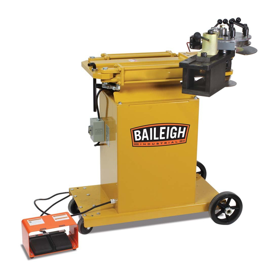
ROTARY DRAW BENDER
MODEL: RDB-150 & RDB-150-AS
Baileigh Industrial Holdings LLC
P.O. Box 531
Manitowoc, WI 54221-0531
Phone: 920.684.4990
Fax: 920.684.3944
sales@baileigh.com
REPRODUCTION OF THIS MANUAL IN ANY FORM WITHOUT WRITTEN APPROVAL OF BAILEIGH INDUSTRIAL
HOLDINGS LLC IS PROHIBITED. Baileigh Industrial Holdings LLC, Inc. does not assume and hereby disclaims any
liability for any damage or loss caused by an omission or error in this Operator's Manual, resulting from accident,
negligence, or other occurrence.
Rev. 05/2019
© 2019 Baileigh Industrial Holdings LLC
Advertisement
Table of Contents

Related Manuals for Baileigh Industrial RDB-150-AS


Summary of Contents for Baileigh Industrial RDB-150-AS
- Page 1 REPRODUCTION OF THIS MANUAL IN ANY FORM WITHOUT WRITTEN APPROVAL OF BAILEIGH INDUSTRIAL HOLDINGS LLC IS PROHIBITED. Baileigh Industrial Holdings LLC, Inc. does not assume and hereby disclaims any liability for any damage or loss caused by an omission or error in this Operator’s Manual, resulting from accident, negligence, or other occurrence.
-
Page 2: Table Of Contents
Square Tooling Setup ....................32 Large Size Square ..................... 33 LUBRICATION AND MAINTENANCE ................34 RDB-150 ELECTRICAL SCHEMATIC ................35 RDB-150-AS ELECTRICAL SCHEMATIC ..............36 HYDRAULIC DIAGRAM ....................37 TROUBLESHOOTING ....................38 TABLES, CHARTS, & DIAGRAMS ................40 Diagram 1 ........................43 Diagram2 ........................ - Page 3 Power Unit and Cart Assembly Parts Diagram ............45 Main Tube and Cylinders Assembly Parts Diagram ..........46 Swing Arm Assembly Parts Diagram ................. 47 Degree Dials Parts Diagram ..................48 Parts List ........................49 Main Tube Assembly Parts Diagram ................. 51 Cart Assembly Parts Diagram ...................
-
Page 4: Thank You & Warranty
THANK YOU & WARRANTY Thank you for your purchase of a machine from Baileigh Industrial Holdings LLC. We hope that you find it productive and useful to you for a long time to come. Inspection & Acceptance. Buyer shall inspect all Goods within ten (10) days after receipt thereof. Buyer’s payment shall constitute final acceptance of the Goods and shall act as a waiver of the Buyer’s rights to inspect or... - Page 5 We apologize for any discrepancies that may occur. Baileigh Industrial Holdings LLC reserves the right to make any and all changes deemed necessary in the course of business including but not limited to pricing, product specifications, quantities, and product availability.
-
Page 6: Introduction
INTRODUCTION The quality and reliability of the components assembled on a Baileigh Industrial Holdings LLC machine guarantee near perfect functioning, free from problems, even under the most demanding working conditions. However, if a situation arises, refer to the manual first. If a solution cannot be found, contact the distributor where you purchased our product. -
Page 7: Safety Instructions
IMPORTANT PLEASE READ THIS OPERATORS MANUAL CAREFULLY It contains important safety information, instructions, and necessary operating procedures. The continual observance of these procedures will help increase your production and extend the life of the equipment. SAFETY INSTRUCTIONS LEARN TO RECOGNIZE SAFETY INFORMATION This is the safety alert symbol. - Page 8 SAVE THESE INSTRUCTIONS. Refer to them often and use them to instruct others. PROTECT EYES Wear safety glasses or suitable eye protection when working on or around machinery. PROTECT AGAINST NOISE Prolonged exposure to loud noise can cause impairment or loss of hearing.
- Page 9 KEEP CLEAR OF MOVING OBJECTS Always be aware of the position of the material and the swing area in which the material will travel. The material will swing with significant force. This swing area will create pinch points and the force of the material movement may cause serious bodily injuries.
-
Page 10: Safety Precautions
SAFETY PRECAUTIONS Metal working can be dangerous if safe and proper operating procedures are not followed. As with all machinery, there are certain hazards involved with the operation of the product. Using the machine with respect and caution will considerably lessen the possibility of personal injury. However, if normal safety precautions are overlooked or ignored, personal injury to the operator may result. - Page 11 7. Dressing material edges. Always chamfer and deburr all sharp edges. 8. Do not force tool. Your machine will do a better and safer job if used as intended. DO NOT use inappropriate attachments in an attempt to exceed the machine’s rated capacity. 9.
-
Page 12: Technical Specifications
TECHNICAL SPECIFICATIONS Maximum Center Line Radius (CLR)* 8" (203mm) Minimum Center Line Radius (CLR)* .5" (12.7mm) Minimum OD .25" (6.35mm) Mild Steel Pipe (Schedule 40) 2" (50.8mm) Aluminum Pipe (Schedule 40) 2" (50.8mm) Stainless Steel Pipe (Schedule 40) 1.5" (38.1mm) Mild Steel Round Tube (Wall) 2.5"... -
Page 13: Unpacking And Checking Contents
UNPACKING AND CHECKING CONTENTS Your Baileigh machine is shipped complete. Separate all parts from the packing material and check each item carefully. Make certain all items are accounted for before discarding any packing material. WARNING: SUFFOCATION HAZARD! Immediately discard any plastic bags and packing materials to eliminate choking and suffocation hazards to children and animals. -
Page 14: Transporting And Lifting
TRANSPORTING AND LIFTING NOTICE: Lifting and carrying operations should be carried out by skilled workers, such as a truck operator, crane operator, etc. If a crane is used to lift the machine, attach the lifting chain carefully, making sure the machine is well balanced. Follow these guidelines when lifting with truck or trolley: •... -
Page 15: Installation
INSTALLATION IMPORTANT: Consider the following when looking for a suitable location to place the machine: • Overall weight of the machine. • Weight of material being processed. • Sizes of material to be processed through the machine. • Space needed for auxiliary stands, work tables, or other machinery. •... -
Page 16: Assembly And Set Up
Tank Filling The hydraulic oil is the primary medium for transmitting pressure and also must lubricate the running parts of the pump. After installation of the machine and before machine startup, bring the oil level up to 90% of capacity. Refer to any labels or marking affixed to the outside of the machine, If none exist, use SHELL BRAND #46 or #68 hydraulic oil or an equivalent with similar specifications. -
Page 17: Getting To Know Your Machine
GETTING TO KNOW YOUR MACHINE... -
Page 18: General Design Description
Item Description Function Forward Foot Pedal Will operate the machine in the cw direction Reverse Foot Pedal Will operate the machine in the ccw direction Power Switch For turning power on/off to the bender Allen Wrench Used for adjusting and tightening the slide plate. Hydraulic Cylinders Supply the bending force to rotate the forming die. -
Page 19: Electrical
ELECTRICAL CAUTION: HAVE ELECTRICAL UTILITIES CONNECTED TO MACHINE BY A CERTIFIED ELECTRICIAN! Check if the available power supply is the same as listed on the machine nameplate. WARNING: Make sure the grounding wire (green) is properly connected to avoid electric shock. DO NOT switch the position of the green grounding wire if any electrical plug wires are switched during hookup. - Page 20 • Improper connection of the equipment-grounding conductor can result in risk of electric shock. The conductor with insulation having an outer surface that is green with or without yellow stripes is the equipment-grounding conductor. If repair or replacement of the electric cord or plug is necessary, do not connect the equipment-grounding conductor to a live terminal.
-
Page 21: Operation
OPERATION CAUTION: Always wear proper eye protection with side shields, safety footwear, and leather gloves to protect from burrs and sharp edges. CAUTION: Keep hands and fingers clear of the dies and swing arms. Stand to the front of the machine to avoid getting hit with the material during the bending process. -
Page 22: Die Selection And Installation
DIE SELECTION AND INSTALLATION Before any bending can take place, the proper die set must be chosen to match the material being bent. (EX) 1-1/2” diameter tubing requires a die set marked 1-1/2” tube. Hook Arm Bend Die Hold down Bolts Plastic Slide Counter Die Mount Bronze Counter Die Insert... - Page 23 3. Install and tighten the 1/2-13 socket head bolts provided with the die. Tighten these bolts enough to hold the die firmly down to the spindle. Approximately 30-40ft-lb. (40-50N•m). Spindle Die Drive Pins 1/2-13 Tapped holes for bolting down dies Center Pin Hitch Pin Positioning Bolts...
- Page 24 Incorrect Counterdie Position Too far away from die Touching die Correct Counter Die Position Approximately 1/8” (3mm) away NOTICE: Be sure the long end of the counter die points away from the hook arm, or to the right of machine.
-
Page 25: Material Insertion
Material Insertion 1. Once the die set is properly installed, the material that matches the die can be inserted (I.E. 1-1/4” tube would go into a die mark D-1250T-R***). 2. Open the counter die quick release assembly and insert the material past the hook arm. The start of bend mark is engraved with an “O”... - Page 26 Bending Using Main Degree Wheel 1. After the material is installed, bending can take place. 2. Turn on the power switch 3. Keep hands away from the bending zone. 4. Press the right foot pedal switch to rotate the die forward. Keeping the foot pedal activated, visually watch the degree dial (A).
- Page 27 Using the auto stop feature – if equipped, (Setting the automatic stop position) The cylinders must be fully retracted and the main (top) degree dial must read “0” deg before setting the lower degree dial. Note: Do not adjust the micro switch mounting bracket; this is preset from the factory.
- Page 28 Material Removal 1. After reaching the desired angle, the material needs to be removed. 2. Press the reverse (left) foot pedal. Both the die and the counter die will retract simultaneously. Run in reverse until all bending pressure is released from the bend. Activating the quick release lever 3.
-
Page 29: Material Insertion Limitations
Material Insertion Limitations Left Right • The left figure shows the recommended minimum / correct amount of material remaining to be fully supported in plastic slide. • The right figure shows the maximum amount the material can be pulled through the counterdie. -
Page 30: Bending More Than 180 Degrees
Bending More than 180 Degrees • This machine is capable of bending more than 180 degrees. Contact BAILEIGH INDUSTRIAL HOLDINGS LLC about your application. o It will require a password to make the machine go past 200 degrees. o Requires special tooling to allow removal of bent part. If standard tooling is used, the material will be locked onto the die. - Page 31 This software is available from BAILEIGH INDUSTRIAL HOLDINGS LLC. • Bending with a rotary draw bender requires determining the start of bend point which will line up with the “0”...
-
Page 32: Pipe And Tube Bending Diagrams
PIPE AND TUBE BENDING DIAGRAMS L = Arc length (outside) R = Rise (inside) D = Tube outside diameter t = Tube wall thickness a = First bend arc angle H = Height of offset b = Second bend arc angle L = Length of offset A = First tangent R1 = First radius... -
Page 33: Bending Glossary
BENDING GLOSSARY Arc Length The length of material along the centerline of the tubing Distance in inches from the center of curvature to the centerline Centerline Radius (CLR) axis of the tube bending or pipe bending bends. Abbreviated as CLR. See Tube Bending and Pipe Bending Diagram Angle in degrees to which the tube/pipe bends are formed (i.e. -
Page 34: Bending Suggestions
• If using BAILEIGH INDUSTRIAL HOLDINGS LLC’s standard counterdie is not producing desired results, roller counter dies are also available. • BAILEIGH INDUSTRIAL HOLDINGS LLC has both steel rollers as well as plastic rollers. Plastic rollers are used primarily for polished aluminum. Steel rollers would be used for non- polished materials. -
Page 35: Heavy Wall Dom Tubing
• Use a piece of two-sided coarse emery cloth in between the hook arm and the material, this works very well. • In only this application, high pressure grease applied to the DIE GROOVE also helps. • BAILEIGH INDUSTRIAL HOLDINGS LLC can make special clamps to hold material in place. Bending with Square Dies • Die Parts... -
Page 36: Large Size Square
BAILEIGH INDUSTRIAL HOLDINGS LLC offer crush bend dies to form a concave crease on the inside of square bends to reduce the possibility of wrinkling. -
Page 37: Lubrication And Maintenance
1/2 full, fill to the top with AW-46 hydraulic fluid. Hydraulic fluid and the filter should be changed when the filter gauge reads “Change Filter”. • Check periodically for leaks. If a leak is detected, consult BAILEIGH INDUSTRIAL HOLDINGS LLC. -
Page 38: Rdb-150 Electrical Schematic
RDB-150 ELECTRICAL SCHEMATIC... -
Page 39: Rdb-150-As Electrical Schematic
RDB-150-AS ELECTRICAL SCHEMATIC... -
Page 40: Hydraulic Diagram
HYDRAULIC DIAGRAM FLOW DIVIDER/COMBINER FORWARD REVERSE PRESSURE PRESSURE GAUGE RELIEF... -
Page 41: Troubleshooting
TROUBLESHOOTING WARNING: Make sure the electrical disconnect is OFF before working on the machine. Problem Solution Cylinders not retracting all the Do the dry run sequence as outlined in section 8 of the way or not in sequence manual under operation Check to make sure the autostop dial has the micro switch roller riding on the outside of the perimeter of the dial. - Page 42 Too much lube on material and is transferring to the bend die clean the bend die with degreaser. The counter die should be lubed only Material slips in the hookarm The material may need to be clamped Wrong material for the die set If the bend dies are not bolted down properly the drive pins Spindle drive pins are damaged will get damaged.
-
Page 43: Tables, Charts, & Diagrams
TABLES, CHARTS, & DIAGRAMS Table 1 Standard Pipe Sizes and Schedules PIPE O.D. Pipe Schedules and Wall Thickness SIZES XX STRONG 0.405 0.400 0.050 0.068 0.095 0.540 0.500 0.070 0.088 0.119 0.675 0.500 0.070 0.091 0.126 0.840 0.700 0.080 0.109 0.147 0.188 0.294... - Page 44 Table 3 ARC LENGTH TABLE EXAMPLE: Arc Length = Constant x Bend Radius. Example: 90deg bend with 6” clr EXAMPLE: 1.575 (from table) x 6” (clr) = 9.45” (Arc Length) For bends more than 90deg, Constants can be added together. Degrees Constant Degrees...
- Page 45 Table 4 Counter Die Placement Chart 1" THICK 1.5" THICK 2" THICK (Centerline COUNTERDIES COUNTERDIES COUNTERDIES Radius) #N/A #N/A SILVER HOLE# 1 #N/A SILVER HOLE# 1 GOLD HOLE# 1 SILVER HOLE# 1 GOLD HOLE# 1 SILVER HOLE# 2 GOLD HOLE# 1 SILVER HOLE# 2 GOLD HOLE #2 SILVER HOLE# 2...
-
Page 46: Diagram 1
Diagram 1... -
Page 47: Diagram2
Diagram2... -
Page 48: Parts Diagram
PARTS DIAGRAM Power Unit and Cart Assembly Parts Diagram... -
Page 49: Main Tube And Cylinders Assembly Parts Diagram
Main Tube and Cylinders Assembly Parts Diagram... -
Page 50: Swing Arm Assembly Parts Diagram
Swing Arm Assembly Parts Diagram... -
Page 51: Degree Dials Parts Diagram
Degree Dials Parts Diagram... -
Page 52: Parts List
Parts List Item Part Number Description Qty. PP-1249 M150 Power Unit BS-0082 5/16” Flat Washer BS-0073 5/16” Lockwasher BS-0083 3/8” Flatwasher M150-6A035 Cross Bar M175-6A016 Riser BS-0074 3/8” Lockwasher PP-1430 17mm Hex Key PP-1494 20mm Set Screw Collar PP-0403 3” x 12” Hydraulic Cylinder M150-6A019 Drive Key PP-1343... - Page 53 Item Part Number Description Qty. BSM-0040 M20 x 2.5 x 45 SHCS ME-M175-7A005 Spindle M175-7A004 Cylinder Pin (Long) PP-0035 1" Set Screw Collar ME-M150-6A020 Pointer Block BSM-0003 M6 x 1.0 x 25 SHCS M150-6A024 Auto Stop Disc PP-0136 Auto-Stop M175-6A017 Adhesive Backed Degree Dial M175-6A007 Top Degree Dial Backing Plate...
-
Page 54: Main Tube Assembly Parts Diagram
Main Tube Assembly Parts Diagram Item Part Number Description Qty. M150-6A013 Main Tube BS-0329 3/8”-16 x .75” SHCS M150-7A015 Flanged Sleeve Bushing PP-0294 Flanged Sleeve Bearing BS-0070 .25-28 GREASE ZERK... -
Page 55: Cart Assembly Parts Diagram
Cart Assembly Parts Diagram Item Part Number Description Qty. M150-5A007 Upright, Base PP-0035 1" Set Screw Collar PP-0064 8" Rubber Wheel PP-0043 1.0” ID x 1.1875” OD x 0.75” LG Bushing BS-0083 3/8” Flatwasher BS-0074 3/8” Lockwasher BS-0125 3/8”-16 Nut PP-0048 4.0”... -
Page 56: Hydraulic System Parts Diagram
Hydraulic System Parts Diagram... -
Page 57: Parts List
Parts List Item Part Number Description Qty. PP-1075 2hp Single Phase Motor PP-1101 5/8”ID Motor Coupling PP-1103 Rubber Coupling Insert PP-1252 1/2"ID Pump Coupling PP-1250 M150 Pump/Motor Adaptor BS-0016 3/8”-16 x 1.0” SHCS PP-1253 M150 Pump PP-1276 #6 Threaded Elbow PP-1268 #8 Elbow To .5 NPT PP-1267... - Page 58 NOTES...
- Page 59 NOTES...
- Page 60 BAILEIGH INDUSTRIAL HOLDINGS LLC 1625 D , WI 54220 UFEK RIVE ANITOWOC : 920. 684. 4990 F : 920. 684. 3944 HONE www.baileigh.com BAILEIGH INDUSTRIAL HOLDINGS LTD. U WIFT OINT WIFT ALLEY NDUSTRIAL STATE UGBY , CV21 1QH U IDLANDS...
Need help?
Do you have a question about the RDB-150-AS and is the answer not in the manual?
Questions and answers