
Related Manuals for Baileigh Industrial RDB-325


Summary of Contents for Baileigh Industrial RDB-325
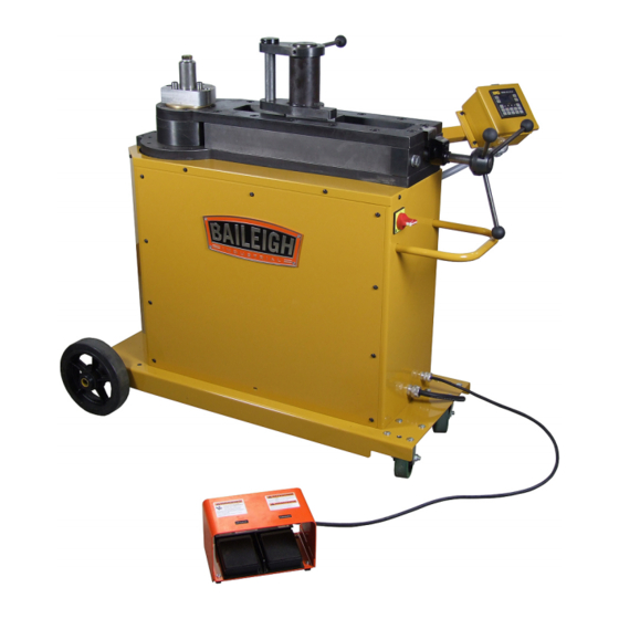
- Page 1 OPERATOR’S MANUAL ROTARY DRAW BENDER MODEL: RDB-325 (B8090) Rev. 03/2015 © 2015 Baileigh Industrial, Inc.
-
Page 2: Table Of Contents
Table of Contents INTRODUCTION ......................1 GENERAL NOTES ......................1 SAFETY INSTRUCTIONS ....................2 SAFETY PRECAUTIONS ....................5 TECHNICAL SPECIFICATIONS ..................7 UNPACKING AND CHECKING CONTENTS ..............8 Cleaning ........................8 TRANSPORTING AND LIFTING ..................9 INSTALLATION ....................... 9 ASSEMBLY AND SET UP .................... 10 GETTING TO KNOW YOUR MACHINE ............... - Page 3 INDEX TABLE ATTACHMENT (OPTIONAL EQUIPMENT) .......... 39 Introduction ........................ 39 Connection to Your Machine ..................39 Height Adjustment and Leveling ................39 Material Layout ......................40 IDX OPERATION ......................40 INDEX TABLE LAYOUT DIAGRAM (OPTIONAL EQUIPMENT) ........41 LUBRICATION AND MAINTENANCE ................42 Gear Box Oil ......................
-
Page 4: Introduction
INTRODUCTION The quality and reliability of the components assembled on a Baileigh Industrial machine guarantee near perfect functioning, free from problems, even under the most demanding working conditions. However if a situation arises, refer to the manual first. If a solution cannot be found, contact the distributor where you purchased our product. -
Page 5: Safety Instructions
Note: This symbol refers to useful information throughout the manual. IMPORTANT PLEASE READ THIS OPERATORS MANUAL CAREFULLY It contains important safety information, instructions, and necessary operating procedures. The continual observance of these procedures will help increase your production and extend the life of the equipment. SAFETY INSTRUCTIONS LEARN TO RECOGNIZE SAFETY INFORMATION This is the safety alert symbol. - Page 6 General precautions are listed on CAUTION safety signs. CAUTION also calls attention to safety messages in this manual. SAVE THESE INSTRUCTIONS. Refer to them often and use them to instruct others. PROTECT EYES Wear safety glasses or suitable eye protection when working on or around machinery.
- Page 7 BEWARE OF PINCH POINTS Keep hands and fingers away from the drive mechanisms, cylinders, ratchets, and other moving linkage while the machine is in operation. KEEP CLEAR OF MOVING OBJECTS Always be aware of the position of the material and the swing area in which the material will travel.
-
Page 8: Safety Precautions
SAFETY PRECAUTIONS Metal working can be dangerous if safe and proper operating procedures are not followed. As with all machinery, there are certain hazards involved with the operation of the product. Using the machine with respect and caution will considerably lessen the possibility of personal injury. However, if normal safety precautions are overlooked or ignored, personal injury to the operator may result. - Page 9 11. Do not overreach. Maintain proper footing and balance at all times. DO NOT reach over or across a running machine. 12. Stay alert. Watch what you are doing and use common sense. DO NOT operate any tool or machine when you are tired. 13.
-
Page 10: Technical Specifications
TECHNICAL SPECIFICATIONS Maximum Center Line Radius (CLR)* 16.5" (419mm) Minimum Center Line Radius (CLR)* .5" (12.7mm) Minimum OD .25" (6.35mm) Mild Steel Pipe (Schedule 80) 2" (50.8mm) Aluminum Pipe (Schedule 40) 2" (50.8mm) Stainless Steel Pipe (Schedule 40) 2" (50.8mm) Mild Steel Round Tube (Wall) 3"... -
Page 11: Unpacking And Checking Contents
UNPACKING AND CHECKING CONTENTS Your Baileigh machine is shipped complete in one crate. Separate all parts from the packing material and check each item carefully. Make certain all items are accounted for before discarding any packing material. WARNING: SUFFOCATION HAZARD! Immediately discard any plastic bags and packing materials to eliminate choking and suffocation hazards to children and animals. -
Page 12: Transporting And Lifting
TRANSPORTING AND LIFTING CAUTION: Lifting and carrying operations should be carried out by skilled workers, such as a truck operator. Make sure the machine is well balanced. Choose a location that will keep the machine free from vibration and dust from other machinery. Keep in mind that having a large clearance area around the machine is important for safe and efficient working conditions. -
Page 13: Assembly And Set Up
• Keep the floor free of oil and make sure it is not slippery. • Remove scrap and waste materials regularly, and make sure the work area is free from obstructing objects. • If long lengths of material are to be fed into the machine, make sure that they will not extend into any aisles. -
Page 14: Getting To Know Your Machine
GETTING TO KNOW YOUR MACHINE... -
Page 15: General Design Description
The simplicity of design and minimum effort required to operate the machine contributes towards meeting schedules and producing greater profits. The RDB-325 is an electric powered “Rotary Draw” bending machine. To bend material, a bending die and counter die are required. The material is hooked by the bending dies’ hook arm and is powerfully rotated in the clockwise direction. -
Page 16: Electrical
ELECTRICAL WARNING: Baileigh Industrial is not responsible for any damage caused by wiring up to an alternative 3-phase power source other than direct 3-phase. If you are using an alternate power source, consult a certified electrician or contact Baileigh Industrial prior to energizing the machine. -
Page 17: Plug Connection
WARNING: In all cases, make certain the receptacle in question is properly grounded. If you are not sure, have a qualified electrician check the receptacle • Improper connection of the equipment-grounding conductor can result in risk of electric shock. The conductor with insulation having an outer surface that is green with or without yellow stripes is the equipment-grounding conductor. -
Page 18: Operation
OPERATION CAUTION: Always wear proper eye protection with side shields, safety footwear, and leather gloves to protect from burrs and sharp edges. CAUTION: Keep hands and fingers clear of the dies and swing arms. Stand to the front of the machine to avoid getting hit with the material during the bending process. -
Page 19: Programmer Display And Key Functions
Programmer Display and Key Functions 1. The touch screen control is very self-explanatory. By touching the labeled touch boxes on the screen, the listed parameter or function will be selected. The exit box will return you to the previous screen and get you back to the RMD MAIN SCREEN. When entering names and degrees, a keypad will be displayed Fig 2, 3, and 4 to allow switching between alpha and numeric keys. -
Page 20: Main Menu Choices
Main Menu Choices 1. "RUN, VIEW OR EDIT A PROGRAM" Select this Feature if you want to: Run a program View the settings of an existing program Edit or create a program. a. Up to 170 programs with 10 bends per program can be created using any alphanumeric characters. -
Page 21: Edit A Program
Edit a Program 1. Select this feature when you want to edit an existing program. a. From the Program selector screen Fig 5, choose the program number to be edited. Use the up and down arrows to move the screen up or down one line or one page at a time. -
Page 22: Dry Running
4. After selecting the program line. Touch the EDIT button and the program parameters will be displayed Fig 6. Press the View button in the upper right corner to change to the Edit mode. 5. On the edit screen enter the desired PROGRAM NAME by touching the name field Fig. -
Page 23: Manual Bend
down one line or one page at a time. Dashed lines in the name indicate that no program is saved to that location. 3. After selecting the program touch the RUN button and the program parameters will be displayed Fig 7. 4. - Page 24 5. When the angle and speed settings have been entered, the bend may be dry run or an actual bend may be performed. Full Manual Mode Full Manual Mode allows for bending to any angle between 0.0 and 200.0 degrees with only the operator controlling the stop point.
-
Page 25: Homing
Homing IMPORTANT: Don’t Change the home position unless you are sure the position was lost, damage to the machine and tooling can occur if the home position is set incorrectly. 1. The machine has been homed from the factory and does not need to be re-homed unless the encoder or drive motor needs servicing. -
Page 26: Oem Screens And Bending More Than 180 Degrees
• Parameters in the OEM MENU should only be done after consulting the factory. Changing these parameters without consulting the factory will void the warranty. • This machine is capable of bending more than 180 degrees. Contact Baileigh Industrial about your application. -
Page 27: Oem Screen Shots
• Activation of bi directional option should only be done at the factory. Consult the factory for specific information. OEM Screen Shots OP Screen Figure 1 OEM Screen Figure 11 OEM Screen Figure 12 OEM Screen Figure 13... - Page 28 OEM Screen Figure 14 OEM Screen Figure 15 OEM Screen Figure 16 OEM Screen Figure 17...
- Page 29 OEM Screen Figure 18 OEM Screen Figure 19 OEM Screen Figure 20 OEM Screen Figure 21...
- Page 30 OEM Screen Figure 22...
-
Page 31: Understanding Springback
UNDERSTANDING SPRINGBACK Springback can be difficult to understand. As material is bent, the materials yield strength resists being formed. As a final degree is reached, the machine will have enough power to hold the bend at a set degree, but as the pressure of the machine is released, the material has a resistance built in, so it “springs back”... -
Page 32: Die Selection And Installation
Bronze Counter Die Insert “0” Mark Note: Pipe and Tube are not the same, (see table 1) for nominal pipe sizes. All BAILEIGH INDUSTRIAL dies are color coded to avoid confusion between pipe and tube (see table 2). IMPORTANT: Damaged or worn tooling should be replaced before attempting to bend material. - Page 33 Spindle Die Drive Pins 1/2-13 Tapped holes for bolting down dies Center Pin At “0” position, this flat is parallel with the machine side Hitch Pin 4. To install the counter die, remove the hitch pin and insert the counter die in the opening in the counter die mount until the 3/4”...
-
Page 34: Material Insertion
This software is available from Baileigh Industrial. Contact your distributor for availability. • Bending with a rotary draw bender requires determining the start of bend point which will line up with the “0”... - Page 35 6. With the counter die tight, document the number displayed on the Leadscrew counter, you will want to return to the same exact number every time to ensure exact counter die positioning and repeatable bends. This number can be entered in the control for programmed bends.
-
Page 36: Material Removal / Advancement
Left Right • In the left figure, there is not enough material to complete the bend. This bend will damage the dies. • The right figure shows a correct bending orientation. IMPORTANT: Orienting your tubing in this fashion will cause damage to your tooling and machine!! DO NOT pull bent tubing into the counter die! Make sure you have enough straight material on the draw side of the tube to create your bend. -
Page 37: Pipe And Tube Bending Diagrams
PIPE AND TUBE BENDING DIAGRAMS L = Arc length (outside) R = Rise (inside) D = Tube outside diameter t = Tube wall thickness a = First bend arc angle H = Height of offset b = Second bend arc angle L = Length of offset A = First tangent R1 = First radius... -
Page 38: Bending Glossary
BENDING GLOSSARY Arc Length The length of material along the centerline of the tubing Distance in inches from the center of curvature to the centerline Centerline Radius (CLR) axis of the tube bending or pipe bending bends. Abbreviated as CLR. See Tube Bending and Pipe Bending Diagram Angle in degrees to which the tube/pipe bends are formed (i.e. -
Page 39: Bending Suggestions
• If using BAILEIGH INDUSTRIAL’s standard counterdie is not producing desired results, roller counter dies are also available. • BAILEIGH INDUSTRIAL has both steel rollers as well as plastic rollers. Plastic rollers are used primarily for polished aluminum. Steel rollers would be used for non-polished materials. -
Page 40: Bending With Square Dies
Bending With Square Dies • Die Parts Main Bending Die Die Cap Quick Release Handles Hook-Arm Hook-Arm Clamp Plastic Slide Slide Mount Quick Release Studs Square Tooling Setup 1. Install the bending die (1) on to the spindle. Be careful not to pinch your fingers as you lower the die on to the spindle. -
Page 41: Large Size Square
If the square material slips in the hook arm, use the supplied clamp and bolts to hold in place. BAILEIGH INDUSTRIAL offer crush bend dies to form a concave crease on the inside of square bends to reduce the possibility of wrinkling. -
Page 42: Index Table Attachment (Optional Equipment)
INDEX TABLE ATTACHMENT (OPTIONAL EQUIPMENT) Introduction The IDX-10 Indexing table was designed to allow you too accurately and repeatedly position distances between bends, by using the adjustable stops. Also the IDX-10 can be used to hold the material being bent perfectly level while bending, or altering the angles between bends. Connection to Your Machine 1. -
Page 43: Material Layout
5. The previous steps are just examples how to set stops and produce various bends; it is up to the user to define exactly how their IDX will be set up. BAILEIGH INDUSTRIAL will be glad to offer any suggestions for your application. -
Page 44: Index Table Layout Diagram (Optional Equipment)
INDEX TABLE LAYOUT DIAGRAM (OPTIONAL EQUIPMENT) -
Page 45: Lubrication And Maintenance
LUBRICATION AND MAINTENANCE WARNING: Make sure the electrical disconnect is OFF before working on the machine. Maintenance should be performed on a regular basis by qualified personnel. Always follow proper safety precautions when working on or around any machinery. • Check daily for any unsafe conditions and fix immediately. •... -
Page 46: Electrical Schematic
ELECTRICAL SCHEMATIC Horner ( XLE or XLT) Hexle 102 or HE-XT102 Programmer Black J2 Connector Orange J1 Connector... -
Page 47: Electrical Components
Electrical Components WARNING: Make sure the electrical disconnect is OFF before working on the machine. Use the lockout provided on the main disconnect switch. Wait at least 1 min before working on any circuit, because the VFD capacitors may have energy stored. Maintenance should be performed on a regular basis by qualified personnel. -
Page 48: Troubleshooting
TROUBLESHOOTING FAULT PROBABLE CAUSE REMEDY Check input power and verify Wrong or non-existent input Machine does not power voltage power source. Blown fuse or Check and replace fuses. Reset tripped circuit breaker. circuit breakers Let oil purge from gearbox and Oil leaking from breather Normal expansion of gearbox oil take no further action. -
Page 49: Tables, Charts, & Diagrams
TABLES, CHARTS, & DIAGRAMS Table 1 Standard Pipe Sizes and Schedules PIPE O.D. Pipe Schedules and Wall Thickness SIZES XX STRONG 0.405 0.400 0.050 0.068 0.095 0.540 0.500 0.070 0.088 0.119 0.675 0.500 0.070 0.091 0.126 0.840 0.700 0.080 0.109 0.147 0.188 0.294... - Page 50 Table 3 ARC LENGTH TABLE EXAMPLE: Arc Length = Constant x Bend Radius. Example: 90deg bend with 6” clr EXAMPLE: 1.575 (from table) x 6” (clr) = 9.45” (Arc Length) For bends more than 90deg, Constants can be added together. Degrees Constant Degrees...
-
Page 51: Diagram 1
Diagram 1... -
Page 52: Diagram2
Diagram2... -
Page 53: Parts Diagram
PARTS DIAGRAM Base Assembly Parts Diagram... -
Page 54: Control Box Parts Diagram
Control Box Parts Diagram... -
Page 55: Drive Assembly Parts Diagram
Drive Assembly Parts Diagram... -
Page 56: Main Bending Assembly Parts Diagram
Main Bending Assembly Parts Diagram... -
Page 57: Parts List
Parts List Item Part Number Description Qty. PP-0653 1.875 O.D. X 1.25 I.D. X 1.875 LNG. PP-0147 Wheel PP-0138 1.25" Set Screw Collar PP-0139 Caster Wheel Imperial .375-16 X 1 Carriage Bolt Imperial .375 Lockwasher Imperial .375-16 Hex Nut ME-M200-7A005 Stand Off M6 X 1.0 X 14 Hex Flange... - Page 58 Item Part Number Description Qty. M350-5A027 Box Arm ME-M350-6A120 Box Arm Base Plate M8 X 1.25 X 16 SHCS ME-M350-7A057 Electrical Box Pivot Hub M10 X 1.5 X 8 Set Screw M350-7A058 Electrical Box Washer M250-6A021 Touch Screen Enclosure Imperial 1.50 Ext.
- Page 59 Item Part Number Description Qty. M325-5A003 M325 Cabinet Assembly M325-6A007 M325 Rear Brace PP-0141 3.50 O.D. X 3.0 I.D. X 2.50 LNG ME-M400-7A003-3 Spider Hub M400-7A012 Large Thrust Washer ME-M325-7A001 M325/M350 Spindle PP-0118 3.0" Clamp Collar ME-M350-7A046 Lead Screw Nut M500-7A005 Lead Screw ME-M350-7A047...
- Page 61 General Machinery Safety Instructions Machinery House requires you to read this entire Manual before using this machine. 1. Read the entire Manual before starting 14. Use correct amperage extension cords. machinery. Machinery may cause serious injury if Undersized extension cords overheat and lose not correctly used.
- Page 62 Elec/Mech Pipe/Tube Bender Safety Instructions Machinery House requires you to read this entire Manual before using this machine. 1. Maintenance. 10. Avoiding Entanglement. Make sure the Pipe/Tube Bender Pipe/Tube Bender guards is turned off and disconnect from the main power must be used at all times.
Need help?
Do you have a question about the RDB-325 and is the answer not in the manual?
Questions and answers