Table of Contents
Advertisement
Quick Links
OPERATOR'S MANUAL
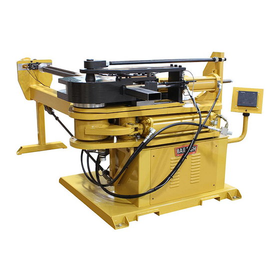
RECTANGULAR TUBE MANDREL BENDER
MODEL: MB-4X2
Baileigh Industrial, Inc.
P.O. Box 531
Manitowoc, WI 54221-0531
Phone: 920.684.4990
Fax: 920.684.3944
sales@baileigh.com
REPRODUCTION OF THIS MANUAL IN ANY FORM WITHOUT WRITTEN APPROVAL OF BAILEIGH INDUSTRIAL, INC.
IS PROHIBITED. Baileigh Industrial, Inc. does not assume and hereby disclaims any liability for any damage or loss
caused by an omission or error in this Operator's Manual, resulting from accident, negligence, or other occurrence.
Rev. 08/2016
© 2016 Baileigh Industrial, Inc.
Advertisement
Table of Contents

Subscribe to Our Youtube Channel
Related Manuals for Baileigh Industrial MB-4X2


Summary of Contents for Baileigh Industrial MB-4X2
- Page 1 REPRODUCTION OF THIS MANUAL IN ANY FORM WITHOUT WRITTEN APPROVAL OF BAILEIGH INDUSTRIAL, INC. IS PROHIBITED. Baileigh Industrial, Inc. does not assume and hereby disclaims any liability for any damage or loss caused by an omission or error in this Operator’s Manual, resulting from accident, negligence, or other occurrence.
-
Page 2: Table Of Contents
Table of Contents THANK YOU & WARRANTY ..................1 INTRODUCTION ......................3 GENERAL NOTES ......................3 SAFETY INSTRUCTIONS ....................4 SAFETY PRECAUTIONS ....................7 Dear Valued Customer: ....................7 TECHNICAL SPECIFICATION ..................9 TECHNICAL SUPPORT ....................9 UNPACKING AND CHECKING CONTENTS ..............10 Cleaning ........................ - Page 3 CONTROL BOX ASSEMBLY ..................46 Parts List ........................47 ORIGINAL PRESSURE DIE PARTS DIAGRAM ............53 Original Pressure Die Parts List ................. 54...
-
Page 4: Thank You & Warranty
THANK YOU & WARRANTY Thank you for your purchase of a machine from Baileigh Industrial. We hope that you find it productive and useful to you for a long time to come. Inspection & Acceptance. Buyer shall inspect all Goods within ten (10) days after receipt thereof. Buyer’s payment shall constitute final acceptance of the Goods and shall act as a waiver of the Buyer’s rights to inspect or... - Page 5 A 30% re-stocking fee applies to all returns. Baileigh Industrial makes every effort to ensure that our posted specifications, images, pricing and product availability are as correct and timely as possible. We apologize for any discrepancies that may occur. Baileigh Industrial reserves the right to make any and all changes deemed necessary in the course of business including but not limited to pricing, product specifications, quantities, and product availability.
-
Page 6: Introduction
After receiving your equipment remove the protective container. Do a complete visual inspection, and if damage is noted, photograph it for insurance claims and contact your carrier at once, requesting inspection. Also contact Baileigh Industrial and inform them of the unexpected occurrence. Temporarily suspend installation. -
Page 7: Safety Instructions
IMPORTANT PLEASE READ THIS OPERATORS MANUAL CAREFULLY It contains important safety information, instructions, and necessary operating procedures. The continual observance of these procedures will help increase your production and extend the life of the equipment. SAFETY INSTRUCTIONS LEARN TO RECOGNIZE SAFETY INFORMATION This is the safety alert symbol. - Page 8 SAVE THESE INSTRUCTIONS. Refer to them often and use them to instruct others. PROTECT EYES Wear safety glasses or suitable eye protection when working on or around machinery. PROTECT AGAINST NOISE Prolonged exposure to loud noise can cause impairment or loss of hearing.
- Page 9 KEEP CLEAR OF MOVING OBJECTS Always be aware of the position of the material and the swing area in which the material will travel. The material will swing with significant force. This swing area will create pinch points and the force of the material movement may cause serious bodily injuries.
-
Page 10: Safety Precautions
SAFETY PRECAUTIONS Metal working can be dangerous if safe and proper operating procedures are not followed. As with all machinery, there are certain hazards involved with the operation of the product. Using the machine with respect and caution will considerably lessen the possibility of personal injury. However, if normal safety precautions are overlooked or ignored, personal injury to the operator may result. - Page 11 7. Do not force tool. Your machine will do a better and safer job if used as intended. DO NOT use inappropriate attachments in an attempt to exceed the machines rated capacity. 8. Use the right tool for the job. DO NOT attempt to force a small tool or attachment to do the work of a large industrial tool.
-
Page 12: Technical Specification
TECHNICAL SPECIFICATION Working Table Size* Depends on length chosen Bend Capacity Square 3" x 3" x 11ga. (76.2 x 76.2 x 3mm) Rectangle Capacity 2" x 4" x 11ga. (50.8 x 101.6 x 3mm) Hardway Degree of Bend (Maximum) 100° Bend Direction Clockwise Maximum Bend Speed... -
Page 13: Unpacking And Checking Contents
UNPACKING AND CHECKING CONTENTS Your Baileigh machine is shipped complete. Separate all parts from the packing material and check each item carefully. Make certain all items are accounted for before discarding any packing material. WARNING: SUFFOCATION HAZARD! Immediately discard any plastic bags and packing materials to eliminate choking and suffocation hazards to children and animals. -
Page 14: Transporting And Lifting
TRANSPORTING AND LIFTING CAUTION: Lifting and carrying operations should be carried out by skilled workers, such as a truck operator. Make sure the machine is well balanced. Choose a location that will keep the machine free from vibration and dust from other machinery. - Page 15 Keep the floor free of oil and make sure it is not slippery. Remove scrap and waste materials regularly, and make sure the work area is free from obstructing objects. If long lengths of material are to be fed into the machine, make sure that they will not extend into any aisles.
-
Page 16: Overall Dimensions
OVERALL DIMENSIONS... -
Page 20: Unpacking & Checking Contents
UNPACKING & CHECKING CONTENTS 1. Separate all contents from packing material; separate the machine and table from skids. 2. Move the machine and table to the desired area. Make sure area has plenty of work area around the machine with ample lighting. 3. -
Page 21: Installation/ Assembly
INSTALLATION/ ASSEMBLY 1. First, the machine itself needs to be leveled without the table. Use the provided foot pegs and level the machine. It is recommended that machines with a 20-foot index table be bolted or securely fastened to the concrete floor. 2. -
Page 22: Electrical
ELECTRICAL WARNING: Baileigh Industrial is not responsible for any damage caused by wiring up to an alternative 3-phase power source other than direct 3-phase. If you are using an alternate power source, consult a certified electrician or contact Baileigh Industrial prior to energizing the machine. -
Page 23: Plug Connection
WARNING: In all cases, make certain the receptacle in question is properly grounded. If you are not sure, have a qualified electrician check the receptacle Improper connection of the equipment-grounding conductor can result in risk of electric shock. The conductor with insulation having an outer surface that is green with or without yellow stripes is the equipment-grounding conductor. -
Page 24: Setup Guide
SETUP GUIDE CAUTION: Always wear proper eye protection with side shields, safety footwear, and leather gloves to protect from burrs and sharp edges. When handling large heavy materials make sure they are properly supported. TOOLING REMOVAL 1. Remove the wiper die assembly. 2. - Page 25 that there won’t be any interference with the material. Final adjustment of the pressure die assembly will come later on in tooling setup. (see step 17) (Fig. 5. - ¼ - ½” gap between material and pressure die.) 7. Install the correct mandrel; we will set the distance later. 8.
- Page 26 14. Make sure the tube sample is correctly in the die and select “Mandrel” on the rotary switch and press “Extend” it may want to push the tube, that’s normal. Once fully extended, push the tube back into the machine if needed. 15.
- Page 27 20. The only setting left is the mandrel, using the selector switch select “Mandrel” and press retract, now pressure die “Retract”, and finally clamp “Retract”, we now have to repeat the mandrel extend, once extended turn the pump switch off and remove the material. The mandrel setting is critical, so the body of the mandrel needs to protrude ¼- ½...
-
Page 28: Bending In Single Bend Mode
21) Press retract for the mandrel and the machine is now ready for bending. (Fig. 10) (Fig.10- All axis’ extended, ready for bending.) BENDING IN SINGLE BEND MODE 1. Mandrel lubrication is critical, so at this point with the pump off, apply liberal amounts of lube to the mandrel covering all sides. -
Page 29: Auto Sequence Mode
*CLOCKWISE=FASTER* *COUNTERCLOCKWISE=SLOWER* SPEED ADJUSTMENT SCREW 11. Continue to hold the pedal down until the bend is complete, “unless something goes wrong”. 12. When the bend is at the final degree setting, the axis’s can be opened up, the mandrel should always come out first, press the “Retract” button, once completed, the selector will automatically switch to pressure die, press the “Retract”... -
Page 30: Multi Bend Mode
completed. When the machine reaches the final degree setting the auto sequence will take over and start with retracting the mandrel, then the pressure die and finally the clamp die. 4. You are now ready to advance the material for the next bend. MULTI BEND MODE 1. -
Page 31: Bending Allowance
12. Once in Multi bend mode and running parts, you should never have to touch the screen again until a change is made, otherwise it will continue to cycle thru the bends. CAUTION: When repositioning material always keep your hands away from the clamping and bending zone, especially when in auto sequence mode! 13. -
Page 32: Lubrication And Maintenance
LUBRICATION AND MAINTENANCE WARNING: Make sure the electrical disconnect is OFF before working on the machine. Maintenance should be performed on a regular basis by qualified personnel. Always follow proper safety precautions when working on or around any machinery. Daily ... -
Page 33: Hydraulic System Maintenance
Hydraulic System Maintenance This machine utilizes a self-contained hydraulic power unit; it is used to supply hydraulic pressure to 3 individual hydraulic circuits, the clamp die, mandrel extraction shaft and the pressure die. They system pressure is set to 2800 psi. 3000 psi is the maximum output of this unit and is not recommended as the operating pressure. -
Page 34: Hydraulic Schematic
HYDRAULIC SCHEMATIC... -
Page 35: Hydraulic Components
Hydraulic Components Item Part Number Description Qty. R978812487 Reservoir 5PUA40-15 STD. R978813462 Reservoir Cover 5 Gal Opt 2 3+5hp Rev1 R978805330 Motor B5H1800R184TCNFT230/460/3/60 TEFC R978802995 Coupler HUB L095 Bored 1-1/8x1/4 key 33-20 R978807566 Coupler HUB L095 SPL SAE A 33-20 R978889101 Coupler Insert L090/095 Hytrel 9510290015... -
Page 36: Electrical Schematic
ELECTRICAL SCHEMATIC... -
Page 39: Trouble Shooting
Trouble Shooting Problem Causes Wrinkles on the inside of the bend Wiper die has too much Rake Wiper die is not close enough to tangent Not enough pressure on pressure die Wrong size mandrel Clamp die slipping Too much wiper die lube Wall thickness of tubing doesn't match mandrel size Clamp Die Slipping Not enough pressure... -
Page 40: Cart Assembly
CART ASSEMBLY... -
Page 41: Main Frame Assembly
MAIN FRAME ASSEMBLY... -
Page 42: Spindle Stack Assembly
SPINDLE STACK ASSEMBLY... -
Page 43: Swing Arm Assembly
SWING ARM ASSEMBLY... -
Page 44: Modified Pressure Die Assembly
MODIFIED PRESSURE DIE ASSEMBLY... -
Page 45: Strut Bar Assembly
STRUT BAR ASSEMBLY... -
Page 46: Encoder Assembly
ENCODER ASSEMBLY... -
Page 47: Mandrel Table Assembly
MANDREL TABLE ASSEMBLY... -
Page 48: Mandrel Extraction Cylinder Assembly
MANDREL EXTRACTION CYLINDER ASSEMBLY... -
Page 49: Control Box Assembly
CONTROL BOX ASSEMBLY... -
Page 50: Parts List
Parts List Item Part Number Description Qty. M550-5A003 M550 Cabinet PP-0022 1/2" Elbow PP-0290 3/4" Cord Grip PP-0023 Cord Grip PP-1662 4 Wire Cord Grip PP-1661 6 Wire Cord Grip M550-6A069 Cabinet Cover BS-0323 Foot Pad Shaft M350-7A071 Leveling Foot 5/8-11 Hex Nut M6 X 1.0 X 10... - Page 51 Item Part Number Description Qty. M20 X 2.5 X 45 SHCS M20 X 2.5 X 65 SHCS M16 X 2.0 X 40 SHCS M10 X 1.5 X 40 SHCS M16 X 2.0 X 55 Hex Flange M550-6A015 Angle Brace M550-6A048 Triangle Brace M16 X 2.0 X 60 SHCS...
- Page 52 Item Part Number Description Qty. M12 X 1.75 X 30 SHCS PP-1577 Encoder M550-6A051 Encoder Mounting Bracket #4-40 X .25 SHCS M5 X 0.8 X 6 Set Screw M8 X 1.25 X 10 Button Head PP-1576 Encoder Belt PP-1564 5 X 18 Bend Cylinder STD.
- Page 53 Item Part Number Description Qty. M550-6A094 Pressure Die Main Block M550-6A095 Top Cap M550-6A096 Pressure Die Mount M550-6A097 Guide Bar M550-6A098 Pressure Die End Block M550-6A099 Slide Key M12 X 1.75 X 35 SHCS M12 X 1.75 X 35 Hex Flange M10 X 1.5 X 35 SHCS M16 X 2.0 X 150...
- Page 54 Item Part Number Description Qty. PB24-7A022 Washer 2.5" EXT. RETAINING RING Std. 1.25-12 Hex Nut M550-6A066 Angle Bracket M550-6A067 Wiper Mount Easy Way M550-6A092 Wiper Mount Hard Way M12 X 1.75 X 40 Hex Flange PP-1276 #6 Threaded Elbow PP-1680 #6 Female Straight Swivel Fitting PP-1724 #6 Male 'T' Fitting...
- Page 55 Item Part Number Description Qty. M550-5A016 3.0 Pressure Die Assist Cylinder M550-7A046 Switch Disc M550-7A048 Mandrel Extract Switch Shaft M550-5A006 Proximity Sensor Mount M550-7A031 Rotatable Nut M550-7A038 Lock Ring M550-7A044 Custom U-Joint M6 X 1.0 X 8 Set Screw M8 X 1.25 X 25 SHCS M350-7A022 Mandrel Extract Shaft...
-
Page 56: Original Pressure Die Parts Diagram
ORIGINAL PRESSURE DIE PARTS DIAGRAM... -
Page 57: Original Pressure Die Parts List
Original Pressure Die Parts List M550-6A006-V2 SLIDE BLOCK PP-0674 1.0" CAM FOLLOWER PP-1572 CAM FOLLOWER #CFH-1.5-B M550-6A009 PRESSURE DIE MOUNT M550-6A010 PRESSURE DIE BLOCK M550-6A043 TOP BEARING CAP M550-6A052 LOCK KEY M550-6A060 SLIDE KEY M550-6A022 PRESSURE DIE END BLOCK PP-0842 1.25 ID X 1.50 OD X 1.0 LNG BUSHING M550-7A076 CAM FOLLOWER STUD... - Page 58 NOTES...
- Page 59 NOTES...
Need help?
Do you have a question about the MB-4X2 and is the answer not in the manual?
Questions and answers