Table of Contents
Advertisement
Quick Links
POH
Section 0
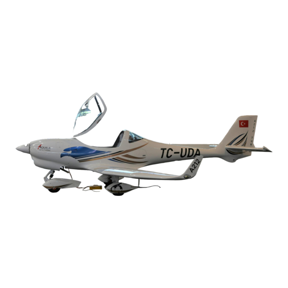
AQUILA AT01-200C
INTRODUCTION
With the AQUILA AT01 you have acquired a very efficient training and utility aircraft, which is
easy to operate and exhibits excellent handling qualities.
To ensure reliable operation and trouble free flight, we recommend that you read this Pilot's
Operating Handbook thoroughly and adhere to the operating instructions and recommendations
given herein.
CAUTION
All limitations, procedures and performance data contained in this handbook are EASA
approved and mandatory. Failing to follow the procedures and limits set forth in this handbook
can lead to a loss of liability by the manufacturer.
THE HANDBOOK
The handbook is presented in loose-leaf form to ease the substitution of revisions and is sized
in A5-format for convenient storage in the aircraft.
Tab dividers throughout the handbook allow quick reference to each section. A Table of
Contents is located at the beginning of each section to aid the location of specific data within
that section.
All rights reserved.
Reproduction or disclosure to third parties of this document or any part thereof is not permitted,
except with the prior and express written permission of AQUILA Aviation International GmbH.
Copyright © by
Aviation International GmbH
Schönhagen, Germany
Document Nr.:
Issue:
Supersedes Issue:
Date:
Page:
FM-AT01-1010-106
A.02
A.01 (02.03.2020)
03.03.2021
0 – 1
Advertisement
Table of Contents

Subscribe to Our Youtube Channel
Related Manuals for Aquila AT01-200C


Summary of Contents for Aquila AT01-200C
- Page 1 AQUILA AT01-200C INTRODUCTION With the AQUILA AT01 you have acquired a very efficient training and utility aircraft, which is easy to operate and exhibits excellent handling qualities. To ensure reliable operation and trouble free flight, we recommend that you read this Pilot's Operating Handbook thoroughly and adhere to the operating instructions and recommendations given herein.
-
Page 2: Issue
Section 0 AQUILA AT01-200C TABLE OF CONTENTS SECTION GENERAL OPERATING LIMITATIONS (approved section) EMERGENCY PROCEDURES (approved section) NORMAL PROCEDURES (approved section) PERFORMANCE (partly approved section) WEIGHT AND BALANCE AIRCRAFT DESCRIPTION HANDLING AND MAINTENANCE SUPPLEMENTS Document Nr.: Issue: Supersedes Issue: Date:... -
Page 3: Aquila At01-200C (N/Vfr)
Section 0 AQUILA AT01-200C LIST OF EFFECTIVE PAGES Note: If the applicable POH supplement for Night VFR operation is implemented, the list of resulting effective chapters can be found in chapter 9. Section Issue Approved Page Date A.02 0-1 to 0-6 03.03.2021... -
Page 4: Editorial Changes
Generally only complete sections of the POH will be exchanged and not individual pages. The operation of the AQUILA AT01 is only permitted with a current and up to date POH carried on board. Please refer to the following web page whenever the revision status of your POH is in question. - Page 5 Section 0 AQUILA AT01-200C The technical content of this document is approved under the authority of the DOA ref. EASA.21J.025. Document Nr.: Issue: Supersedes Issue: Date: Page: FM-AT01-1010-106 A.02 A.01 (02.03.2020) 03.03.2021 0 – 5...
- Page 6 AVAILABILITY OF TECHNICAL PUBLICATIONS To guarantee safe operation and correct maintenance of the AQUILA AT01-200 aircraft, all manuals and technical publications must be kept in the current effective status. All manuals and technical publications are available from the companies listed below:...
- Page 7 1.4.1 Overall Dimensions 1.4.2 Wings 1.4.3 Horizontal Stabilizer / Elevator 1.4.4 Fuselage and Vertical Stabilizer / Rudder 1.4.5 Landing Gear AQUILA AT01-200 – THREE VIEW DRAWING ENGINE PROPELLER FUEL OIL AND COOLANT 1.9.1 Engine Oil 1.9.2 Engine Coolant 1.10 WEIGHTS 1.11...
- Page 8 This Pilot's Operating Handbook contains all the information the pilot and instructor require for the safe and efficient operation by day and night of the AQUILA AT01-200 aircraft. It includes all information required in accordance with JAR-VLA and additional information considered by the manufacturer to be of value to the pilot.
- Page 9 Section 1 AQUILA AT01-200C (N/VFR) GENERAL WARNING, CAUTIONS AND NOTES Throughout the text, special text boxes marked WARNING, CAUTION and NOTE are used. These terms are defined as follows: WARNING Procedures, practices, etc. which may result in personal injury or loss of life if not strictly adhered to.
- Page 10 Section 1 AQUILA AT01-200C (N/VFR) GENERAL PRINCIPLE AIRCRAFT DIMENSIONS 1.4.1 Overall Dimensions Wing Span: 33.79 ft (10.30 m) Length: 24.28 ft (7.40 m) Height: 7.87 ft (2.40 m) 1.4.2 Wings Airfoil: HQ-XX mod. Area: 113.02 sq. ft (10.50 m²) Aspect Ratio: 10.10...
- Page 11 Section 1 AQUILA AT01-200C (N/VFR) GENERAL AQUILA AT01-200 – THREE VIEW DRAWING Document Nr.: Issue: Supersedes Issue: Date: Page: FM-AT01-1010-281 A.02 A.01 (02.03.2020) 03.03.2021 1 - 5...
- Page 12 Section 1 AQUILA AT01-200C (N/VFR) GENERAL ENGINE The ROTAX 914 F3 is a 4-cylinder 4-stroke engine with air cooled cylinders and liquid cooled ® cylinder heads. The Propeller is driven via an internal reduction gearbox with an integrated overload clutch and a hydraulic constant speed propeller governor.
- Page 13 Section 1 AQUILA AT01-200C (N/VFR) GENERAL ENGINE OIL AND COOLANT 1.9.1 Engine Oil Use only oil with an API classification of “SG” or higher. Heavy duty 4-stroke motor oils tend to meet these requirements. For more information regarding engine oil selection, please refer to the Operator’s Manual for all versions of the 914 engine series and to the current issue of the...
- Page 14 Section 1 AQUILA AT01-200C (N/VFR) GENERAL 1.9.2 Engine Coolant A conventional, ethylene glycol and water based coolant is used. Please refer to the Operator’s Manual for the 914 engine series, section 2.2, and to the current issue of the ROTAX Service Instructions SI-914-019 when choosing an engine coolant.
- Page 15 Section 1 AQUILA AT01-200C (N/VFR) GENERAL 1.11 TERMINOLOGY AND ABBREVIATIONS 1.11.1 Speeds IAS: (Indicated Airspeed) - the speed shown on the airspeed indicator KIAS: IAS expressed in knots CAS: (Calibrated Airspeed) - the indicated airspeed, corrected for position and instrument error. CAS is equal to true airspeed in standard atmosphere conditions at sea level.
- Page 16 Section 1 AQUILA AT01-200C (N/VFR) GENERAL 1.11.2 Weight and Balance Reference Datum: imaginary vertical plane from which horizontal distances are measured for balance purposes Reference Line: fixed horizontal reference line Lever Arm: The horizontal distance from the reference datum to the center of gravity (C.G.) of an item...
- Page 17 Section 1 AQUILA AT01-200C (N/VFR) GENERAL 1.11.4 Engine and Performance TOP: (Take-off Power) - maximum power permissible for takeoff MCP: (Max. Continuous Power) - maximum power permitted for continuous operation 1.11.5 Various Serial No. (S/N): Serial Number of the Aircraft Part No.
- Page 18 Section 1 AQUILA AT01-200C (N/VFR) GENERAL 1.12 CONVERSION FACTORS 1.12.1 Length 1 ft 0.304 1 in 25.4 1.12.2 Speed 1 kt 1.852 km/h 1 mph 1.609 km/h 1.12.3 Pressure 1 hPa N/m² 1 mbar 1 in. Hg 33.865 1 psi 68.97...
- Page 19 Section 2 AQUILA AT01-200C (N/VFR) LIMITATIONS SECTION 2 LIMITATIONS Page INTRODUCTION AIRSPEED LIMITATIONS AIRSPEED INDICATOR MARKINGS POWER PLANT LIMITATIONS 2.4.1 Engine 2.4.2 Propeller MARKINGS ON THE GLASS PANEL ENGINE MONITOR MVP-50P-AQ WEIGHT LIMITS CENTER OF GRAVITY LIMITS MANEUVER LIMITS FLIGHT LOAD FACTORS 2.10...
- Page 20 Section 2 AQUILA AT01-200C (N/VFR) LIMITATIONS INTRODUCTION This section includes all operating limitations, instrument markings and basic placards necessary for the safe operation of the aircraft, its engine, standard systems and standard equipment. WARNING The aircraft must be operated in compliance with the operating limitations.
- Page 21 Section 2 AQUILA AT01-200C (N/VFR) LIMITATIONS AIRSPEED INDICATOR MARKINGS The airspeeds given below are expressed in Indicated Airspeeds (IAS): Marking (IAS) [kts] Remarks White arc Full flap operating range 39-90 Green arc Normal operating range 49-130 Operations in this region must be conducted with...
- Page 22 Section 2 AQUILA AT01-200C (N/VFR) LIMITATIONS Oil Pressure Minimum: 11.6 psi (0.8 bar) below 590 RPM Normal: 29 –72.5 psi (2.0-5.0 bar) above 590 RPM Maximum during a cold start: 101.5 psi (7.0 bar) (only for a short time) Fuel Pressure* Minimum: 2.2 psi...
- Page 23 Section 2 AQUILA AT01-200C (N/VFR) LIMITATIONS 2.5 MARKINGS ON THE ENGINE MONITOR MVP-50P-AQ The following table shows the instrument markings shown on the MVP-50P-AQ and their meaning. Green Arc Red Line Yellow Arc Red Line (normal MVP-50P-AQ (minimum) (caution) (maximum)
- Page 24 Section 2 AQUILA AT01-200C (N/VFR) LIMITATIONS WEIGHT LIMITS Maximum Takeoff Weight 1653 lb (750 kg) Maximum Landing Weight 1653 lb (750 kg) Max. Weight in Baggage Compartment 88.2 lb ( 40 kg) WARNING Exceeding the weight limits can overload the aircraft and is prohibited. In addition, aircraft performance and handling characteristics may be detrimentally affected.
- Page 25 Section 2 AQUILA AT01-200C (N/VFR) LIMITATIONS NOTE All acrobatic maneuvers as well as maneuvers with a bank angle exceeding 60° are prohibited. FLIGHT LOAD FACTORS The following flight load factors may not be exceeded while performing any approved maneuvers. Flight Load Factor...
- Page 26 Section 2 AQUILA AT01-200C (N/VFR) LIMITATIONS 2.11 KINDS OF OPERATION LIMITS / MINIMUM EQUIPMENT Certified for: visual flights by Day and Night Table 1 For VFR by Day and Night* • Garmin G500 TXi Flight and navigational instruments • Magnetic Compass •...
- Page 27 2.14 OPERATING ALTITUDE The Aquila AT01-200 has a maximum operating altitude of 16,400 ft. For flights over FL120 an appropriate oxygen supply for all persons aboard is recommended. Furthermore national regulations may be considered if applicable.
- Page 28 Section 2 AQUILA AT01-200C (N/VFR) LIMITATIONS 2.15 PLACARDS 1) On the instrument panel, in the lower middle section of the panel: 2) On the instrument panel below the Airspeed Indicator: 3) On the inner surface of the baggage compartment door: 4) On the instrument panel next to the main switches: Document Nr.:...
-
Page 29: Table Of Contents
Section 4 AQUILA AT01-200C NORMAL PROCEDURES SECTION 4 NORMAL PROCEDURES Page INTRODUCTION AIRSPEEDS FOR NORMAL OPERATION DAILY INSPECTION PRE-FLIGHT INSPECTION CHECKLISTS FOR NORMAL PROCEDURES 4-11 4.5.1 Before Engine Start-up 4-11 4.5.2 Engine Start-up 4-12 4.5.3 Before Taxiing 4-13 4.5.4 Taxiing 4-13 4.5.5... -
Page 30: Normal Procedures
Section 4 AQUILA AT01-200C NORMAL PROCEDURES INTRODUCTION This section provides normal operating procedures and checklists for the aircraft as well as recommended airspeeds. Additional information is provided in the current issues of the Operators Manual for ROTAX engine Type 914 series and the Operation and Installation Manual of mt-Propeller ATA 61-01- 024. -
Page 31: Airspeeds For Normal Operation
Section 4 AQUILA AT01-200C NORMAL PROCEDURES AIRSPEEDS FOR NORMAL OPERATION The following airspeeds are based on the maximum take-off weight of 1653 lbs (750 kg). They may also be used for any lower operational weight. TAKE-OFF Airspeed (IAS) Normal climb speed to 50 Feet... -
Page 32: Daily Inspection
Section 4 AQUILA AT01-200C NORMAL PROCEDURES DAILY INSPECTION CAUTION The daily inspection is begun by checking all 3 fuel sumps for water and contamination. This must be done before the aircraft is moved. Otherwise the fuel in the sump may mix. - Page 33 Section 4 AQUILA AT01-200C NORMAL PROCEDURES B) EXTERIOR CHECK, Visual Inspection CAUTION In this manual, visual inspection means the following: Inspect for mechanical damage, dirt, cracks, delamination, excessive play, looseness, leaks, incorrect attachment, foreign objects and general condition. Control surfaces: in addition, check for free movement.
- Page 34 Section 4 AQUILA AT01-200C NORMAL PROCEDURES Left main landing gear a) Landing gear strut Visual inspection b) Wheel fairing Visual inspection (refer to 7.11.4) c) Tire pressure and slip marking CHECK d) Tire, wheel, brake Visual inspection e) Chocks (if in use)
- Page 35 Section 4 AQUILA AT01-200C NORMAL PROCEDURES Nose landing gear a) Nose gear strut Visual inspection b) Wheel fairing Visual inspection CAUTION Both parts of the 2 piece nose wheel fairing must always be installed on the aircraft c) Tire pressure and slip marking...
- Page 36 Section 4 AQUILA AT01-200C NORMAL PROCEDURES b) Check coolant level: Verify coolant level expansion tank replenish required. (The expansion tank must least 2/3 filled or coolant has to be visible at the gauge glass.) Verify coolant level overflow bottle replenish required.
-
Page 37: Pre-Flight Inspection
Section 4 AQUILA AT01-200C NORMAL PROCEDURES PRE-FLIGHT INSPECTION (Walk Around) Daily Inspection Confirm has been carried out. Tow bar Removed? Fuel level CHECK with dipstick and verify with the indicated fuel level on the fuel gauge WARNING Before cranking the propeller: Ignition, ALT1/BAT switch and ALT2/BAT2 switch: OFF Set the parking brake. - Page 38 Section 4 AQUILA AT01-200C NORMAL PROCEDURES 6. Tie-down straps remove 7. Baggage door CHECK if closed and locked 8. Pitot cover remove 9. Control locks remove 10. Seating position adjust and lock, check that nose wheel steering and brakes can be operated 11.
-
Page 39: Checklists For Normal Procedures
Section 4 AQUILA AT01-200C NORMAL PROCEDURES CHECKLISTS FOR NORMAL PROCEDURES 4.5.1 Before Engine Start-up Daily and Pre-Flight Inspection COMPLETED Passenger Briefing COMPLETED Seats ADJUSTED Seat Belts and Harnesses FASTENED Canopy CLOSED and LOCKED Check locking mechanism Parking Brake SET (pull lever back) -
Page 40: Engine Start-Up
Section 4 AQUILA AT01-200C NORMAL PROCEDURES 4.5.2 Engine Start-up Fuel Pump AUX switch Fuel Pressure within GREEN range (AUX pump OK) Fuel Pump AUX switch ALT2 / BAT2 switch ALT2 warning light ILLUMINATES Fuel pressure within GREEN range (MAIN pump OK) -
Page 41: Before Taxiing
Section 4 AQUILA AT01-200C NORMAL PROCEDURES 4.5.3 Before Taxiing CAUTION Engine run for approx. 2 min at 800 RPM and then at 1000 RPM for Oil Temp 122°F (50°C) Avionics switch Avionics and flight instruments The GARMIN G500 TXi has an integrated sensor that automatically adjusts the brightness of the display. -
Page 42: Before Take-Off (At The Taxi Holding Position)
Section 4 AQUILA AT01-200C NORMAL PROCEDURES 4.5.5 Before Take-off (at the Taxi Holding Position) Brakes APPLY and HOLD Parking Brake Compass and gyro Instruments CHECK setting Fuel Selector Valve LEFT or RIGHT, switch to the fuller tank Fuel Pressure CHECK if in the GREEN range... -
Page 43: Take-Off
Section 4 AQUILA AT01-200C NORMAL PROCEDURES 4.5.6 Take-off (up to 50 ft) CAUTION To increase power setting raise RPM first and open throttle second. To decrease power setting close throttle first and lower RPM second. Throttle WIDE OPEN (TOP = 115% MCP) -
Page 44: Cruise
Section 4 AQUILA AT01-200C NORMAL PROCEDURES 4.5.8 Cruise Throttle AS REQUIRED (Ref. to Section 5, Page 5-11) Propeller control lever SET 1650 to 2260 RPM CAUTION Continuous operation with throttle wide open and propeller revolution below 2140 RPM should be avoided to prevent engine damage in particular at pressure altitudes below 3000ft and at... -
Page 45: Landing
Section 4 AQUILA AT01-200C NORMAL PROCEDURES 4.5.10 Landing Lap belt CHECK SECURE Fuel Pump AUX switch Carburetor heat PULL (ON) Throttle AS REQUIRED Airspeed 90 KIAS Flaps switch T/O or LDG Trim switch AS REQUIRED Flaps switch Approach speed 60 KIAS... -
Page 46: 4.5.13 Engine Shutdown
Section 4 AQUILA AT01-200C NORMAL PROCEDURES 4.5.13 Engine Shutdown Throttle IDLE Parking Brake Flaps switch CHECK (frequency 121.5 MHz) Avionics switch Engine run with below 1000 RPM min. 2 minutes (incl. taxiing) for turbocharger cool down Ignition Switch ALT2 / BAT2 switch... - Page 47 Section 4 AQUILA AT01-200C NORMAL PROCEDURES 4.5.15 Flight in Heavy Rain and/or with Wing Contamination CAUTION When flying with wet and/or contaminated wings and control surfaces, performance and handling qualities may be reduced. This applies in particular to take-off distance, climb performance, cruising speed and stall characteristics.
- Page 48 Section 4 AQUILA AT01-200C NORMAL PROCEDURES [intentionally left blank] Document Nr.: Issue: Supersedes Issue: Date: Page: FM-AT01-1010-106 A.02 A.01 (02.03.2020) 03.03.2021 4 - 20...
- Page 49 If modifications requiring an STC have been conducted on your aircraft at a Maintenance Organization other than AQUILA Aviation, it is the owner’s responsibility to ensure that the appropriate supplements are included in this manual and properly recorded in the index of supplements in section 9.2.
- Page 50 Traffic Sensor AT-1 Autopilot (restricted) Garmin GFC500 (AT01-200C) AS-27 NOTE For the devices listed above and marked with an * software updates will be released on our website (www.aquila- aviation.de) via dedicated Service Information (SI). Document Nr.: Issue: Supersedes Issue:...
-
Page 51: Poh-Supplement Ast-01
This POH supplement is applicable and must be inserted into Section 9 of the Pilot’s Operating Handbook when the AQUILA AT01-200C is equipped for Day- and Night-VFR. Section 1, 2 and 3 of the basic POH must be completely replaced by the section 1, 2 and 3 of this supplement. - Page 52 POH-Supplement AST-01 AQUILA AT01-200C (N/VFR) RECORD OF REVISIONS Issue Reason for Change Effected Pages Date of Issue A.01 Initial Issue (EASA 10072382) 02.03.2020 A.02 editorial changes chapt. 1, 2 03.03.2021 LIST OF CURRENT PAGES Page Issue Date Page Issue Date 1-1 to 1-12 A.02...
Need help?
Do you have a question about the AT01-200C and is the answer not in the manual?
Questions and answers