
Related Manuals for SPX RADIODETECTION RD8100


Summary of Contents for SPX RADIODETECTION RD8100
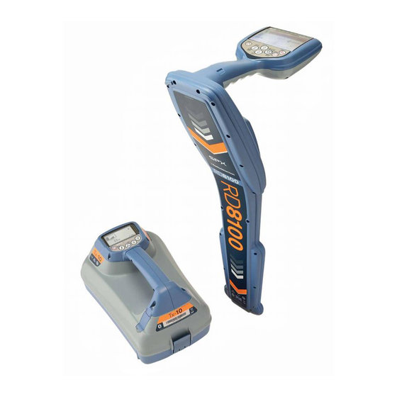
- Page 1 RD8100 ™ Precision Multifunction Cable & Pipe Locator Operation manual 90/RD8100-OPMAN-ENG/03...
-
Page 2: Table Of Contents
Table of Contents Section 1 - Preface ........2 Section 8 - Using accessories ....30 1.1 Important notices ......... 2 8.1 About accessories ........30 1.2 Compliance ..........3 8.2 Headphones ..........30 1.3 Intellectual property ........3 8.3 Locator clamps .......... 30 Section 2 - Introduction ....... -
Page 3: Section 1 - Preface
Section 1 - Preface Before you begin WARNING! Direct connection to live conductors is POTENTIALLY LETHAL. Direct connections to live Thank you for your interest in Radiodetection’s conductors should be attempted by fully qualified RD8100™ cable and pipe locator. personnel only using the relevant products that allow connections to energized lines. -
Page 4: Compliance
© 2015 Radiodetection Ltd. All rights reserved. Wireless technology compliance Radiodetection is a subsidiary of SPX Corporation. SPX, the green “>” and “X” are trademarks of SPX Use of iLOC wireless technology where applicable may Corporation, Inc. Radiodetection and RD8100 are be subject to national telecommunication regulations. -
Page 5: Section 2 - Introduction
Section 2 - Introduction 2.1 About this manual 2.4 Manual outline This manual provides cable pipe survey Section 1 includes an overview of safety procedures and professionals with comprehensive operating instructions notices. Review them before moving on to Section 2 and for the RD8100 locator and transmitter system. -
Page 6: Training
authorized accessories only. Incompatible Do not attempt to open or dismantle any part of this accessories may damage the equipment or give equipment unless directed specifically by this manual. inaccurate readings. Doing so may render the equipment faulty and may void the manufacturer’s warranty. - Page 7 GPS active, seeking satellite lock GPS satellite lock acquired 3 – 5 satellites fixed 6 – 8 satellites fixed 9 – 11 satellites fixed 12 or more satellites fixed Figure 3.1: RD8100 Locator © 2015 Radiodetection Ltd...
-
Page 8: Section 3 - System Overview
Section 3 - System overview 20 Gain and Log number: Displays the log number 3.1 RD8100 locator momentarily after a survey measurement is saved to memory Locator features 21 Volume icon: Displays the volume level Keypad 22 Current Direction arrows LCD with auto backlight 23 Radio Mode: Indicates when Radio Mode is active Speaker... - Page 9 Figure 3.2 Tx Transmitter © 2015 Radiodetection Ltd...
-
Page 10: Tx-1, Tx-5 And Tx-10 Transmitters
23 Bluetooth icon (Bluetooth Tx models): Indicates 3.2 Tx-1, Tx-5 and Tx-10 status of Bluetooth connection. A flashing icon transmitters means pairing is in progress Transmitter features Keypad Removable accessory tray D-cells battery holder Optional Lithium-Ion rechargeable battery pack Bluetooth module antenna (model dependent) Figure 3.3 Tx-1, Tx-5 and Tx-10 signal transmitters Transmitter keypad Power key... - Page 11 Navigating the locator menu Navigating the transmitter menu Press the key to enter the menu Press the key to enter the menu Use the keys to scroll through the menu Use the keys to scroll through the menu options options key to enter the option’s submenu.
-
Page 12: Section 4 - Operation
Section 4 - Operation 4.1 First use On the transmitter: To fit the D-cell batteries in the transmitter, unlatch the Power options accessory tray. The battery compartment (see figure 3.2) is located underneath the transmitter body. Use the RD8100 systems are shipped as standard configured to turnkey to unlatch the battery compartment. - Page 13 Figure 4.4 Press the retaining latch inwards Figure 4.7 Connecting the Li Ion lead Rotate the battery pack away and up from the latch Repeat on the other side to release the battery pack NOTE: Fully charge your lithium-ion battery pack before completely then lift the battery pack away its first use Transmitter battery pack:...
-
Page 14: Power On / Off
Charging the lithium ion packs WARNING! Do not heat the rechargeable battery pack above 60°C (140°F) as this will damage the battery’s thermal fuses. Locator Li-Ion battery pack To recharge the locator battery pack, connect the battery charger to the DC input connector on the front of the battery pack. -
Page 15: Keypad Actions & Shortcuts
Transmitter key actions 4.3 Keypad actions & shortcuts Short press Long press Locator key actions Enter the menu Switch power off Short press Long press Scroll through locate Enter the menu Switch power off frequencies from low to high Scroll through locate In active locating: Take voltage and Take voltage and... -
Page 16: System Setup
4.5 System setup Press the key to accept your selection and return to the main menu The RD8100 locator and transmitter settings can be Press the key to return to the main operation accessed via the menu. Once in the menu it is possible screen to change settings according to your personal preferences... -
Page 17: Dynamic Overload Protection
4.7 TruDepth™ measurement Press the key (on the locator) or the key (on the transmitter) to enter the FREQ menu All RD81 00 locators use TruDepth™ to measure depth Scroll through the frequency options using the automatically when a good quality reading can be keys assured. -
Page 18: Bluetooth Wireless
The transmitter’s LCD backlight is activated whenever Scroll to the OPT F menu using the keys you press a key. The backlight will automatically switch off after a few minutes. Press the key to enter the OPT F menu Scroll through using the keys until START is displayed 4.11 Bluetooth wireless... -
Page 19: Transmitter Eco Mode
To enable boost: Impedance & voltage measurements First configure the boost duration using the 1. Connect the Direct Connection leads to the utility procedure above and switch on the transmitter. Press and hold the key until BOOST appears on 2. Hold down the key until MEAS is displayed and the transmitter LCD the measuring icon is activated. -
Page 20: Usage-Logging
Note: When SBAS is ON the GPS system may take 4.18 Usage-Logging longer to lock RD8100 logging and GPS locator models feature a Internal GNSS ‘GPS’ powerful data logging system which records all the instrument’s critical parameters (including GPS position, RD8100 GPS models have an internal GNSS module. -
Page 21: Section 5 - Locating Cables And Pipes
Section 5 - Locating cables and pipes This section introduces the principals and techniques of locating buried cable and pipe utilities with the RD8100 system. For more information on the theory of cable and pipe location, refer to ABC & XYZ of locating buried pipes and cables, which is available to download from www.radiodetection.com Contact your local Radiodetection sales office or... -
Page 22: Antenna Modes
other technicians working on the line of the hazard and To manually select a transmitter output guard exposed conductors to prevent accidental contact. frequency: Press the key to cycle through available Induction frequencies In this mode of operation the transmitter is placed on the To change frequencies using iLOC, refer to Section 13. - Page 23 Peak+™ mode Guidance mode Peak+™ mode combines the accuracy of the Peak Guidance mode offers good performance in distorted bargraph with a choice of Guidance or Null directional fields and provides three indicators to guide the user arrows. towards the target line. Guidance arrows provide visual indication of the The Left and Right Proportional Arrows become shorter direction to the target utility, and are designed to get you...
-
Page 24: Compass
NOTE: it may be necessary to adjust the sensitivity level Null mode throughout the pinpointing to keep the bar graph on Null mode is used to verify a locate signal in scale. environments with limited or no interference or distortion. Null mode gives a null response when it is directly over With the antenna perpendicular to the line, make the line. -
Page 25: Sweep And Search
Inductive search 5.6 Sweep and search An inductive search procedure is a more certain There are a number of techniques available for locating technique for locating unknown lines. This type of search unknown lines in an area. Using these techniques is requires a transmitter and locator and two people. -
Page 26: Section 6 - Depth And Current Readings
Section 6 - Depth and current readings 6.1 TruDepth™ The RD8100 locator provides automatic depth of buried cables, pipes and sondes and when the locator is correctly orientated above the target line or sonde. Current readings are also displayed simultaneously if the locator is orientated correctly (feature not available in sonde or passive frequency modes). -
Page 27: Current Readings
conditions are suitable so the following techniques Method 2 should be used to check critical readings: Apply a signal to a cable or pipe of known depth. Check that the route of the line is straight for at least Locate the cable or pipe;... - Page 28 The line with the highest current measurement, rather Applying a transmitter signal than the line giving the strongest response, is the target The transmitter signal can be connected, clamped or line to which the transmitter signal has been connected. induced to the target line in the same way as the signal Measuring current provides useful information about the for line tracing is applied.
-
Page 29: Section 7 - Locating Techniques
Section 7 - Locating techniques Return signal flowing on another line. Use a double- 7.1 Identifying target utilities ended connection to by-pass the ground return if possible Induction Choose a signal application point where the line is If several conductors are running in parallel, and it is not furthest from other lines and not in a congested possible to connect a transmitter, each line may be area... -
Page 30: Signal & Ground Connection
Finding a good ground point 7.2 Signal & ground connection When using a Direct Connection, it is important to get Manhole covers the best possible grounding for the transmitter. This provides the lowest resistance ground path and the best Sometimes when locating, it is not possible to insert the output signal. -
Page 31: Section 8 - Using Accessories
Section 8 - Using accessories 8.1 About accessories When to use clamps Both the transmitter and locator are compatible with a Clamps can be used where: wide range of accessories. Several cables or pipes run in close proximity to When an accessory is connected, the locator or each other. -
Page 32: Transmitter Clamps
WARNING! Before applying or removing the clamp around a power cable, ensure that the clamp is connected to the transmitter at all times. The clamp may buzz or vibrate if it is placed around a power cable that has significant net current flow. This is normal and does not harm the equipment. -
Page 33: Sondes
NOTE: It is not necessary to make a ground connection Radiodetection locator can then be used to locate the from the transmitter when using the clamp. sonde Transmitter clamp range Choosing a suitable sonde Although transmitter and locator clamps look the same, Radiodetection offers a wide range of sonde to suit most applications: From the ¼”... - Page 34 The sonde radiates a Peak field from the center of its should then be directly above the sonde with the axis with a ghost signal at each end of the Peak. Move antenna in line with it. Mark the position of the sonde the locator a little way behind and then in front of the axis and its direction.
-
Page 35: Stethoscopes
Small stethoscope antenna WARNING: Failure to follow the Tx-5 or Tx-10 instructions above may result in the tip of the FlexiTrace The small stethoscope antenna has a 25mm (2”) becoming too hot to touch, resulting in risk of personal concave head at the end of a 2m (6½ ft) lead. The small injury and damage to the equipment. - Page 36 the line. The transmitting signal should be applied by Direct Connection with the strongest possible signal and at the frequency that the submersible antenna is calibrated to. Make a ground connection about 50m (160ft) from the transmitter. Test the quality of signal on the line before locating on the water.
-
Page 37: Section 9 - Fault-Finding
Section 9 - Fault-finding cable and clip the connector to the ground stake 9.1 About fault-finding ensuring that a positive connection is achieved RD8100PDL and PTL locators are capable of locating NOTE: Always connect the black connection lead to a cable to ground faults caused by damaged cable ground stake and not a water pipe or buried cable, as sheaths and can also be used to locate damage to... -
Page 38: How To Find A Fault
should be pointing away from the ground stake. If it is Take readings at the survey intervals determined by the not, make sure that the transmitter is connected correctly reference reading. To locate the cable or pipe while (red connector to the cable and black to the ground using the fault find signal during a Fault-Find survey, stake). -
Page 39: Section 10 - Current Direction (Cd)
Section 10 - Current Direction (CD) 10.1 Understanding CD Current Direction recognition is a feature that helps to positively identify a line at points distant from the application of the signal. It is highly desirable, if not essential, for positive identification of long distance lines. These lines can be traced and positively identified through congested areas or when running parallel to other lines. -
Page 40: Cd Reset
a CD reset may only be required every 20 kilometers (15 10.2 CD reset miles). About CD reset Performing a CD reset When you trace a signal on very long target lines, the You should perform a CD reset every time you select a transmitter signal gradually bleeds into the ground by CD frequency. -
Page 41: Section 11 - Survey Measurements
Section 11 - Survey measurements RD8100 locator models are capable of recording up to NOTE: A flashing depth and / or current reading display 10000 survey measurement records to internal memory. means that the measurement is poor and should be When a measurement is taken and saved, the RD8100 taken again. -
Page 42: Surveycert
11.4 SurveyCERT™+ Press the key to enter the menu Scroll to the DATA menu using the keys Stored data can be transferred wirelessly to a compatible running Radiodetection’s Press the key to enter the DATA menu SurveyCERT+ app or a PDA compatible application. Scroll up or down to the SEND option The Radiodetection SurveyCERT+ PDA app can read survey data for post survey analysis. -
Page 43: Section 12 - Bluetooth Wireless Connections
Section 12 - Bluetooth wireless connections RD8100 locators feature a Bluetooth wireless module, as standard, providing the ability to connect to compatible devices such as iLOC enabled transmitters (Tx-5B or Tx-10B), or handheld devices running a compatible application. 12.3 Pairing to a transmitter NOTE: The RD8100 locator wireless features may be subject to national and or local regulations. -
Page 44: Pairing To A Pda Or Pc
12.4 Pairing to a PDA or PC 12.5 Bluetooth Protocol RD8100 locators can transmit survey measurements to Connection requirements a paired PDA device running a compatible program. Any RD8100 locator To set the locator to work with Radiodetection’s SurveyCERT+ application, you need to set the data ... -
Page 45: Troubleshooting
11 Re-pair your devices as described in section 4.4 12.7 Troubleshooting Bluetooth error codes Successful wireless communication depends on a number of factors including: battery life, electromagnetic If an error occurs when attempting to perform any interference, device memory and physical obstructions. Bluetooth command using the locator to the transmitter Ensure that the RD8100 locator, transmitter and any or the locator to a PC or PDA, the LCD will display a code... -
Page 46: Section 13 - Iloc
Section 13 - iLOC™ iLOC is a standard feature of all RD8100 locator models. 13.2 iLOC functions iLOC lets you control a Bluetooth transmitter (Tx-5B or Tx-10B models) remotely using your locator. With iLOC you can adjust the output frequency, power settings and Changing frequencies use SideStep. -
Page 47: Sidestep
Once you have selected the mode you want, press key to confirm Press and hold the key to select the new setting and exit the menu Press the key once to send the settings to the transmitter NOTE: Once you have stored the transmitter power setting in the locator, the locator will change the transmitter to that setting when you change the frequency with the locator. -
Page 48: Section 14 - Appendices
Section 14 - Appendices Regularly check your locator for correct operation using 14.1 Care and maintenance eCert (see section 14.6) and the on-board Self-Test. The RD8100 locator and transmitter are robust, durable NOTE: Service by non-approved service centers or and weatherproof. However you can extend your operators may void the manufacturer’s warranty. -
Page 49: Warranty And Extended Warranty
If you have problem in obtaining and installing the RD Manager software you can also register your product(s) NOTE: eCert is not presently available for transmitters. by sending an e-mail to rd-support@spx.com. You will need to provide the following details: 14.7 Time and date error... -
Page 50: List Of Supported Accessories
14.8 List of supported accessories Locator Accessories High Gain Stethoscope 10/RX-STETHOSCOPE-HG Small Stethoscope 10/RX-STETHOSCOPE-S Large Stethoscope 10/RX-STETHOSCOPE-L CD Stethoscope 10/RX-CD-STETHOSCOPE 640 / 512Hz Submersible DD Antenna (10m Cable) 10/RX-SUBANTENNA-640 8kHz Submersible DD Antenna (10m Cable) 10/RX-SUBANTENNA-8K Headphones 10/RX-HEADPHONES A-Frame (includes A-Frame Lead) 10/RX-AFRAME A-Frame Bag 10/RX-AFRAME-BAG... - Page 51 Earth Reel 10/TX-EARTHLEAD Mains power AC transformer to 12V DC 10/TX-MPSU-XX XX= US, UK, EU, AU, CN Tx Direct Connection Lead 10/TX-DC-LEAD Tx DC Lead, Insulated Plug/Socket 10/TX-DC-LEAD-INS Earth Stake 10/TX-EARTHSTAKE Transmitter Connection Kit Contains Earth Reel, Earth Stake, Connection Leads and Magnet 10/TX-CONNECTION-KIT Signal Clamp Extension Rod...
- Page 52 10/SONDE-BENDI- Pack of 5 AA batteries BATPACK FlexiTrace 50m (Tx powered pushrod transmitter) 10/TRACE50-XX FlexiTrace 80m (Tx powered pushrod transmitter) 10/TRACE80-XX XX = D, F, GB, NL 4.5mm 50m Flexrod 10/FLEXRODF50-4.5 4.5mm 80m Flexrod 10/FLEXRODF80-4.5 6.7mm 50m Flexrod 10/FLEXRODF50-7 6.7mm 100m Flexrod 10/FLEXRODF100-7 6.7mm 150m Flexrod 10/FLEXRODF150-7...
- Page 53 10/TX-MCHARGER- LION-XX Li-Ion mains charger Replace XX with US, UK, EU or CN Replacement Li-Ion battery pack 10/TX-BATPACK-LION Transport and Storage Accessories Soft carry bag 10/LOCATORBAG Flight case 10/RD7K8KCASE Hard case 10/RD7K8KCASE-USA Miscellaneous Safety equipment Warning triangle 10/WARNING-TRIANGLE Calibration Certificates, Remote Calibration and PC Software Locator Calibration Certificate, per unit 97/RX-CALCERT (request with initial locator order)
- Page 54 Tel: +61 (0) 2 9707 3222 rd.sales.au@spx.com www.radiodetection.com Copyright © 2017 Radiodetection Ltd. All rights reserved. Radiodetection is a subsidiary of SPX Corporation. Radiodetection, and RD8100 are registered trademarks of Radiodetection in the United States and/or other countries. Trademarks and Notices. The following are trademarks of Radiodetection: RD8100, eCert, iLOC, TruDepth, SideStep, SideStepauto, RD Manager, Peak+, SurveyCERT, StrikeAlert, CALSafe, Current Direction and Power Filters.
Need help?
Do you have a question about the RADIODETECTION RD8100 and is the answer not in the manual?
Questions and answers