
Subscribe to Our Youtube Channel
Related Manuals for SPX Marley LW032 B Series


Summary of Contents for SPX Marley LW032 B Series
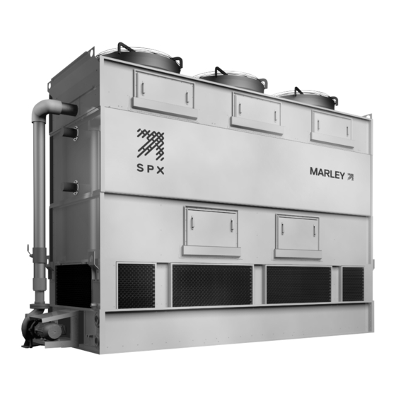
- Page 1 u s e r m a n u a l LW fluid cooler I N STA L L AT I O N - O P E R AT I O N - M A I N T E N A N C E Z1047819_C ISSUED 4/2019 READ AND UNDERSTAND THIS MANUAL PRIOR TO OPERATING OR SERVICING THIS PRODUCT...
-
Page 2: Table Of Contents
contents This manual contains vital information for the proper installation Note and operation of your fluid cooler. Carefully read the manual before installation or operation of the fluid cooler and follow all instruc- tions. Save this manual for future reference. Overview ........................3 Safety First........................3 Location .........................4... -
Page 3: Overview
Any such deviation, change or modification shall be the responsibility of the party or parties making such deviation, change or modification. SPX Cool- ing Technologies, Inc. expressly disclaims all liability for any such deviation, change or modification. -
Page 4: Location
Those are only some of the safety issues that may arise in the design process. SPX strongly recommends that you consult a safety engi- neer to be sure that all safety considerations have been addressed. Location Space available around the fluid cooler should be as generous as possible to promote ease of maintenance and to permit freedom of airflow into and through the fluid cooler. -
Page 5: Hoisting
receiving and hoisting Hoisting All LW fluid cooler models use reinforced hoisting clips located near the air inlet (bottom section) of the equipment for overhead lifting and handling of assembled shipping modules. A spreader bar should always be used at the top of the unit to help balance the load and prevent damage to the top section —... -
Page 6: Installation
installation Installation These installation instructions are intended to help you prepare Note before your fluid cooler arrives. If discrepancies exist between these instructions and those shipped with the fluid cooler, the instructions shipped with the fluid cooler will govern. 1. Prior to placement of the fluid cooler, confirm that the supporting platform is level, and that the anchor bolt holes are correctly located in accordance with Marley drawings. -
Page 7: Control Panel
Connect electrical supply wiring to main control panel in accordance with wiring diagram(s) and instructions included with control panel. For maintenance/safety purposes, SPX recommends a lockout type Warning disconnect switch for all mechanical equipment. Branch circuit protection must be provided for control panels and must meet or exceed all NEC and local codes. -
Page 8: Mechanical Equipment
operation also be incorporated into the main control panel. Basin heaters and electric water level packages, when selected, are contained within separate panels, but are wired to the main control panel to provide a single point power con- nection for power supply. Mechanical Equipment Always use caution when working near electrical and mechanical Warning... - Page 9 operation The water conditions during initial fluid cooler operation are crucial in pre- venting premature corrosion of galvanized steel (white rust). For at least the first eight weeks of operation, pH should be controlled between 6.5 and 8.0 with hardness and alkalinity levels between 100 and 300 ppm (expressed as CaCO 2.
-
Page 10: Operation
operation If the fluid cooler has been in operation and then shut down for a duration of time and not drained, perform one of the two previous biocidal treatment programs directly to the recirculating water storage vessel (collection basin, drain down tank, etc.) without circulating stagnant water over the coil(s) or operating the fan(s). -
Page 11: Dry Operation
operation fluid flow rate will cause the cold process fluid temperature to decrease slightly. However, at a given heat load (see formula above), process fluid flow reductions also cause an increase in the incoming hot process fluid temperature and thermal range. 4. -
Page 12: Freezing Weather Operation
operation Freezing Weather Operation During operation in subfreezing weather, the opportunity exists for ice to form in the colder regions of the fluid cooler. Primary concerns are to protect the heat transfer coil from freezing and prevent the formation of destructive ice on the fluid cooler air inlet and louvers. - Page 13 operation Basin heaters systems will not prevent the coil from freezing. Unless Caution some means of freeze prevention is incorporated into your system, the fluid cooler basin and exposed pipework should be drained at the beginning of each freezing weather shutdown period. If fluid cooler basin is drained, verify that all basin heaters have been Note shut off either by automatic cutoff or disconnect switch.
-
Page 14: Water Quality And Blowdown
operation Water Quality and Blowdown Maintaining Water Quality: Galvanized steel structural and casing components used in LW fluid coolers have been galvanized with a heavy zinc coating averaging 2.0 mils in thick- ness. Other materials used (PVC fill, drift eliminators, and louvers, aluminum fans, etc.) are selected to offer maximum service life in a “normal”... - Page 15 operation Blowdown: Evaporative heat exchange equipment functions by continuously causing a portion of the water circulated over the heat transfer media to evaporate. Although the water lost by evaporation is replenished by the makeup system, it exits the fluid cooler as pure water—leaving behind its burden of dissolved solids to concentrate in the remaining water.
-
Page 16: Fluid Cooler Inspection And Maintenance
maintenance Fluid Cooler Inspection and Maintenance Microorganisms including Legionella bacteria can exist in premise Warning plumbing including fluid coolers. The development of an effective water management plan (WMP) and implementation of maintenance procedures are essential to prevent the presence, dissemination and amplification of Legionella bacteria and other waterborne con- taminants throughout premise plumbing. -
Page 17: Access Doors
maintenance loosen the tap screws securing the frame in place and pull the frame away from the fluid cooler. Louver frames are not always the same size; if more than one louver frame is removed, the original location should be noted. Collection basin floor has uneven surfaces and has the potential to Caution be slippery. -
Page 18: Drift Eliminator Removal And Replacement
maintenance Drift Eliminator Removal and Replacement: Eliminator edges can be very sharp and can cut skin if proper pro- Caution tection is not used. Always wear gloves and sleeves when handling eliminator packs. The drift eliminators may be removed for cleaning, replacement or access to the distribution system. -
Page 19: Routine Maintenance
maintenance Routine Maintenance: Included with the instruction packet are separate User Manuals on major op- erating components of the fluid cooler, and it is recommended that you read them thoroughly. Where discrepancies may exist, the separate User Manuals will take precedence. The following is recommended as a minimum routine of scheduled maintenance: Always shut off electrical power to the fluid cooler fan motor prior Warning... -
Page 20: Seasonal Shutdown Instructions
maintenance Observe operation of the float valve. Depress the operating lever to make sure that the valve is operating freely. Inspect the suction screen for plugging. Remove any debris that may have accumulated. Check for any buildup of silt on the floor of the collection basin. Flush and remove excessive buildup. -
Page 21: Long Term Storage Procedures
maintenance Long Term Storage Procedures Instructions for protection of non-operating equipment for more than 3 months. After installation of the fluid cooler and completion of the pre-startup instruc- tions, the operational availability of equipment will last for a maximum period of three months. - Page 22 Be sure to mention your fluid cooler serial number (from the fluid cooler name- plate) when ordering parts. Periodic maintenance You may wish to contract with SPX Cooling for regularly scheduled visits for the purpose of inspecting and reporting your fluid cooler’s condition, to make recommendations intended to prevent emergencies...
- Page 23 Numerous technical reports are published by SPX including more detailed information on a variety of evaporative heat rejection equipment operation and service topics. Your Marley sales representative will be happy to give you copies of these reports at no charge or you can download copies from our website at spxcooling.com.
- Page 24 SPX COOLING TECHNOLOGIES, INC. 7401 WEST 129 STREET Z1047819_C ISSUED 04/2019 OVERLAND PARK, KS 66213 USA ©2017-2019 SPX COOLING TECHNOLOGIES, INC ALL RIGHTS RESERVED. 913 664 7400 | spxcooling@spx.com In the interest of technological progress, all products are subject to design spxcooling.com...
Need help?
Do you have a question about the Marley LW032 B Series and is the answer not in the manual?
Questions and answers