
Related Manuals for Technibel SPA250X5TAA


Summary of Contents for Technibel SPA250X5TAA
- Page 1 TECHNICAL & SERVICE MANUAL SPA250X5TAA - GR250X5TAA SPA250X5TAA - GR250X7TAA SPA360X5TAA - GR360X7TAA SPA480X5TAA - GR480X7TAA SPLIT SYSTEM AIR CONDITIONER 0.8180.110.1 05/01...
-
Page 2: Table Of Contents
Table of Contents 1.SPECIFICATIONS…………………………………………………………………………… Unit Specifications…………………………………………………………………….. Major Component Specifications……………………………………………………. (A) Indoor Unit………………………………………………………………………..(B) Outdoor Unit………………………………………………………………………. 10 Other Component Specifications……………………………………………………. 13 (A) Indoor Unit………………………………………………………………………..13 (B) Outdoor Unit………………………………………………………………………. 14 Dimensional Data……………………………………………………………………... 15 (A) Indoor Unit………………………………………………………………………..15 (B) Outdoor Unit………………………………………………………………………. 17 Refrigerant Flow Diagram……………………………………………………………. 18 Operating Range………………………………………………………………………... -
Page 3: Specifications
1. SPECIFICATIONS 1-1 Unit Specifications MODEL No. Indoor Unit SPA250X5TAA Outdoor Unit GR250X5TAA POWER SOURCE 220 - 230 - 240 V / 1 Phase / 50 Hz PERFORMANCE Cooling Capacity BTU / h 25,000 Air circulation (Hi/Me/Lo) m3 / h... - Page 4 1. SPECIFICATIONS 1-1 Unit Specifications MODEL No. Indoor Unit SPA250X5TAA Outdoor Unit GR250X7TAA POWER SOURCE 380 - 400 - 415 V / 3N / 50 Hz PERFORMANCE Cooling Capacity BTU / h 25,000 Air circulation (Hi/Me/Lo) m3 / h 1,140/1,020/840...
- Page 5 1. SPECIFICATIONS 1-1 Unit Specifications MODEL No. Indoor Unit SPA360X5TAA Outdoor Unit GR360X7TAA POWER SOURCE 380 - 400 - 415 V / 3N / 50 Hz PERFORMANCE Cooling Capacity 10.6 BTU / h 36,000 Air circulation (Hi/Me/Lo) m3 / h 1,680/1,410/1,200 Moisture removal(High) Liters/h...
- Page 6 1. SPECIFICATIONS 1-1 Unit Specifications MODEL No. Indoor Unit SPA480X5TAA Outdoor Unit GR480X7TAA POWER SOURCE 380 - 400 - 415 V / 3N / 50 Hz PERFORMANCE Cooling Capacity BTU / h 47,800 Air circulation (Hi/Me/Lo) m3 / h 1,920/1,680/1,320 Moisture removal(High) Liters/h ELECTRICAL RATINGS...
-
Page 7: Major Component Specifications
1. SPECIFICATIONS 1-2 Major Component Specifications (A) Indoor Unit MODEL No. SPA250X5TAA Source 220 - 230 - 240 V / 1 phase / 50 Hz Remote controller (Accessory) RCS-5PN3E Controller P.C.B. Ass’y CR - X363GS Switch Ass’y – SW - X363GS Fan (Number…diameter) - Page 8 1. SPECIFICATIONS (A) Indoor Unit MODEL No. SPA360X5TAA Source 220 - 230 - 240 V / 1 phase / 50 Hz Remote controller (Accessory) RCS-5PN3E Controller P.C.B. Ass’y CR - X363GS Switch Ass’y – SW - X363GS Fan (Number…diameter) Centrifugal (4...ø150) Fan Motor Model…Nominal output KFG4Q - 101D5P...100 W...
- Page 9 1. SPECIFICATIONS Indoor Unit MODEL No. SPA480X5TAA Source 220 - 230 - 240 V / 1 phase / 50 Hz Remote controller (Accessory) RCS-5PN3E Controller P.C.B. Ass’y CR - X363GS Switch Ass’y – SW - X363GS Fan (Number…diameter) Centrifugal (4...ø150) Fan Motor Model…Nominal output KFG4Q - 101D5P...100 W...
-
Page 10: (B) Outdoor Unit
1. SPECIFICATIONS 1-2 Major Component Specifications (B) Outdoor Unit MODEL No. GR250X5TAA Source 220 - 230 - 240 V / 1 phase / 50 Hz Compressor Rotary (Hermetic) Model ... Code No. C - R221H5V Nominal output 2,200 Compressor oil 1,350 Ω... - Page 11 1. SPECIFICATIONS (B) Outdoor Unit MODEL No. GR250X7TAA Source 380 - 400 - 415 V / 3 phase / 50 Hz Compressor Rotary (Hermetic) Model … Code No. C - R224H8S Nominal output 2,200 Compressor oil 1,350 Ω Coil resistance (at 25°C) R - S : 5.54 , S - T : 5.54 , T - R : 5.54 Refrigerant amount at shipment...
- Page 12 1. SPECIFICATIONS (B) Outdoor Unit MODEL No. GR360X7TAA GR480X7TAA Source 380 - 400 - 415 V / 3 phase / 50 Hz Compressor Rotary (Hermetic) Scroll (Hermetic) Model...Code No. C - R243H8T ZR61KC - TFD - 522 Nominal output 2,400 3,750 Compressor oil 1,350...
-
Page 13: Other Component Specifications
1. SPECIFICATIONS 1-3 Other Component Specifications Indoor Unit MODEL No SPA250X5TAA SPA360X5TAA SPA480X5TAA Power Transformer ATR - I75B Rated Primary AC 230 V, 50 Hz Secondary 10.6 V, 0.93 A Capacity 9.86 VAC Ω 0.6 (at 20 °C) Coil resistance WHT –... -
Page 14: (B) Outdoor Unit
1. SPECIFICATIONS (B) Outdoor Unit MODEL No GR250X5TAA Compressor Motor Mgnetic Contactor FMCA - 1SZ607 Coil rated AC 220 - 240 V, 50 Hz Ω 828 ± 15 % Coil resistance (at 20°C) Contact rated V, A AC 440 V, 13A Auxiliary relay HH62S / 085 Coil rated... -
Page 15: Dimensional Data
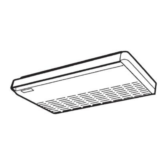
1. SPECIFICATIONS 1-4 Dimensional Data (A) Indoor Unit : 250, 360, 480 Type 250 type 360, 480 type 1270 1570 1048 1190 1490 Ref.gas line ø 15.88 ø19.05 Ref.liquid line ø6.35 ø9.52 Refrigerant gas line (Wide tube) Refrigerant liquid line (Narrow tube) Drain connection (20A, O.D. - Page 16 1. SPECIFICATIONS 1-4 Dimensional Data (B) Outdoor Unit: GR250X5TAA GR250X7TAA Dimension : mm Hole for anchor bolt (4-ø13) Refrigerant tube joint (narrow tube) Flare connection 1/4 in (6.35 mm) Refrigerant tube joint (wide tube) Flare connection 5/8 in (15.88 mm) Refrigerant tubing inlet Power supply inlet 0411_C_S...
-
Page 17: (B) Outdoor Unit
1. SPECIFICATIONS 1-4 Dimensional Data (B) Outdoor Unit: GR360X7TAA GR480X7TAA Dimension : mm Hole for anchor bolt (4-ø13) Refrigerant tube joint (narrow tube) Flare connection 3/8 in (9.52 mm) Refrigerant tube joint (wide tube) Flare connection 3/4 in (19.05 mm) Refrigerant tubing inlet Power supply inlet 0412_C_S... -
Page 18: Refrigerant Flow Diagram
1. SPECIFICATIONS 1-5 Refrigerant Flow Diagram Outdoor Unit : GR250X5TAA, GR250X7TAA Indoor Unit : SPA250X5TAA Wide tube service valve Strainer Capillary O. D. Accumulator 15.88 mm (5/8") High pressure switch Narrow tube service valve Strainer O. D. Sub-condenser 6.35 mm (1/4") - Page 19 1. SPECIFICATIONS Outdoor Unit : GR480X7TAA Indoor Unit : SPA480X5TAA Wide tube service valve O. D. Accumulator 19.05 mm (3/4") Narrow tube service valve Strainer O. D. Sub-condenser 9.52 mm (3/8") Insulation of Regrigerant Tubing IMPORTANT Insulator To prevent heat loss and wet floors due to Thickness: dripping of condensation, both the wide and Min.
-
Page 20: Operating Range
1. SPECIFICATIONS 1-6 Operating Range Temperature Indoor air intake temp. Outdoor air intake temp. 35 °C DB / 22.5 °C WB 52 °C DB Maximum 18 °C DB / 14 °C WB 19 °C DB Minimum – 20 –... -
Page 21: Cooling Capacity
1. SPECIFICATIONS 1-7 Cooling Capacity Indoor Unit :SPA250X5TAA Outdoor Unit : GR250X5TAA RATING CAPACITY : 7.3 kW AIR FLOW RATE : 1140 m EVAPORATOR CONDENSER ENT. TEMP. °C AMBIENT TEMP. 7.37 7.03 6.67 6.26 5.81 5.34 2.32 2.48 2.66 2.92 3.19... - Page 22 1. SPECIFICATIONS Indoor Unit :SPA250X5TAA Outdoor Unit : GR250X7TAA RATING CAPACITY : 7.3 kW AIR FLOW RATE : 1140 m EVAPORATOR CONDENSER ENT. TEMP. °C AMBIENT TEMP. 7.37 7.03 6.67 6.26 5.81 5.34 2.03 2.17 2.33 2.49 2.67 2.83 5.81 5.34...
- Page 23 1. SPECIFICATIONS Indoor Unit :SPA360X5TAA Outdoor Unit : GR360X7TAA RATING CAPACITY : 10.6 kW AIR FLOW RATE : 1680 m EVAPORATOR CONDENSER ENT. TEMP. °C AMBIENT TEMP. 10.7 10.21 9.69 9.08 8.44 7.76 2.11 2.25 2.42 2.63 2.86 3.07 9.08 8.44 7.76 10.7...
- Page 24 1. SPECIFICATIONS Indoor Unit :SPA480X5TAA Outdoor Unit : GR480X7TAA RATING CAPACITY : 14 kW AIR FLOW RATE : 1920 m EVAPORATOR CONDENSER ENT. TEMP. °C AMBIENT TEMP. 14.13 13.48 12.8 11.14 10.25 3.43 3.67 3.94 4.34 4.76 5.17 10.3 11.3 10.9 10.6 10.2...
-
Page 25: Noise Criterion Curves
1. SPECIFICATIONS 1-8 Noise Criterion Curves MODEL : GR250X5TAA - GR250X7TAA MODEL : SPA250X5TAA SOUND LEVEL : 53 dB(A), NC 45 SOUND LEVEL : HIGH 45 dB(A), NC 43 37 dB(A), NC 34 CONDITION : Distance 1m, Height 1m CONDITION... - Page 26 1. SPECIFICATIONS MODEL : SPA480X5TAA MODEL : GR480X7TAA SOUND LEVEL : HIGH 48 dB(A), NC 46 SOUND LEVEL : 56 dB(A), NC 47 40 dB(A), NC 36 CONDITION : Distance 1m, Under the unit 1m CONDITION : Distance 1 m, Height 1 m SOURCE : 220 - 230 - 240 V, 1 Phase, 50 Hz SOURCE...
-
Page 27: Air Throw Distance Chart
1. SPECIFICATIONS 1-9 Air Throw Distance Chart MODEL : SPA250X5TAA : 27 °C ROOM AIR TEMP. : 0 °C, 15 °C, 30 °C LOUVER ANGLE HORIZONTAL DISTANCE (m) 0˚ 15˚ 30˚ MODEL : SPA360X5TAA : 27 °C ROOM AIR TEMP. -
Page 28: Processes And Functions
2. PROCESSES AND FUNCTIONS 2-1 Room Temperature Control The Unit adjusts room temperature by turning the outdoor unit’s compressor ON and OFF. This process is controlled by the thermostat located in the remote control unit. The figures on this and the next pages show how each part of the system performs when the room temperature changes and the thermostat activates the compressor to start (thermo ON) or stop (thermo OFF). -
Page 29: Freeze Prevention (Cooling)
2. PROCESSES AND FUNCTIONS 2-2 Freeze Prevention Freeze Prevention keeps the indoor heat exchange coil from freezing. Freezing reduces the efficiency of the unit, and frost buildup on the coil blocks cool air circulation from the indoor unit’s fan. FREEZE FREEZE PREVENTION PREVENTION... -
Page 30: Electrical Data
3. ELECTRICAL DATA 3-1 Electrical characteristics Indoor model : SPA250X5TAA Outdoor model : GR250X5TAA Indoor Unit Outdoor Unit Complete Unit Fan Motor Fan Motor Compressor Performance at 220 - 240 V / 1 phase / 50 Hz 220 - 240 V / 1 phase / 50 Hz 0.43 / 0.43... - Page 31 3. ELECTRICAL DATA Indoor model :SPA480X5TAA Outdoor model : GR480X7TAA Indoor Unit Outdoor Unit Complete Unit Fan Motor Fan Motor Compressor Performance at 220 - 240 V / 1 phase / 50 Hz 380 - 415 V / 3 phase / 50 Hz 0.95 / 0.98 1.51 / 1.56 7.66 / 8.19...
-
Page 32: Electric Wiring Diagrams / Schematic Diagrams
3. ELECTRICAL DATA 3-2 Electric Wiring Diagrams / Schematic Diagrams Indoor Unit SPA250X5TAA, SPA360X5TAA, SPA480X5TAA – 32 –... - Page 33 3. ELECTRICAL DATA SPA250X5TAA, SPA360X5TAA, SPA480X5TAA • Schematic Diagram CR-X363GS Controller 4P-1 4P-4 Coil 49FMI Room 4P-2 Symbols Description Symbols Description Indoor Fan Motor CR-X363GS Indoor Controller 49FMI Indoor Motor Thermal Protector Indicator Lamp Assy Capacitor Switch Assy Fuse Terminal Plate...
- Page 34 3. ELECTRICAL DATA 3-2 Electric Wiring Diagrams / Schematic Diagrams Outdoor Unit GR250X5TAA • Electric Wiring Diagram Terminal Plate Connector 2P (WHT) 63PH Earth Terminal – 34 –...
-
Page 35: (B) Outdoor Unit
3. ELECTRICAL DATA GR250X5TAA • Schematic Diagram 63PH Symbols Description Compressor motor Fan Motor Compressor Motor Magnetic Contactor 63PH High Pressure Switch Fan Speedcontrol Thermostat C1, 2 Capacitor Overload relay Auxiliary Relay Connector Terminal Plate – 35 –... - Page 36 3. ELECTRICAL DATA GR250X7TAA • Electric Wiring Diagram Relay Terminal Plate Connector 2P (WHT) 63PH Earth Connector Terminal 6P (WHT) – 36 –...
- Page 37 3. ELECTRICAL DATA GR250X7TAA • Schematic Diagram 63PH Symbols Description Compressor motor Fan Motor Compressor Motor Magnetic Contactor Compressor Motor Overcurrent Relay Compressor Motor Thermal Protector Negative Phase Relay 63PH High Pressure Switch Fan Speedcontrol Thermostat Capacitor Auxiliary Relay Connector Terminal Plate –...
- Page 38 3. ELECTRICAL DATA GR360X7TAA • Electric Wiring Diagram Relay Terminal Plate Connector 2P (WHT) 63PH Earth Terminal – 38 –...
- Page 39 3. ELECTRICAL DATA GR360X7TAA • Schematic Diagram 63PH Symbols Description Compressor motor FM1, 2 Fan Motor Compressor Motor Magnetic Contactor Compressor Motor Overcurrent Relay Compressor Motor Thermal Protector Negative Phase Relay 63PH High Pressure Switch Fan Speedcontrol Thermostat C1, 2 Capacitor 1Y, 2Y Auxiliary Relay...
- Page 40 3. ELECTRICAL DATA GR480X7TAA • Electric Wiring Diagram Relay Terminal Plate Connector 2P (WHT) 63PH Earth Terminal – 40 –...
- Page 41 3. ELECTRICAL DATA GR480X7TAA • Schematic Diagram 63PH Symbols Description Compressor motor FM1, 2 Fan Motor Compressor Motor Magnetic Contactor Compressor Motor Overcurrent Relay Negative Phase Relay 63PH High Pressure Switch Fan Speedcontrol Thermostat C1, 2 Capacitor 1Y, 2Y Auxiliary Relay Connector Terminal Plate –...
-
Page 42: Service Procedures
4. SERVICE PROCEDURES 4-1 Trobleshooting (1) Check before and after Troubleshooting Many problems may happen because of wiring or power supply problems, so you should check these areas first. Problems here can cause false results in some of the other tests, and so should be corrected first. - Page 43 4. SERVICE PROCEDURES Air conditioner does not operate 1 1 1 1 1 Circuit breaker trips (or fuse blows). (a) When the circuit breaker is set to ON, it is tripped soon. • There is a possibility of ground fault. •...
- Page 44 4. SERVICE PROCEDURES (b) Circuit breaker trips in several minutes after turning the air conditioner on. • There is a possibility of short circuit. • Check capacity of circuit Replace it with a breaker. suitable one. Is capacity of circuit (= larger capacity) breaker sufficient ? •...
- Page 45 4. SERVICE PROCEDURES C. Check “Operation selector” switch in the indoor unit. : In case of wireless remote control unit • Has “Operation selector” IND. LAMP Ass’y or P.C.B. switch been set to ON Ass’y in the indoor unit position ? is defective.
- Page 46 4. SERVICE PROCEDURES Check. auxiliary relay. (1Y or 2Y) • Check coil resistance of auxiliary relay. (1Y or 2Y) 0620_X_S Check indoor fan motor thermal protector (49FMI) • Disconnect the socket from 9P (WHT) connector. • Check the continuity between No. 8 and No.9 poles of the 9P socket.
- Page 47 4. SERVICE PROCEDURES Outdoor unit does not run. Check COOL/FAN selector switch in the remote control unit. • Is COOL/FAN selector switch Set to COOL. set to COOL ? 0623_X_S Check set temperature. Try to lower set temperature by Temperature setting button “COOLER”.
- Page 48 4. SERVICE PROCEDURES Check compressor motor thermal protector (49C) • Check compressor motor Is temperature of compressor thermal protector. (49C) abnormally high ? Refrigerant gas shortage. Charge refrigerant gas. Compressor is defective. 0626_X_S • Check compressor motor magnetic contactor. (52C) 0627_X_S (Only outdoor fan does not run.) D.
- Page 49 4. SERVICE PROCEDURES Indoor unit does not run. (Indoor fan and louver motor do not run. P.C.B. Ass’y is defective. 0630_X_S Some part does not operate. (1) Indoor fan does not run. Check fan casing Remove foreign for foreign matter matter or repair.
- Page 50 4. SERVICE PROCEDURES Outdoor fan does not run. • Check fan casing Remove foreign for foreign matter matter or repair. Fan cannot on the inside. be rotated. • Check fan rotation. Rotate the fan gently once or twice by hand. •...
- Page 51 4. SERVICE PROCEDURES Poor cooling Check installation position Change installation of remote control unit. position of remote • Does cool air from air condi- control unit. tioner reach remote control unit directly ? Insulate wide tube and • Is wide tube between indoor unit then execute taping with and outdoor unit insulated ? narrow tube.
- Page 52 4. SERVICE PROCEDURES (10) Excessive cooling. Set the temperature to higher value using • The set temperature is too low. temperature setting button of the remote control unit. • Is the remote control unit installed Change installation at a place where it can position of the remote detect the room temperature control unit.
-
Page 53: A Sensor Is Defective
4. SERVICE PROCEDURES 4-2 A Sensor is Defective. 1 1 1 1 1 Indoor (heat exchanger) coil temp. Sensor is defective. (a) Open (=No continuity in sensor) Compressor and outdoor fan repeat ON for 10 minutes and OFF for 6 minutes when sensor opens. -
Page 54: Checking The Electrical Components
4. SERVICE PROCEDURES 4-4 Checking the Electrical Components Earthed wire Measurement of Insulation Clip Resistance • The electrical insulation is acceptable when the Probe resistance exceeds 1 MΩ. Insulation tester 0638_X_S Power Supply Wires Clamp the earthed wire of the Power Supply wires Fig. - Page 55 4. SERVICE PROCEDURES Checking the Protective Devices • Disconnect the connector, which consists of P (plug) and S (socket) when you want to check the protective device. • Then check continuity among plug’s (and/or socket’s) terminal as in Fig. 46. •...
- Page 56 4. SERVICE PROCEDURES Checking the Electrical Parts Power transformer (TR1) ....Indoor unit *Measure the coil resistance. • Primary 220-240 V ; Measure the resistance between two WHT lead wire terminals of socket connected to power transformer. • Secondary 10.6V ; Measure the resistance between two BRN lead wires. Refer to “1–3–(A) Other component specifications”.
- Page 57 4. SERVICE PROCEDURES Fuse on indoor P.C.B. Ass’y • Remove the P.C.B. Ass’y from the electrical component box. Then pull out the fuse from the P.C.B. Ass’y. (Fig. 48) Fuses Indoor P.C.B. Ass’y 0644_X_S Fig. 48 • The check for continuity of the fuse by using the multimeter. (Fig. 49) Having continuity is acceptable.
Need help?
Do you have a question about the SPA250X5TAA and is the answer not in the manual?
Questions and answers