
Subscribe to Our Youtube Channel
Related Manuals for Clarke CS5500


Summary of Contents for Clarke CS5500
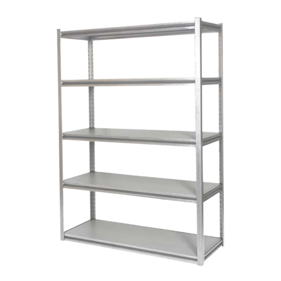
- Page 1 INDUSTRIAL BOLTLESS SHELVING Model Nos: CS5500, CS5500BP &CS5500RP Part Nos: 6600500, 6600600 & 6600605 ASSEMBLY INSTRUCTIONS GC11/11...
- Page 2 INTRODUCTION Thank you for purchasing this CLARKE Shelving Unit. Before attempting to use the product, it is essential that you read this manual thoroughly and carefully follow all instructions given. In doing so you will ensure the safety of yourself and that of others around you, and you can also look forward to the product giving you long and satisfactory service.
-
Page 3: Technical Specification
TECHNICAL SPECIFICATION r t s Please note that the details and specifications contained herein, are correct at the time of going to print. However, CLARKE International reserve the right to change specifications at any time without prior notice. LIST OF COMPONENTS When unpacking, check for damage and/or shortages etc. - Page 4 COMPONENTS Parts & Service: 020 8988 7400/E-mail:Parts@clarkeinternational.com or Service@clarkeinternational.com...
-
Page 5: General Safety Rules
GENERAL SAFETY RULES 1. Always maintain the equipment in good condition for the best/safest performance. 2. Never exceed the maximum load for these units. 3. Never use these units if they are damaged. 4. Always load small, stable items on the top shelves, heavier and bulky items should be stored on the lower shelves. - Page 6 5. Join the two end assemblies together by fitting two long beams (B) to the two bottom keyholes of the end assemblies. Ensure all beams are assembled in the upright position as shown in Fig 2. NOTE: Take care not to strike so hard as to damage the beams. Fig 2 6.
- Page 7 9. Assemble the top end assembly onto the Post Insert (F) as shown in Fig 4. 10. Repeat last two steps for the opposite top end assembly. 11. Add a short beam (C) to mid-section at the joint into the bottom keyholes of the top end assembly as shown in Fig 5.
- Page 8 Now the shelf decks can be laid between the beams as shown in Fig 8. 16. Insert the post caps (E) on top of the Angle Posts (A) as shown. Fig 8 OPTION 2 - ASSEMBLED AS A WORKBENCH 17. Create a bottom frame assembly by repeating steps 2 to 5. Fig 9 18.
- Page 9 19. Add two additional short beams and two long beams (B & C) to create a shelf at the required level.. Fig 10 20. Now assemble the second (add-on) shelving unit by joining the first short beam into the top of the angle posts. The second short beam should be installed at the 7th and 8th keyholes from the bottom of the posts as shown in Fig 10.
- Page 10 Fig 12 23. Lay the shelves (D) in between the beams as shown in Fig 12. 24. The two units can be used as free-standing shelves either individually or together, standing either in-line or at right angles. 25. To secure the frames together as shown in Fig 13, align the middle angle posts (A) together and align the indents on the Post Clips (G) with two keyholes of the back middle angle posts.
-
Page 11: Environmental Protection
COMPONENT PARTS ENVIRONMENTAL PROTECTION Do not dispose of this product or damaged parts with general household waste. All tools, accessories and packaging no longer required should be sorted, taken to a recycling centre and disposed of appropriately. Parts & Service: 020 8988 7400/E-mail:Parts@clarkeinternational.com or Service@clarkeinternational.com...
Need help?
Do you have a question about the CS5500 and is the answer not in the manual?
Questions and answers