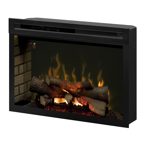
Dimplex PF3033 Service Manual
Hide thumbs
Also See for PF3033:
- Owner's manual (54 pages) ,
- Service manual (19 pages) ,
- Owner's manual (19 pages)
Table of Contents
Advertisement
IMPORTANT SAFETY INFORMATION: Always read this manual first before attempting to service this fireplace. For your
safety, always comply with all warnings and safety instructions contained in this manual to prevent personal injury or prop-
erty damage.
Service Manual
Model Number:
PF2325
PF3033
UL Part Number
690932XXXX
7400790100R03
Advertisement
Table of Contents

Related Manuals for Dimplex PF3033


Summary of Contents for Dimplex PF3033
- Page 1 Service Manual Model Number: PF2325 PF3033 UL Part Number 690932XXXX IMPORTANT SAFETY INFORMATION: Always read this manual first before attempting to service this fireplace. For your safety, always comply with all warnings and safety instructions contained in this manual to prevent personal injury or prop- erty damage.
-
Page 2: Table Of Contents
Exploded Parts Diagram - PF3033 Mod B-C . . . . . . . . . . . . . . . . . -
Page 3: Operation
Operation It is recommended that a straightened paperclip be used to press the button through the small hole. When the gWave controls are turned off, the green light will flash 4 times WARNING: This electric firebox must be properly in- before turning off and it will remain solid green when the stalled before it is used. - Page 4 The Boost can be set for a maximum of 20 minutes, Checking Software Level in 5 minute increments. The revision can be checked by press at the Multi-Fire XD™: Scrolls through the different same time. media theme color presets for the media, flame base and top lights. www.dimplex.com...
-
Page 5: Maintenance
CAUTION: If you need to continuously reset the heater, optimal performance is maintained. The grille can be disconnect power and call Dimplex customer service at cleaned by vacuuming off all dust and dirt. 1-888-DIMPLEX (1-888-346-7539). -
Page 6: Exploded Parts Diagram - Pf2325 Mod 0-A
20. Power Regulator Board ... . . PFRESISTORPCBRP Curved ....0441580300RP www.dimplex.com... -
Page 7: Exploded Parts Diagram - Pf2325 Mod B-C
Exploded Parts Diagram - PF2325 Mod B-C Replacement Parts - PF2325 Mod B-C: 13. Front Glass - Flat ..... . 1026770400RP Flicker Motor . -
Page 8: Exploded Parts Diagram - Pf3033 Mod 0-A
Exploded Parts Diagram - PF3033 Mod 0-A Replacement Parts - PF3033 Mod 0-A: 11. Front Glass ......1026770200RP Flicker Motor . -
Page 9: Exploded Parts Diagram - Pf3033 Mod B-C
Exploded Parts Diagram - PF3033 Mod B-C Replacement Parts - PF3033 Mod B-C: 12. Media Tray ......0441580200RP Flicker Motor . -
Page 10: Wiring Diagram
TOP LIGHT ASSY MOTOR T2 HEATER ASSEMBLY J7 GESTURE GESTURE ASSY FLICKER MOTOR NEUTRAL T7 MAIN TO GESTURE HARNESS J5 FLAME 1W DISPLAY J8 FLAME LED ASSY TYPE OF CONNECTIONS IS BASED ON TYPE OF FIREBOX DISPLAY BOARD ASSY www.dimplex.com... - Page 11 MOD B-C MAIN BOARD POWER SUPPLY LOGSET JUNCTION BOARD THERMAL CUT OUT MEDIA LED LIGHT ASSEMBLY RELAY BOARD HEATER ASSEMBLY FLAME BED LED ASSEMBLY (RGB) TOP LIGHT ASSY TOP LIGHT ASSY GESTURE ASSY FLICKER MOTOR FLAME LED LIGHT ASSEMBLY (1W)
-
Page 12: Main Control Board Replacement (Mod 0-A Units)
7. Properly orient and insert the new main control board. 8. Reassemble in the reverse order as above. Figure 2 Figure 3 Top Panel Mod 0-A gWave Assembly Top LED Light Heater Assembly Back Panel Main Control Board Flicker Motor Floating Display Flame LED Light Assembly Assembly www.dimplex.com... -
Page 13: Floating Display Assembly / Main Control Board Replacement (Mod B-C Units)
Floating Display Assembly / Main Control Power Supply Replacement (Mod B-C units Only) Board Replacement (Mod B-C units) Tools Required: Phillips Head Screwdriver CAUTION: If unit was operating prior to servicing allow Tools Required: Phillips Head Screwdriver at least 10 minutes for heating elements and top panel to CAUTION: If unit was operating prior to servicing allow cool off to avoid accidental burning of skin. -
Page 14: Heater Assembly Replacement
6. Disconnect the old assembly and connect the new as- Bottom Mounting Screws sembly. 7. Slide the assembly back into the unit. 8. Reassemble in the reverse order as above. www.dimplex.com... -
Page 15: Flame Led Light And Media Light Assembly Replacement
Flame LED Light and Media Light Top Light Replacement Assembly Replacement Tools Required: Phillips Head Screwdriver Needle Nose Pliers Tools Required: Phillips Head Screwdriver CAUTION: If unit was operating prior to servicing allow Small Adjustable Wrench at least 10 minutes for heating elements and top panel to CAUTION: If unit was operating prior to servicing allow cool off to avoid accidental burning of skin. -
Page 16: Power Cord Replacement
6. With needle nose pliers, grasp the power cord strain relief grommet from inside the back of the bottom panel and push while twisting to remove. 7. Install the new power cord. 8. Reassemble in the reverse order as above. www.dimplex.com... -
Page 17: Log Set Junction Board Replacement Mod 0-B
Log Set Junction Board Replacement Lower & Media LED Light Assembly Mod 0-B Replacement Tools Required: Phillips Head Screwdriver Tools Required: Phillips Head Screwdriver Needle Nose Pliers Needle Nose Pliers CAUTION: If unit was operating prior to servicing allow CAUTION: If unit was operating prior to servicing allow at least 10 minutes for heating elements and top panel to at least 10 minutes for heating elements and top panel to cool off to avoid accidental burning of skin. -
Page 18: Partially Reflective Glass Replacement
8. Install the power regulator board to the left connector on the new glass. Properly orient and install the new the main control board. (Figure 9) glass. 9. Reassemble the unit. 9. Reassemble in the reverse order as above. Figure 8 Figure 9 Power Regulator Board www.dimplex.com... -
Page 19: Troubleshooting Guide
Troubleshooting Guide PROBLEM CAUSE SOLUTION General Short in unit wiring. Trace wiring in unit. Circuit breaker trips or fuse Additional appliances may exceed the current rating of blows when unit is turned on Improper circuit current rating the circuit breaker or fuse. Plug unit into another outlet or install unit on a dedicated 15 amp circuit. - Page 20 Defective flicker motor Replace flicker motor DATE 2-OCT-14 23-FEB-15 4-JAN-16 3-JUL-19 1-888-346-7539 | www.dimplex.com In keeping with our policy of continuous product improvement, we reserve the right to make changes without notice. © 2019 Glen Dimplex Americas www.dimplex.com...
Need help?
Do you have a question about the PF3033 and is the answer not in the manual?
Questions and answers