Dimplex PF2325 Service Manual
Hide thumbs
Also See for PF2325:
- Owner's manual (54 pages) ,
- Service manual (15 pages) ,
- Owner's manual (18 pages)
Table of Contents
Advertisement
IMPORTANT SAFETY INFORMATION: Always read this manual first before attempting to service this fireplace. For your
safety, always comply with all warnings and safety instructions contained in this manual to prevent personal injury or prop-
erty damage.
Dimplex North America Limited
1367 Industrial Road Cambridge ON Canada N3H 4W3
1-888-346-7539 www.dimplex.com
In keeping with our policy of continuous product development, we reserve the right to make changes without notice.
© 2016 Dimplex North America Limited
Service Manual
Model Number:
PF2325
PF3033
UL Part Number
690932XXXX
REV
PCN
DATE
00
-
2-OCT-14
01
-
23-FEB-15
02
4-JAN-16
7400790100R02
Advertisement
Table of Contents

Related Manuals for Dimplex PF2325


Summary of Contents for Dimplex PF2325
- Page 1 Dimplex North America Limited 2-OCT-14 1367 Industrial Road Cambridge ON Canada N3H 4W3 23-FEB-15 1-888-346-7539 www.dimplex.com In keeping with our policy of continuous product development, we reserve the right to make changes without notice. 4-JAN-16 © 2016 Dimplex North America Limited 7400790100R02...
-
Page 2: Table Of Contents
Exploded Parts Diagram - PF2325 Mod 0-A . . . . . . . . . . . . . . . . . -
Page 3: Operation
OPERATION It is recommended that a straightened paperclip be used to press the button through the small hole. When the gWave controls are turned off, the green light will flash 4 times WARNING: This electric firebox must be properly in- before turning off and it will remain solid green when the stalled before it is used. - Page 4 The Boost can be set for a maximum of 20 minutes, Checking Software Level in 5 minute increments. The revision can be checked by press at the Multi-Fire XD™: Scrolls through the different same time. media theme color presets for the media, flame base and top lights. www.dimplex.com...
-
Page 5: Maintenance
CAUTION: If you need to continuously reset the heater, optimal performance is maintained. The grille can be disconnect power and call Dimplex customer service at cleaned by vacuuming off all dust and dirt. 1-888-DIMPLEX (1-888-346-7539). -
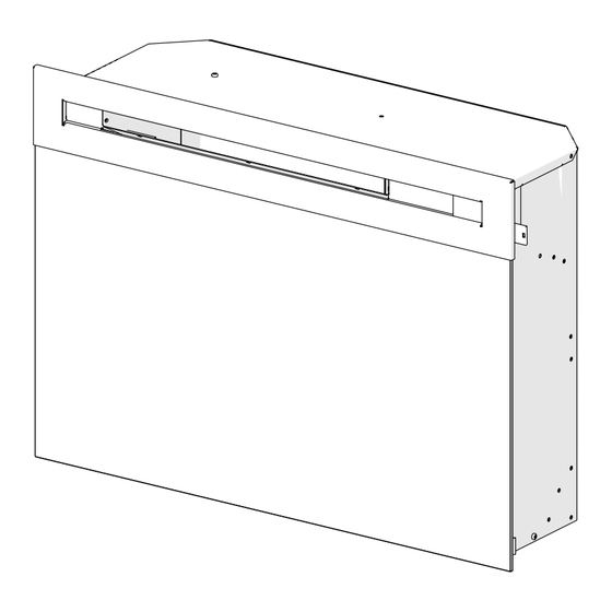
Page 6: Exploded Parts Diagram - Pf2325 Mod 0-A
EXPLODED PARTS DIAGRAM - PF2325 Mod 0-A Replacement Parts - PF2325 Mod 0-A: 11. Front Glass - Flat ..... . 1026770100RP Flicker Motor . -
Page 7: Exploded Parts Diagram - Pf2325 Mod B
EXPLODED PARTS DIAGRAM - PF2325 Mod B Replacement Parts - PF2325 Mod B: 13. Front Glass - Flat ..... . 1026770400RP Flicker Motor . -
Page 8: Exploded Parts Diagram - Pf3033 Mod 0-A
20. Power Regulator Board ... . . PFRESISTORPCBRP 10. Media Tray ......0441580200RP www.dimplex.com... -
Page 9: Exploded Parts Diagram - Pf3033 Mod B
EXPLODED PARTS DIAGRAM - PF3033 Mod B Replacement Parts - PF3033 Mod B: 12. Media Tray ......0441580200RP Flicker Motor . -
Page 10: Wiring Diagram
TOP LIGHT ASSY MOTOR T2 HEATER ASSEMBLY J7 GESTURE GESTURE ASSY FLICKER MOTOR NEUTRAL T7 MAIN TO GESTURE HARNESS J5 FLAME 1W DISPLAY J8 FLAME LED ASSY TYPE OF CONNECTIONS IS BASED ON TYPE OF FIREBOX DISPLAY BOARD ASSY www.dimplex.com... - Page 11 MOD B MAIN BOARD POWER SUPPLY LOGSET JUNCTION BOARD THERMAL CUT OUT MEDIA LED LIGHT ASSEMBLY RELAY BOARD HEATER ASSEMBLY FLAME BED LED ASSEMBLY (RGB) TOP LIGHT ASSY TOP LIGHT ASSY GESTURE ASSY FLICKER MOTOR FLAME LED LIGHT ASSEMBLY (1W)
-
Page 12: Main Control Board Replacement
Main Control Board Flicker Motor Floating Display Flame LED Light Assembly Assembly Figure 3 Mod B Top Panel Top LED Light Heater Assembly gWave Assembly Back Panel Power Board Relay Board Flicker Motor Floating Display Flame LED Light Assembly Assembly www.dimplex.com... -
Page 13: Floating Display Assembly / Main Control Board Replacement
3. Remove the loose media from the unit (if applicable). 8. Properly orient and insert the new floating display as- sembly. 4. Remove the 14 screws around the back panel of the firebox and the 3 along the middle of the panel (Figure 9. -
Page 14: Heater Assembly Replacement
10. Slide the flicker rod out of the snap-in bushing and to persons. remove. 1. Unplug the unit from power outlet. 11. Reassemble in the reverse order as above. www.dimplex.com... -
Page 15: Gwave Tm Assembly Replacement
10. Reassemble in the reverse order as above. Figure 7 MOD B Log set 1. Unplug the unit from power outlet. 2. Remove the firebox from the front of the mantel and remove front glass assembly (glass lifts off). CAUTION: Even though the glass is safety glass it may break if bumped, struck of dropped. -
Page 16: Power Supply Replacement
6. Remove the electrical connections from the electronics they are attached using magnets (if applicable). junction board, replace with new log set connections. 4. Gently place the unit its back to expose the bottom 7. Reassemble in the reverse order as above. www.dimplex.com... -
Page 17: Partially Reflective Glass Replacement
POWER REGULATOR BOARD of the unit. Remove the 4 screws from bottom and 2 screw form either side that secure the log set. INSTALLATION (Mod 0 units Only) 5. Lift the log set out of the unit, being careful not to strain Tools Required: Phillips Head Screwdriver the electronic cords. -
Page 18: Troubleshooting Guide
Media LED light assembly is not working Replace media LED light assembly not light up or is a different color Log set or Media bed lighting Defective main control board Replace the main control board comes on by itself www.dimplex.com... - Page 19 PROBLEM CAUSE SOLUTION Heater Heater is not turning on, but Improper operation Refer to Operation Section flame effect is still functioning Loose wiring Trace wiring in unit Defective main control board Replace the main control board Defective heater assembly Replace heater assembly Heater is turning off after a Improper operation Refer to Operation Section...
Need help?
Do you have a question about the PF2325 and is the answer not in the manual?
Questions and answers