Table of Contents
Advertisement
Quick Links
Advertisement
Table of Contents

Related Manuals for 2B Technologies OEM-106-H


Summary of Contents for 2B Technologies OEM-106-H
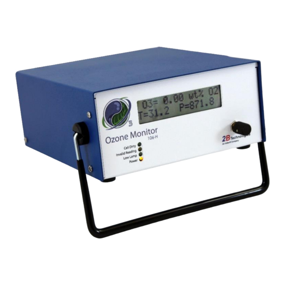
- Page 1 Ozone Monitor Technologies OPERATION MANUAL Models 106-H and OEM-106-H © Copyright 2018, 2B Technologies All rights reserved. Technical Support: https://twobtech.com/tech-support.html techsupport@twobtech.com +1(303)273-0559 Model 106-H Ozone Monitor Manual Rev. F-1...
-
Page 2: Table Of Contents
WARNINGS viii OZONE MONITOR INTRODUCTION Theory of Operation ......................... 1 Calibration and Zeroing Overview ................... 2 SPECIFICATIONS: Model 106-H and Model OEM-106-H OPERATION Shipping Box Contents ......................5 Operation of the Ozone Monitor ....................5 3.2.1 Powering the Instrument .................... 5 3.2.2... - Page 3 LABELED INSTRUMENT PHOTOS REPLACEMENT PARTS SERVICE LOG Appendix A: Using the 2B Technologies Display and Graphing Software Appendix B: Installation and Use of the USB Connection (for older versions of the Model 106 and/or Windows) Model 106-H Ozone Monitor Manual Rev. F-1...
-
Page 4: Identification Records
IDENTIFICATION RECORDS Record the following information for future reference: Unit serial number: ______________________________________ Warranty start date: _______________________________________ (date of receipt) Model 106-H Ozone Monitor Manual Rev. F-1... -
Page 5: Printing History
3.19, 3.20, and 4 regarding photodiode voltages and LED indicator light functionality; correction to serial line output voltage order in Section 3.12.3; updates of all web links; other minor edits. TRADEMARKS & PATENTS 2B Technologies, 2B Tech, 2B and Ozone Monitor are trademarks of 2B Technologies. CONFIDENTIALITY The information contained in this manual may be confidential and proprietary and is the property of 2B Technologies. -
Page 6: Warranty Statement
WARRANTY STATEMENT 2B Technologies, warrants its products against defects in materials and workmanship. 2B Technologies will, at its option, repair or replace products which prove to be defective. The warranty set forth is exclusive and no other warranty, whether written or oral, is expressed or implied. - Page 7 In no event shall 2B Technologies be liable for incidental or consequential damages in connection with or arising from the use of the Ozone Monitor manual and its accompanying related materials.
-
Page 8: Warnings
WARNING: Si este instrumento se usa de una forma no especificada por 2B If this instrument is used in a manner not specified by 2B Technologies, USA, the Technologies, USA, puede desactivarse la protección suministrada por el protection provided by the instrument may be impaired. -
Page 9: Ozone Monitor Introduction
OZONE MONITOR INTRODUCTION The 2B Technologies Model 106-H Ozone Monitor is designed to enable accurate measurements of ozone over a wide dynamic range extending from 0.01 percent by weight in oxygen (wt% O ) to an upper limit of 20 wt% O based on the well- established technique of absorption of ultraviolet light at 254 nm. -
Page 10: Calibration And Zeroing Overview
Reference Photodiode Temperature Hg Lamp Sample Sensor Photodiode Absorption Beamsplitter Cell Pressure Sensor Pressure Relief Sample Outlet and Scrubber Sample Inlet Figure 1.1. Schematic Diagram of the Model 106-H Ozone Monitor. When there is no ozone in the cell, a difference in light intensity at the reference and sample photodiodes can be expected, and it will cause a zero offset in the readings. -
Page 11: Specifications: Model 106-H And Model Oem-106-H
The user may perform the calibration (see Section 5), or return the instrument to 2B Technologies for calibration servicing. The zero may drift due to temperature change or chemical contamination of the absorption cell. - Page 12 Data Transfer Baud Rates 2400, 4800, 19200 Ozone Units , Ng m , vol%, wt% air, wt% O Temperature Units °C, °F, K Pressure Units mbar, torr, psi T and P Corrected Operating Temperature 0 to 50°C Range Operating Altitude Range 0 to 5 km Operating Pressure Limit 50 psig...
-
Page 13: Operation
(red) and negative (black) wires correctly. Batteries and battery chargers are available from 2B Technologies. A circuit breaker and diode are installed on the circuit board in case of an electrical short or incorrect battery attachment. If activated, the breaker will reset itself after a few minutes. -
Page 14: Connections To The Instrument
3.2.3 Connections to the Instrument Inlet tubing may be attached to the ¼ inch stainless steel Swagelok fitting on the back of the instrument. For the high concentrations of ozone typically used with the Model 106-H Ozone Monitor, stainless steel tubing is recommended. 3.2.4 Operating Parameters The Ozone Monitor has an internal pressure relief device that protects the instrument... -
Page 15: Menu
Menu The following diagram summarizes the complete instrument Menu. Main Menu Zero Admin D/T: 10:32:21 14/10/2009 2400 4800 19200 REL1 REL2 V_OUT Figure 3.1. Instrument Menu. Model 106-H Ozone Monitor Manual Rev. F-1... -
Page 16: Accessing The Main, Zero, And Admin Menus
Accessing the Main, Zero, and Admin Menus When first turned on, the instrument will first display the serial number and then start making measurements. As described in Section 3.2.1, allow a ~20-minute warmup period. The Main Menu is accessed using the black Select switch on the front panel of the instrument. -
Page 17: Data Averaging And Data Logging Using The Menu
Dat Menu Xmt Log End Click on End to make measurements without logging new data. This will return you to Select the Avg submenu and then select “2s” to make the Admin Menu. measurements without averaging. Click on to return to the Admin Menu and click ... -
Page 18: To Log Data
for example, where the most recent average value of ozone computed is 3.53 wt% O (note, because of character limits, only “wt” is displayed), the time of the measurement is 3:07 p.m. and the date is 19 July 2017. Note that entering the menu will interrupt the averaging interval that is in progress, and the averaging interval will start over when the menu is exited and measuring is resumed. -
Page 19: To Stop Logging Data
measured so far for inclusion in the next average to be displayed and logged. If 1-min averaging is used, this number will increment from 0 to 29; for 5-min averaging, the number will increment from 0 to 149; and for 1-hr averaging, it will increment from 0 to 1799. -
Page 20: To Change The Ozone, Temperature, And Pressure Measurement Units
the set time is entered, in this case by exiting all menus by clicking on , and resuming measurements. To Change the Ozone, Temperature, and Pressure Measurement Units From the Main / Admin / Cfg submenu, choose the Unt submenu: Unt Menu T/P O3 ... -
Page 21: To Change The Calibration Parameters
The Ozone Monitor will then exit the Menu and return to measuring ozone. 3.11 To Change the Calibration Parameters The instrument is calibrated at the factory where a slope (S) parameter is entered into the instrument’s memory. This preset calibration parameter is given in the instrument’s Birth Certificate and recorded on the calibration sticker inside the instrument. -
Page 22: Collecting Data Over The Usb Or Serial Port In Real Time
(reproduced and updated in this manual as Appendix B). 3.12.1 Data Acquisition Software Start your data acquisition software, preferably using the 2B Technologies Display and Graphing Software (available as a free download from the 2B Tech website at https://twobtech.com/docs/docs_software.htm). -
Page 23: Data Output
For the USB port, the baud rate setting in the data acquisition software must match the setting that the Model 106-H had at startup. If you wish to change the baud rate of the Model 106-H, change it in both the instrument and the software, and then reboot the instrument to begin taking data. -
Page 24: To Change The Baud Rate
Connect the USB or serial port of the instrument to your computer using the appropriate cable (see Section 3.12). Enable a data acquisition program on the computer such as the 2B Technologies Display and Graphing Software, which can be downloaded at: https://twobtech.com/docs/docs_software.htm Appendix A gives a summary of working with this display software. - Page 25 Start logging and write over existing logged data End logging and transmit logged data e End logging h Output serial data line header m Access serial menu If the letter m is sent as a command, menu> will be displayed in the terminal emulator window.
-
Page 26: Collecting Data From The Analog Output
3.16 Collecting Data from the Analog Output The data may be logged in real time using a data logger attached to the D9 connector on the back panel of the instrument using either a voltage or current recorder or data logger. -
Page 27: Lamp Test
With these settings, the relay will close (pass current) until the ozone concentration exceeds 5.10 wt% O . Above this concentration, the switch relay will open. The relay will not close again until the ozone concentration drops below 4.90 wt% O . -
Page 28: Led Indicator Lights
3.20 LED Indicator Lights Four indicator lights are on the left side of the front instrument panel: • The bottom light is a Power indicator. It indicates that there is power to the instrument and that the main circuit board is working properly. The normal state is ON. -
Page 29: Maintenance/Troubleshooting
~20,000 hours. It is recommended that the instrument we returned to 2B Technologies if any component fails. Alternatively, the user may install components at their own risk. In that case, please contact 2B Technologies for instructions. - Page 30 Cell Dirty LED is ON Absorption cell is dirty. Replace absorption cell, or during the auto-zero. return to 2B Tech for cell cleaning or replacement. Poor instrument zero. Zero the instrument. Display is blank or Bad connection of display Remove top cover and nonsense.
- Page 31 2B Technologies offers reasonably priced customer service for instrument repairs. The calibration service includes cleaning of the entire flow path with methanol, testing of all components for proper function and calibration against an IOA-traceable standard. The best way to contact us for service is to log a customer service ticket at https://twobtech.com/tech-support.html.
- Page 32 CALIBRATION Every analytical instrument is subject to some drift and variation in response, making it necessary to periodically check the calibration. Since the reliability of the data collected from any analytical instrument depends on the accuracy of the calibration, it is necessary to calibrate the instrument against a recognized standard such as the International Ozone Association (IOA) KI method.
- Page 33 5.2.2 Measurement of Zero Gas 1. Verify that the zero gas supply is on and the ozone generator is off. The same zero gas supply used in the ozone generator must be used in the zero gas measurement. 2. Allow the Model 106-H to sample zero gas until the response is stable. 3.
- Page 34 6. PERIODIC ZERO AND SPAN CHECKS To ensure the quality of the ozone monitor data, periodic zero and span checks can be performed by following the steps below: 1. A zero check is performed by sampling zero gas following the “Measurement of Zero Gas”...
- Page 35 LABELED INSTRUMENT PHOTOS Serial Port/ Relay Connectors Analog Out USB Connector 12 V Power In Pressure Relief Device (bottom) Power Switch Connector Pressure Microprocessor Sensor (top) Optical Bench Lamp Connector Pressure Relief Scrubber 5-V Regulator/ Cell Heater Connector Calibration Sticker Location Clock Battery (underneath Sample...
- Page 36 Select Switch Indicator LEDs Figure 7.2. Front Plate of the Model 106-H. Power Switch Serial Number Relay Connector 2 Outlet Inlet 12 V Power In Programming Serial Port/ Relay Jumper Connector Analog Out Connector 1 Figure 7.3. Back Panel of the Model 106-H. Model 106-H Ozone Monitor Manual Rev.
- Page 37 REPLACEMENT PARTS The following list includes those parts of the Model 106-H Ozone Monitor that are user serviceable. Please see the 2B Technologies website for a full and updated list of parts and pricing: https://twobtech.com/parts-online.html Part Number Description OZLAMPAS106H Lamp assembly...
- Page 38 SERVICE LOG 2B Tech Instrument Model #:____________ Serial #:_____________ Date/ Calibrated Cleaned Other Hours Lamp Model 106-H Ozone Monitor Manual Rev. F-1...
- Page 39 Date/ Calibrated Cleaned Other Hours Lamp Model 106-H Ozone Monitor Manual Rev. F-1...
- Page 40 .txt file and can optionally be saved to a .CSV file to be read in Excel. Saved data can be restored for later viewing and analyzing on the chart. By requesting an account with 2B Technologies, you can upload your data and view it on a Google Earth overlay.
- Page 41 setting. Note that for the USB port, the baud rate must match the baud rate of the Ozone Monitor at the Monitor’s startup. c) Parity: None d) Data Bits: 8 e) Stop Bits: One 4. Click Start button in the Instrument Data Capture section in the upper left corner of the main screen.
- Page 42 3. The data lines received from your instrument will be listed in a grid with the latest point at the top. 4. The header contains the device specific variables (e.g., Ozone, Cell Temp...). Log Number is always listed even if your instrument is not set to log. The Charts Tab 1.
- Page 43 1. After collecting data, click the Stop button in the Instrument Data Capture Section on the main screen. 2. A window will pop up to ask you if you would like to save to a CSV file as well. Click Yes. 3.
- Page 44 Appendix B: Installation and Use of the USB Connection (for older versions of the Model 106 and/or Windows) The following procedure describes how to install and use the USB connection for earlier versions of the Model 106-H (those having 1 relay rather than 2 relays) and/or for PC computers running earlier versions of Windows.
- Page 45 7. Navigate to folder where you unzipped the cdc_NTXP. 8. Select “Continue Anyway” when this window appears. 9. After a few seconds, the driver will be finished installing. Model 106-H Ozone Monitor Manual Rev. F-1...
- Page 46 Determine the Connection Port After installation is complete, determine which COM port the connection is using. This can be done by the following procedure. 1. If using Windows (XP,Vista,7), go to the control panel and select “System.” 2. Click on the “Hardware” tab. 3.
- Page 47 • When setting up your software or terminal emulator, choose the correct com port listed in the Device manager. • Use these baud rate settings: 2400, 8 bits; no parity; 1 stop bit. • Use 2B Technologies Display and Graphing Software (free download from https://twobtech.com/docs/docs_software.htm) or other software (such as HyperTerminal or Tera Term) to read measurement data from the Model 106.
Need help?
Do you have a question about the OEM-106-H and is the answer not in the manual?
Questions and answers