Table of Contents
Advertisement
Quick Links
Advertisement
Table of Contents
Troubleshooting

Related Manuals for 2B Technologies AQSync


Summary of Contents for 2B Technologies AQSync
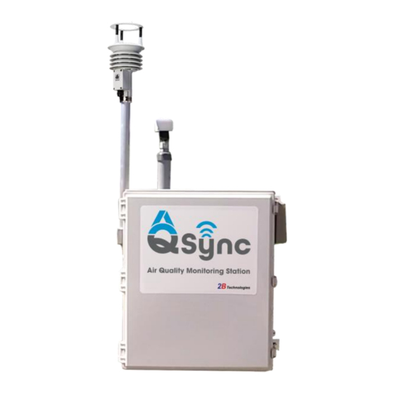
- Page 1 AQSync Air Quality Monitoring Station OPERATION MANUAL Model AQSync © Copyright 2024, 2B Technologies All rights reserved. Technical Support: https://2btech.io/support/ techsupport@2btech.io +1(303)273-0559 Model AQSync Air Quality Monitoring Station Manual Rev. C-1...
-
Page 2: Table Of Contents
A.1.2 Viewing and Acquiring Data with the AQSync ................. 3 A.1.2.1 Viewing AQSync Data via the Touchscreen .............. 3 A.1.2.2 Accessing AQSync Data via the Web and via USB ........... 3 A.1.2.3 Schematics of the AQSync’s Sample Flow and Data Flow ........4 A.2 This User Manual... - Page 3 E.4 CO and TVOCs Module Settings E.5 Weather Station Settings E.6 Particle Settings E.7 System Settings E.7.1 Upload Settings and Upload Status..................32 E.7.2 Wi-Fi Settings ........................33 E.7.3 Wi-Fi Access Point......................... 33 Model AQSync Air Quality Monitoring Station Manual Rev. C-1...
- Page 4 E.7.7 Cellular Status Page ......................35 E.7.8 About Page ..........................35 E.7.9 Static IP ..........................35 E.7.10 Modbus Server for Remote Operation of the AQSync ............35 E.7.11 Console ..........................36 E.7.12 Date and Time ........................36 F. Parameters and Graphing Screens F.1 Parameters...
-
Page 5: Identification Records
APPENDIX 4: Downloading Data Files over Wi-Fi APPENDIX 5: Recommended Maintenance and Calibration Schedule IDENTIFICATION RECORDS Record the following information for future reference: Unit serial number: ______________________________________ Warranty start date: _______________________________________ (date of receipt) Model AQSync Air Quality Monitoring Station Manual Rev. C-1... -
Page 6: Printing History
PRINTING HISTORY This manual covers the AQSync Air Quality Monitoring Station used for measurement of ozone (O ), nitric oxide (NO), nitrogen dioxide (NO ), carbon monoxide (CO), carbon dioxide (CO ) and particulate matter (PM , PM , PM ) in air. -
Page 7: Warranty Statement
2B Technologies warrants its products against defects in materials and workmanship. 2B Technologies will, at its option, repair or replace products that prove to be defective. The warranty set forth is exclusive and no other warranty, whether written or oral, is expressed or implied. -
Page 8: Conditions
In no event shall 2B Technologies be liable for incidental or consequential damages in connection with or arising from the use of the AQSync Air Quality Monitoring Station manual and its accompanying related materials. Warranty is valid only for the country designated on the 2B Technologies quote or invoice. -
Page 9: Warnings
WARNING: ATENCION: If this instrument is used in a manner not specified by 2B Technologies, Si este instrumento se usa de una forma no especificada por 2B USA, the protection provided by the instrument may be impaired. -
Page 10: Unpacking
UNPACKING Please read all the following information before attempting to install the AQSync Air Quality Monitoring Station. For assistance, please call 2B Technologies at (303)273- 0559. NOTE: Save the shipping carton and packing materials that came with the AQSync Air Quality Monitoring Station. -
Page 11: Overview
, PM ), carbon monoxide (CO), carbon dioxide (CO ), and VOCs. The AQSync can be installed at any location where line power is accessible—for example, on a light post or building, or at field sites. Customizable Choices for the AQSync:... -
Page 12: Summary Of The Aqsync Measurement Suite
0-360 degrees ±3° to 40 m/s direction MaxiMet GMX500 azimuth ±5° 40 to 60 Weather Station Some choices of the measurement suite are customizable and are specified at time of order. Model AQSync Air Quality Monitoring Station Manual Rev. C-1... -
Page 13: Viewing And Acquiring Data With The Aqsync
A.1.2.2 Accessing AQSync Data via the Web and via USB As shipped from the factory, the AQSync is configured so that data from its instruments and sensors are integrated and then transmitted via cellular or Wi-Fi to the web every 5 minutes. -
Page 14: Schematics Of The Aqsync's Sample Flow And Data Flow
A. Overview Schematics of the AQSync’s Sample Flow and Data Flow A.1.2.3 Model AQSync Air Quality Monitoring Station Manual Rev. C-1... -
Page 15: This User Manual
A. Overview This User Manual After gaining an overview of the AQSync through the description given in Section A.1 above, the user can find more detail in this manual’s 7 major sections: B. Assembly and Installation of the AQSync C. Quick Start: Initiating Measurements with the AQSync D. -
Page 16: Assembly And Installation Of The Aqsync
B. Assembly and Installation of the AQSync Assembly The weather station and particulate matter (PM) sampling inlet are detached from the AQSync for shipping to protect them from damage. Carefully unpack them and install them as shown here. B.1.1 Install PM Sampling Inlet Obtain the pieces of the Particulate Matter Sampling Inlet as shown below. - Page 17 A. Remove the plastic p-clamp that is securing the wires on the flange, taking care not to let the wires fall inside the AQSync. Plug in the wires on the core to these wire connections. Push the connected wires through the flange and into the AQSync now.
- Page 18 PM wires inside the AQSync. Use a zip tie or other means to tidy it up. Done! After installation, it is advisable to check for leaks. Use instructions in Section G.2.3. Connected wires Model AQSync Air Quality Monitoring Station Manual Rev. C-1...
-
Page 19: Install Weather Station
The weather station is a MaxiMet GMX500 Weather Station made by Gill Instruments Ltd. For more information about the installation of the wind sensor, please consult the manufacturer’s manual. Model AQSync Air Quality Monitoring Station Manual Rev. C-1... -
Page 20: Physical Installation
Please consult the user manual more information on using the compass. In the AQSync as shipped from the factory, the compass is turned off. Contact us if you wish to enable the compass. Model AQSync Air Quality Monitoring Station Manual Rev. C-1... -
Page 21: Dimensional Drawings
B. Assembly and Installation Dimensional Drawings Front View Back View Model AQSync Air Quality Monitoring Station Manual Rev. C-1... - Page 22 B. Assembly and Installation Side and Top Views Model AQSync Air Quality Monitoring Station Manual Rev. C-1...
-
Page 23: Quick Start: Initiating Measurements With The Aqsync
Below is a summary of the minimum steps for startup and use that are further described in this Section C. If the AQSync is deployed at a fixed installation site, step 6 will most likely not need to be repeated each time the AQSync is powered up. -
Page 24: Warmup And Battery Charging
Warmup and Battery Charging Each module of the AQSync requires a period of time to warm up, described below. Note that the green color of the bars on the left indicates that the modules are connected, not that they are warmed up. -
Page 25: Co/Gps (And Optional Vocs)
C.2.4 CO/GPS (and Optional VOCs) In a typical configuration of the AQSync, there are 2 identical CO sensors. The measured value of CO shown on the touchscreen and found in the data stream is the average of the 2 sensors. The CO sensors require an equilibration period of about 15- 20 minutes. -
Page 26: Real-Time Data Viewing On The Touchscreen
Tapping twice on a green measurement button brings up more information. If your AQSync has the Total VOCs sensor option, its display is found in the CO/GPS submenu, as shown here: C.3.2 Graphing Screen Select “Graphing” from the bottom right of the Main screen to view a plot of any of the measured variables of the AQSync. -
Page 27: Parameters Screen
Accessing Data via the Web, USB, and Wi-Fi USB (Overview) As shipped from the factory, the AQSync is configured so that data from its instruments and sensors are integrated and then transmitted via cellular or Wi-Fi to the web every 5 minutes (as noted in Section C.6, this frequency can be changed by the user). - Page 28 However, it is best practice to check the flow rates upon each instrument startup to verify that associated pumps and flow meters are functioning properly. Model AQSync Air Quality Monitoring Station Manual Rev. C-1...
-
Page 29: Communication Check (Cellular, Wi-Fi)
If Wi-Fi is available, the Wi-Fi network is specified through the Settings/System/WiFi Settings screen. Select the network from the list of desired choices and tap “Connect.” You will likely be prompted to enter a password for the network. Model AQSync Air Quality Monitoring Station Manual Rev. C-1... -
Page 30: Set Upload Frequency And Instrument/Sensor Measurement Intervals
C.6.1 Upload Frequency The AQSync comes from the factory with default settings for the upload frequency (5 minutes). For each sensor or instrument, the AQSync computes averages of all data acquired since the last upload, and then transmits those averages. -
Page 31: Aqsync Time And Date
USB (data access is described in Section D of this manual). The format of the date of the AQSync is DDMMYYYY (European format). Time is UTC. If Wi-Fi or cellular service are not available, the date and time are maintained by an on- board real-time clock. -
Page 32: Data Access
AQSync. The raw data files from the individual modules of the AQSync are also stored locally on the AQSync’s Raspberry Pi computer. These individual files can be downloaded using the USB connection to the right of the touchscreen. -
Page 33: Viewing The Data
Devices section, with their status shown in a circle that is either green (functioning) or yellow. Yellow indicates there is an issue with that AQSync measurement (click on the circle to get information). - Page 34 Click on any of the parameters to display only its data (autoscaled). Multiple measurements can be displayed by clicking on them as shown below. Click again on the displayed item in the legend to return to displaying all measured parameters. Model AQSync Air Quality Monitoring Station Manual Rev. C-1...
-
Page 35: Organizing Your Instruments
Click the icon in the upper right corner to download the displayed data. You can choose the date range for the file that will be created. The file is named “AQSync- xxxx.csv,” where xxxx is the serial number of your AQSync. -
Page 36: Troubleshooting
USB Access The USB port to the right of the touchscreen can be used to download the raw data files of the AQSync modules. These are the “fast” data that are used to make the 5-minute averages that are uploaded to the web. -
Page 37: Wi-Fi Access
USB. A separate data file is made for each of the modules of the AQSync, and a new data file is created for each day that the AQSync is powered on. If the AQSync is powered off and on during a day, the data are added onto the previous file for that day when power is restored. -
Page 38: Settings
. The basics of the AQSync’s settings for this measures NO by conversion to NO instrument are given in this Section E.1. In the AQSync, the NOx instrument is set to 5-second measurements and the measurement mode gives all three measurements: , NO, and NOx. -
Page 39: Calibration And No Calibration Parameters
AQSync is the PP Systems CO Gas Analyzer, Model SBA-5. Its manual is available on our website: https://2btech.io/wp- content/uploads/pdf/AQSyncInstruments/CO2_Instr ument_PPSystems_SBA-5.pdf Brief descriptions of the settings are given below. Model AQSync Air Quality Monitoring Station Manual Rev. C-1... -
Page 40: Output And Calibration
(clicking on a number brings up a keyboard). An ozone calibration is carried out at the factory for your AQSync, and new values would only be needed if a new calibration is carried out by the user or during factory servicing. Contact 2B Tech if you are considering changing the factory default for averaging time (10 s). -
Page 41: Co And Tvocs Module Settings
E. Settings CO and TVOCs Module Settings There are 2 identical CO sensors in most versions of the AQSync. The CO calibrations are carried out at the factory for your AQSync and no settings adjustments are available. The same is true for AQSync TVOCs modules. -
Page 42: System Settings
The most cost effective and (generally) the most stable choice for uploads is Wi-Fi. “No Upload” could be selected if neither Wi-Fi nor cellular are reliably available, in which case the internal data logged by the AQSync can be downloaded to a USB stick. A second screen is available to check the status of uploads. -
Page 43: Wi-Fi Settings
, weather, etc.) is created for each day that the AQSync is powered on. If the AQSync is powered off and on during a day, the data are added onto the previous file for that day. These daily files accumulate in the AQSync until they are deleted by the user. -
Page 44: Password
USB is inserted, hit “refresh.” A green message then will appear saying the USB is connected. It is important to “refresh” after adding or removing a USB stick. Also, the raw data files can be deleted from the AQSync using the Save Raw Data screen. To save data: 1. -
Page 45: Cellular Status Page
E.7.10 Modbus Server for Remote Operation of the AQSync Remote operation of the AQSync makes it possible for the user to adjust the parameters of the AQSync during runtime without being co-located with the instrument. The remote operation of the AQSync is accomplished via a Modbus TCP/IP interface through a Wi-Fi connection to your computer. -
Page 46: E.7.11 Console
E.7.12 Date and Time Date and time are automatically set in the AQSync. The AQSync acquires its time and date stamp from the web, either via cellular connection or Wi-Fi. The UTC time/date stamp is shown on the Home screen of the touchscreen. It is also incorporated into the data streams that are accessible via the web or via USB (data access is described in Section D of this manual). -
Page 47: Parameters And Graphing Screens
Graphing screens are available for real-time viewing of the data associated with any of the measured species of the AQSync. Pulldown menu for choosing plotted species. Blue buttons remove legend and/or bottom menu to expand graph viewing area. Model AQSync Air Quality Monitoring Station Manual Rev. C-1... - Page 48 Ozone and Cell Temperature have been selected. De-select any of the variables by unchecking the “Show on graph” box. Note that if the total VOCs module is a part of the AQSync, its display is selectable from the CO screen.
- Page 49 Range: Specify the range of the x and y axes. Minimum and Maximum values for x and y can be specified, or auto-ranging can be chosen. Zoom In/Zoom Out: Change the viewing level. Reset: Return to default settings. Model AQSync Air Quality Monitoring Station Manual Rev. C-1...
-
Page 50: Calibration And Zero Checks
G. Calibration and Zero Checks Calibration and Zero Checks It is recommended that the user frequently examine the data from the AQSync to be sure that the readings make sense and the instruments are working properly. For example, on polluted days ozone readings should be higher, and other pollutants such as particulate matter might be higher (especially if fires are burning nearby, for example). -
Page 51: Co Instrument
G. Calibration and Zero Checks 1. Power up the AQSync. For an accurate measurement, the ozone instrument must have been turned on long enough for the internal temperature to stabilize (normally ~20 minutes). 2. After the instrument is warmed up, make note of the time and collect data for at least 3 times the upload frequency (typically 5 min), so collect for 15-25 minutes. -
Page 52: Co Sensor
Weather Transmitter The weather transmitter is a Gill Instruments Ltd MaxiMet GMX500 Weather Station. Per the manufacturers’ information, the weather transmitter does not have a protocol for routine zeroing or calibration. Model AQSync Air Quality Monitoring Station Manual Rev. C-1... -
Page 53: Maintenance And Troubleshooting
2. The back of the housing has screw and washer mounting assemblies that slide into the slotted holes in the AQSync bracket shown in picture #2. 3. Slide the housing toward the front of the AQSync so that the mounting assemblies can be removed from the bracket. The electrical connection on the back of the housing does not need to be removed. -
Page 54: Replacement Of Ozone Measurement Scrubber
7. Install the new scrubber, being sure to orient the smooth end as shown in #6. Reverse the steps to reassemble and reinstall the housing in the AQSync. Ridged,... -
Page 55: Replacement Of Pm Pump Filter
AQSync. Twist to open the filter housing and replace the 47mm filter. Reassemble the filter housing and reconnect the inlet line to the barb fitting on the left wall of the AQSync. Caution: Leaks can occur here! These filters must be securely tightened. -
Page 56: Replacement Of Nox Instrument Led
LED be replaced annually. When the LED is replaced, recalibration instrument is recommended. H.1.7 Summary of Maintenance Recommendations The next page gives a recommended schedule of maintenance and calibration for the AQSync. Model AQSync Air Quality Monitoring Station Manual Rev. C-1... - Page 57 H. Maintaining and Troubleshooting the AQSync Table H.1. Maintenance/Calibration Schedule. Rotate Model AQSync Air Quality Monitoring Station Manual Rev. C-1...
-
Page 58: Troubleshooting
Solenoid Valve Failure: The ozone readings will be low and will average to close to zero if the solenoid valve is not switching. Partial switching of the solenoid valve will cause the instrument to read low but not zero. Model AQSync Air Quality Monitoring Station Manual Rev. C-1... - Page 59 If (Ozone Parameters photodiode voltage is noisy and is screen). less than 0.6 V, the lamp needs to be replaced. Return ozone module to 2B Tech for exchange. Model AQSync Air Quality Monitoring Station Manual Rev. C-1...
-
Page 60: Nox Module Troubleshooting
Air pump is not drawing Air flow should be greater sufficient flow. than 1.4 L/min. If flow is lower, check for leaks. If there are no leaks, replace air pump. Model AQSync Air Quality Monitoring Station Manual Rev. C-1... - Page 61 Scrubber Temp, Cell Flow, and Ozone Generator Voltage Scrubber Temp, Cell Flow, Cell Voltage, and Ozone Generator Voltage Ozone Flow and Cell Voltage Cell Flow, Ozone Flow, and Cell Voltage Scrubber Temp and Ozone Flow Model AQSync Air Quality Monitoring Station Manual Rev. C-1...
- Page 62 Scrubber Temp, Pressure Control, Ozone Flow, Cell Voltage, and Ozone Generator Voltage Scrubber Temp, Pressure Control, Cell Flow, Ozone Flow, and Ozone Generator Voltage Scrubber Temp, Pressure Control, Cell Flow, Ozone Flow, Cell Voltage and Ozone Generator Voltage Model AQSync Air Quality Monitoring Station Manual Rev. C-1...
-
Page 63: Co Module Troubleshooting
Contact 2B Tech if flow adjustments are needed. The pump for the AQSync’s ozone module is used to provide the air sample to the CO module (as well as the CO module and optional VOCs module). The flow rate through /CO/VOCs modules is ~100 cc/min. -
Page 64: Co Module Troubleshooting
Ideally, the two sensor readings should be within ~20% of each other. Note: If a total VOCs sensor is included in your AQSync, its reading also appears on this screen. H.2.7 Service through 2B Technologies 2B Technologies offers reasonably priced customer service for instrument repairs. -
Page 65: Instrument Schematics And Photos
I. Labeled Instrument Photos Instrument Schematics and Photos Schematics of the AQSync’s Sample Flow (top) and Data Flow. Figure I.1. Model AQSync Air Quality Monitoring Station Manual Rev. C-1... - Page 66 , CO, , VOCs Weather Station Inlet for NOx Connection (behind weather station mount in photo) Power Cord Vent Figure I.2. Overview of the AQSync Air Quality Monitoring Station (outside views) Model AQSync Air Quality Monitoring Station Manual Rev. C-1...
- Page 67 (behind screen on back wall) Ozone (behind screen on back wall) NOx, O CO, VOCs, Inlet communications Scrubbers /NO/NO Figure I.3. Overview of the AQSync Air Quality Monitoring Station (inside view) Model AQSync Air Quality Monitoring Station Manual Rev. C-1...
- Page 68 Photodiode Connector Tubing Connection to Pressure Sensor Optical Bench Air Outlet (top) Air Inlet (bottom) Figure I.4. The 2B Tech Model 108-L Ozone Monitor, the basis of the AQSync’s ozone instrument Model AQSync Air Quality Monitoring Station Manual Rev. C-1...
- Page 69 Board Outlet Barb Driver Bulkhead Board Exhaust Inlet Barb Scrubber Bulkhead Exhaust Scrubber Needle Cell Flow DB25 Valve Meter Valve Assembly Figure I.5. The NOx Instrument in the AQSync Model AQSync Air Quality Monitoring Station Manual Rev. C-1...
- Page 70 Lens tube and photodiode Cell tubes LED light Cell inlet (top) source and outlet Figure I.6. Optical Bench of the NOx Instrument in the AQSync. (Shown during assembly without all final installations.) Model AQSync Air Quality Monitoring Station Manual Rev. C-1...
-
Page 71: Replacement Parts
Please contact us to discuss your needs for replacement modules and spare parts for the AQSync: • Our online ticketing system is accessible at: https://2btech.io/support/ • Via email, please contact us at sales@2btech.io • Via phone, please contact us at +1(303) 273-0559. Model AQSync Air Quality Monitoring Station Manual Rev. C-1... -
Page 72: Service Log
2B Tech Model: __AQSync Air Quality Monitoring Station AQSync Serial #_________ Purchase Date: _________ Module Description of Service (note old and new Date Serviced or Notes serial numbers, if applicable) Exchanged Model AQSync Air Quality Monitoring Station Manual Rev. C-1... - Page 73 K. Service Log Module Description of Service (note old and new Date Serviced or Notes serial numbers, if applicable) Exchanged Model AQSync Air Quality Monitoring Station Manual Rev. C-1...
- Page 74 0-360 degrees ±3° to 40 m/s GMX500 Weather Station azimuth ±5° 40 to 60 m/s Some choices of the measurement suite are customizable and are specified at the time of order. Model AQSync Air Quality Monitoring Station Manual Rev. C-1...
- Page 75 Summary of Links to Manufacturer User Manuals Please consult these resources for more information about each instrument. They are helpful in understanding the operating principles of the instruments, as well as the information presented in the Parameters screens of the AQSync. Ozone: https://2btech.io/items/industrial-ozone-monitors/model-108-l-ozone-monitor/ /NO/NOx: https://2btech.io/items/other-monitors/model-405-nm-no2-no-nox-monitor/...
- Page 76 • Access to power/battery bank for Model 714 • Calibration gas line: Ozone/NOx Compatible Tubing (Teflon or Teflon-lined, length needed is dependent on AQSync access and location; ¼” o.d. tubing is recommended). • Tubing Connections: Tubing connection to the Model 714 is a ¼” Swagelok compression fitting.
- Page 77 4 for details). 2. Calibrate the Ozone Module a) Open the door of the AQSync and disconnect the ozone inlet line (coming from the orange filter holder) from the barbed bulkhead in the wall of the enclosure. Attach the calibration line from the 714 to the ozone inlet line. Make sure to remove the...
- Page 78 3. Calibrate the NOx Module a) Open the door of the AQSync and disconnect the NOx inlet line (Refer to pictures in the Ozone calibration section above) from the barbed bulkhead in the wall of the enclosure.
- Page 79 2. PM Zero a) Remove the aerosol inlet cover from the top of AQSync by gently pushing and twisting the Inlet cover upwards and off of the steel inlet tube. Model AQSync Air Quality Monitoring Station Manual Rev. C-1...
- Page 80 ½” o.d. aerosol inlet tube or to the inlet of the particle filter assembly shown above. b) Make sure the flow meter is reading in Volumetric Flow. Model AQSync Air Quality Monitoring Station Manual Rev. C-1...
- Page 81 If the flow is reading in the proper range, the Flow Check is done. Remove the flow meter from the aerosol inlet tube and replace the aerosol inlet cover. Model AQSync Air Quality Monitoring Station Manual Rev. C-1...
- Page 82 Leave the flow meter attached on the aerosol inlet tube. Turn on laptop. Unplug USB cord labeled P.M. from USB hubs (located beneath the touchscreen of the AQSync) and connect to the laptop. A USB extension cord is helpful to aid in connecting the MetOne USB-serial converter to the laptop.
- Page 83 1.05 LPM – then the PM monitor flow meter has been successfully re- calibrated. g) Plug the USB-serial converter back into the USB hubs on AQSync when finished. h) Remove the flow meter from the inlet tube and replace the aerosol inlet cover.
- Page 84 USB thumb drive (with at least 1GB of available storage) Procedure (1) Open the door to the AQSync and plug in the USB thumb drive. Navigate to the Modbus server page [Settings > System > Modbus Server]. Note: the password to access the settings will be autofilled.
- Page 85 (4) After unzipping the folder, open “Windows Package”. In this folder there will be an application called “Generic2BTouch”. Before launching the application, connect to the Wi-Fi network that the AQSync is on. The password is the one displayed on the Wi-Fi Access Point page on the device.
- Page 86 APPENDIX 3: Remote Operation Launch “Generic2BTouch”. A Windows version of the software will open. At this point, the software still needs to connect to the AQSync and the devices (NOx, , …) are shown in gray. The next steps will establish the AQSync’s connection to your computer.
- Page 87 Note that selections made within a single page are not replicated between the touchscreen and the computer. (11) Click Disconnect when you wish to exit the computer’s control of the AQSync. Model AQSync Air Quality Monitoring Station Manual Rev. C-1...
- Page 88 APPENDIX 3: Remote Operation APPENDIX 4: Downloading Data Files over Wi-Fi The AQSync can establish its own “hotspot” Wi-Fi network, or can connect to an external, independent Wi-Fi network. Below are procedures for each configuration. Tools Phone or laptop Optional: Wi-Fi network Procedure 1: Using the AQSync’s Hotspot Wi-Fi Network...
- Page 89 (3) Navigate to desired files. Clicking on the hyperlink will download a .csv file. Procedure 2: AQSync connected to external/independent Wi-Fi network (1) Connect phone/laptop to the same Wi-Fi network as AQSync. (2) Follow steps 2 and 3 in Procedure 1 but use the IP Address listed in the “About”...
- Page 90 APPENDIX 3: Remote Operation APPENDIX 5: Recommended Maintenance and Calibration Schedule Model AQSync Air Quality Monitoring Station Manual Rev. C-1...
Need help?
Do you have a question about the AQSync and is the answer not in the manual?
Questions and answers