
Subscribe to Our Youtube Channel
Related Manuals for LevelOne IGP-0871


Summary of Contents for LevelOne IGP-0871
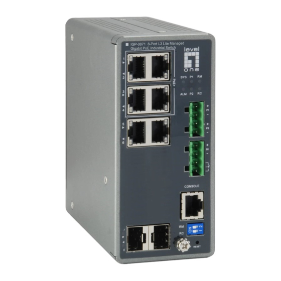
- Page 1 IGP-0871 8-Port L3 Lite Managed Gigabit PoE Industrial Switch Quick Installation and Initial Configuration...
-
Page 2: Table Of Contents
Contents Chapter 1 Introduction ............ 1 Overview ................1 Front View of the Switch ............ 1 Rear View of the Switch ............2 LED Descriptions ..............2 DIP Switch ................5 Reset Button ............... 5 Chapter 2 Installing the Switch ........6 Package Contents ............... -
Page 3: Chapter 1 Introduction
Overview This user guide describes how to install, configure, and troubleshoot the IGP-0871, 8-Port L3 Lite Managed Gigabit PoE Industrial Switch. By reading this user guide, users can perform the following tasks: To check the switch status by reading the LED behavior •... -
Page 4: Rear View Of The Switch
Rear View of the Switch Figure 2: Rear panel of the switch LED Descriptions The LEDs on the front panel provide users with switch status checking and monitoring. There are three types of LEDs as follows: Power LEDs • indicates if the switch is powered up correctly or not. System LED •... - Page 5 indicates the current status of each port. Users can check these LEDs to understand the port status. The following table details the functions and descriptions of various LED indicators. Table 1: Power LEDs Color State Description The switch is powered ON correctly. Power1 Green The switch is not receiving power from...
- Page 6 Rapid Chain has been detected in the switch. (Backup path) Amber Error: Blinking There is no correspondent Rapid Chain Switch found. Disable Users can check the port status by reading the LED behaviors per the table below. Table 5: Port Status LEDs Color State Description...
-
Page 7: Dip Switch
The port has no active network cable connected, or it is not established a link to connected device. Otherwise, the port may have been disabled through the switch user interface. DIP Switch By configure the DIP Switch, users can perform the Rapid Ring tasks. Detail setting can refer to Rapid Ring User Manual. -
Page 8: Chapter 2 Installing The Switch
Chapter 2 Installing the Switch Package Contents IGP-0871 • Console Cable • Installation Guide • Mounting kit • Mounting the Switch on a DIN Rail Step 1 Attach the DIN Rail mounting kit to rear panel of the chassis. Insert screws and tighten then with a screwdriver to secure the kit. -
Page 9: Mounting The Switch On Wall (Optional)
Figure 4: Insert switch to the DIN Rail Step 3: Make sure that the switch is attached securely to DIN Rail. Figure 5: The switch is attached to DIN Rail Mounting the Switch on Wall (Optional) Step 1 Attach the wall mounting plates to rear panel of the chassis. Insert screws and tighten then with a screwdriver to secure the plates. -
Page 10: Connecting The Dc Power Cord
Figure 6: Attaching Wall Mounting Plates to the Switch Figure 7: The Dimension of Wall Mounting Plates Step 2: Install user-supplied screws on the appropriate location on the wall. Step 3: Make sure that the switch is attached securely to wall. Connecting the DC Power Cord Step 1: Insert the negative/positive DC wires into the V-/V+ terminals,... -
Page 11: Connecting The Di/Do Relay Wires
Step 2: To keep the DC wires from pulling loose, use a small flat-blade screwdriver to tighten the wire-clamp screws on the front of the terminal block connector. Step 3: Insert the terminal block connector prongs into the terminal block receptor. Step 4: Check the SYS LED. -
Page 12: Installing Sfp Modules
STEP 1: Insert the negative (ground)/positive DI/DO Relay wires into the +/- terminals, respectively. STEP 2: To keep the DI/DO Relay wires from pulling loose, use a small flat-blade screwdriver to tighten the wire-clamp screws on the front of the terminal block connector. STEP 3: Insert the terminal block connector prongs into the terminal block receptor. - Page 13 Figure 10: Installing a SFP Module into a SFP Port Note The SFP ports should use UL Listed Optional Transceiver product, Rated 3.3Vdc, Laser Class 1.
-
Page 14: Chapter 3 Initial Configuration Of Switch
Chapter 3 Initial Configuration of Switch Initial Switch Configuration Using Web Browsers After powering up the switch for the first time, you can perform the initial switch configuration using a web browser. For managing other switch features, please refer to the Web interface user guide for details. To begin with the initial configuration stage, you need to reconfigure your PC’s IP address and subnet mask so as to make sure the PC can communicate with the switch. - Page 15 Step 2: Select Network and Sharing Center Step 3: Click on Change adapter settings on the left of PC screen Note Users can also skip step 1 to 3, by pressing WinKey+R and type ”ncpa.cpl” command to get to step 4 directly. Step 4: Right-click on your local adapter and select Properties Step 5:...
- Page 16 If your PC is configured correctly, you will see the login page of the switch as shown by Figure 9 below. Figure 11: Web Interface login page If you do not see the above login page, please perform the following steps: - Refresh the web page.
-
Page 17: Chapter 4 Troubleshooting
Chapter 4 Troubleshooting The following table provides information for users to easily troubleshoot problems by taking actions based on the suggested solutions within. Table 7: Troubleshooting Table Possible Symptoms Suggested Solutions Causes 1. Check if correct power cord is connected firmly to the switch and to the DC outlet socket.
Need help?
Do you have a question about the IGP-0871 and is the answer not in the manual?
Questions and answers