
Related Manuals for Yamaha WOLVERINE YXE70WPAJ 2017


Summary of Contents for Yamaha WOLVERINE YXE70WPAJ 2017
- Page 1 READ THIS MANUAL CAREFULLY! It contains important safety information. OWNER’S MANUAL YXE70WPAJ YXE70WPHJ LIT-11626-31-43 B3D-F8199-10...
- Page 2 EBU31031 Operating, servicing and maintaining a passenger vehicle or off-road vehicle can expose you to chemicals including engine exhaust, carbon monoxide, phthalates, and lead, which are known to the State of California to cause cancer and birth defects or other reproductive harm. To minimize exposure, avoid breathing exhaust, do not idle the engine except as necessary, service your vehicle in a well-ventilated area and wear gloves or wash your...
- Page 3 Congratulations on your purchase of the Yamaha YXE70WPAJ / YXE70WPHJ. It represents the result of many years of Yamaha experience in the production of fine sporting, touring, and pace- setting racing vehicles. With the purchase of this Yamaha, you can now appreciate the high de- gree of craftsmanship and reliability that have made Yamaha a leader in these fields.
- Page 4 EBU31080 IMPORTANT MANUAL INFORMATION EBU31070 FAILURE TO FOLLOW THE WARNINGS CONTAINED IN THIS MANUAL CAN RESULT IN SERI- OUS INJURY OR DEATH. Particularly important information is distinguished in this manual by the following notations: This is the safety alert symbol. It is used to alert you to poten- tial personal injury hazards.
- Page 5 This vehicle complies with all state off-highway noise level and spark arrester laws and regulations. EBU31111 YXE70WPAJ / YXE70WPHJ OWNER’S MANUAL ©2017 by Yamaha Motor Corporation, U.S.A. 1st edition, August 2017 All rights reserved. Any reprinting or unauthorized use without the written permission of Yamaha Motor Corporation, U.S.A.
-
Page 6: Table Of Contents
Drive select lever ........ 4-14 EBU31120 CONTENTS Fuel tank cap........4-14 Doors..........4-15 LOCATION OF THE WARNING AND Seats ..........4-15 SPECIFICATION LABELS ....... 1-1 Adjusting the driver seat position..4-16 Seat belts ........... 4-17 SAFETY INFORMATION ......2-1 Glove compartment ......4-18 Storage compartments ...... - Page 7 Accelerator pedal ......... 5-6 PERIODIC MAINTENANCE AND Seat belts ..........5-6 ADJUSTMENT .........8-1 Passenger handhold ......5-7 Owner’s manual and tool kit....8-2 Steering ..........5-7 Maintenance charts ......8-4 Fittings and fasteners ......5-7 Hood ...........8-10 Instruments, lights and switches..5-7 Panels ..........8-11 Control cables ........5-7 Engine oil and oil filter cartridge ..8-14 Tires............
- Page 8 Checking the stabilizer bushes ..8-43 NOISE REGULATION ......11-4 Rear knuckle upper and lower pivot MAINTENANCE RECORD ....11-5 lubrication (left and right)....8-44 YAMAHA MOTOR CORPORATION, Steering shaft lubrication ....8-44 U.S.A. 2015 AND LATER MODEL Wheel removal........8-45 SIDE × SIDE LIMITED Tire replacement ........
-
Page 9: Location Of The Warning And Specification Labels
EBU31130 LOCATION OF THE WARNING AND SPECIFICATION LABELS... - Page 10 Read and understand all of the labels on your vehicle. They contain important information for safe and proper operation of your vehicle. Never remove any labels from your vehicle. If a label becomes difficult to read or comes off, a replacement label is available from your Yamaha dealer.
- Page 11 To avoid Injury, keep hands and arms completely that the vehicle may tip or roll, Inside the vehicle by holding the steering wheel or handhold. brace your feet on the floor or footrests, YAMAHA 1XD-K8483-00 and keep your hands on the steering wheel or handhold.
- Page 12 Maximum Load in Cargo Bed: 300 lbs (136 kg) Maximum Vehicle Load: 721 lbs (327 kg) YAMAHA MOTOR CORPORATION U.S.A. certifies this ROV complies with the American National Standard for Recreational • Load or trailer may affect handling and stability.
- Page 13 ISO3471 • Never set or allow tire pressure to be below the minimum. YAMAHA MOTOR CORPORATION U.S.A. Tire may dislodge from rim. 6555 Katella Avenue, Cypress, California 90630-5101, U.S.A. OPERATING TIRE PRESSURE: With tires cold, set as follows.
- Page 14 MAX 7.3 INCH Any part of your body (arms, legs, or head) outside of (185MM) the vehicle can be crushed by the YAMAHA 5UG-F151J-00 cage/frame. If you think or feel that the vehicle may tip or roll, brace your feet on...
- Page 15 Feet On floor or footrests, ready to brace, and door closed. risk of overturn or other YAMAHA 1XD-F1558-00 accidents. • Secure load to prevent it from shifting. • Never load more than 490 N (50 kgf)/110 lbf tongue weight on towing bracket.
- Page 16 Re a d T i p s Gui d e fo r th e R e cre a ti o na l O f f -H i g hway Veh i cl e D r ive r Fol low A l l I nst r ucti o n a n d Wa r n i ng s YAMAHA 2MB-F1568-00 B e P r e p a r e d A d j u s t , l o ck a n d n eve r r e m o ve h a n d h o l d .
-
Page 17: Safety Information
EBU33432 Be a responsible owner As the vehicle’s owner, you are responsible for the safe and proper operation of your Yamaha Wolverine. While understanding all parts of this manual are important for vehicle ownership, be sure to read this chapter and the instructions in Chapter 7 before operating your Yamaha Wolverine. - Page 18 Before you operate your Yamaha Wolverine Prepare yourself and your passenger: • This vehicle is intended for use only by an operator 16 or older with a valid motor vehicle li- cense. DRIVER UNDER • This vehicle is designed to carry the driver and one passenger. Never carry passengers in the cargo bed.
- Page 19 Secure cargo so that it will not shift – a loose load could change handling unexpectedly or be thrown forward and strike occupants. While using your Yamaha Wolverine Keep your body completely inside the vehicle at all times. Keep both hands on the steering wheel.
- Page 20 Abrupt maneuvers or aggressive driving, even on flat, open areas, can cause loss of control, including rollovers. The Wolverine has higher ground clearance and other features to handle rugged terrain, and, as a result, can overturn in situations where some other vehicles may not. ...
- Page 21 If you think or feel that the vehicle may tip or roll, keep your body completely inside the protec- tive structure of the vehicle: • Brace yourself by pressing your feet firmly on the floorboard and keep a firm grip on the steering wheel or passenger handhold.
- Page 22 Many companies with no connection to Yamaha manufacture parts and accessories or offer oth- er modifications for Yamaha vehicles. Yamaha is not in a position to test the products that these aftermarket companies produce. Therefore, Yamaha can neither endorse nor recommend the use of accessories not sold by Yamaha or modifications not specifically recommended by Yamaha, even if sold and installed by a Yamaha dealer.
- Page 23 Aftermarket parts, accessories, and modifications While you may find aftermarket products similar in design and quality to genuine Yamaha Acces- sories, recognize that some aftermarket accessories or modifications are not suitable because of potential safety hazards to you or others. Installing aftermarket products or having other mod- ifications performed to your Wolverine that change any of the vehicle’s design or operation char-...
-
Page 24: Description
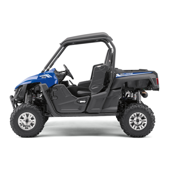
EBU31170 DESCRIPTION EBU31180 Left view 12 11 1. Front shock absorber assembly 11.Driver seat 2. Radiator cap 12.Door 3. Brake fluid reservoir 4. Air filter 5. Shoulder bolster 6. Driver seat belt 7. Cargo bed 8. Tail/brake light 9. Rear shock absorber assembly 10.Spark plug... -
Page 25: Right View
EBU31190 Right view 1. Spark arrester 2. Passenger seat belt 3. Engine oil dipstick 4. Storage compartment 5. Battery 6. Fuses 7. Headlight 8. Coolant reservoir 9. Passenger seat 10.Fuel tank cap 11.Oil filter cartridge... -
Page 26: Controls And Instruments
EBU31200 Controls and instruments 4 5,6 7 15 14 1. Light switch 9. Passenger handhold 2. On-Command drive knob 10.Glove compartment 3. Steering wheel 11.Storage compartment 4. Main switch 12.Drive select lever 5. Helmet indicator light 13.Parking brake lever 6. Seat belt indicator light 14.Accelerator pedal 7. -
Page 27: Instrument And Control Functions
EBU31217 EBU31230 INSTRUMENT AND CONTROL “ ” (on): FUNCTIONS All electrical circuits are supplied with power. The key cannot be removed. EBU31220 Main switch The helmet indicator light comes on and stays on while the key is turned to “ ”... -
Page 28: Indicator Lights And Warning Lights
EBU31268 Indicator lights and warning lights 1. Helmet indicator light “ ” 2. Seat belt indicator light “ ” 1. Differential gear lock indicator light “DIFF. LOCK” EBU31270 2. Low-range indicator light “L” Low-range indicator light “L” 3. High-range indicator light “H” This indicator light comes on when the drive 4. - Page 29 EBU31290 Neutral indicator light “N” When the On–Command drive knob is set to This indicator light comes on when the drive “DIFF LOCK”, the indicator light will flash until select lever is in the “N” position. the differential is locked. Turn the steering EBU31300 wheel back and forth or drive slowly to help Reverse indicator light “R”...
- Page 30 If the light comes on display will indicate an error code (see page during operation, stop the vehicle as soon as 4-10). Have a Yamaha dealer check the self- it is safe to do so and allow the engine to cool diagnosis system.
- Page 31 If the steering load is too heavy (e.g., exces- the indicator light remains on after the driver sive steering use at slow speed or when op- seat belt is properly latched, have a Yamaha erating in deep mud, sand, or snow), the dealer check the electrical circuit.
-
Page 32: Multi-Function Meter Unit
hour meter EBU31386 Multi-function meter unit voltage display fuel gauge error code display Speedometer The speedometer shows the vehicle’s travel- ing speed. The speedometer can be set to “mph” or “km/h”. This also changes the odometer and tripmeter units between miles and kilometers. - Page 33 Odometer and tripmeters Push the “SELECT” button to switch between the odometer “ODO” and the tripmeters “TRIP A” and “TRIP B” in the following order: ODO → TRIP A → TRIP B → ODO To reset a tripmeter, set the display to the tripmeter you want to reset, then push the “RESET”...
- Page 34 Clock, hour meter and voltage display To set the clock 1. Set the display to the clock. 2. Push both the “SELECT” button and “RESET” button for three seconds. The hour digits will start flashing. 3. Push the “RESET” button to set the hours.
- Page 35 If the voltage display indicates “LO” or “HI”, there may be trouble with the battery charging circuit or the battery may be faulty. If this occurs, have a Yamaha dealer check or repair the vehicle. Fuel gauge This display shows the battery voltage.
- Page 36 If the display indicates an error code, note the and “ ” will flash repeatedly. Have a Yamaha code number and have a Yamaha dealer dealer check the vehicle. check the vehicle.
-
Page 37: Light Switch
that the electric starter will not have EBU31391 Light switch “ ” enough power to crank the engine. If this should happen, remove the battery and re- charge it. EBU31402 On–Command drive knob “2WD/4WD/DIFF LOCK” 1. Light switch “ ” Set the switch to “... -
Page 38: Accelerator Pedal
drive with differential lock. Select the appro- EBU31412 Accelerator pedal priate drive according to the terrain and driv- ing conditions. “2WD” (two–wheel drive): Power is sup- plied to the rear wheels only. “4WD” (four–wheel drive): Power is sup- plied to the front and rear wheels. -
Page 39: Brake Pedal
To release the parking brake, pull rearward on EBU31421 Brake pedal the lever, press the release button, and then push the lever all the way forward. 1. Brake pedal Press the brake pedal to slow or stop the ve- 1. Release button hicle. -
Page 40: Drive Select Lever
EBU31441 EBU31450 Drive select lever Fuel tank cap 1. Drive select lever 1. Fuel tank cap The drive select lever is used to shift the To open transmission into the low, high, neutral, and Remove the fuel tank cap by turning it coun- reverse positions. -
Page 41: Doors
EBU31460 Doors To open a door, pull the latch outward. To close a door, push or pull the door inward un- til it is securely latched. Be sure the door is SECURELY LATCHED AFTER CLOSING IT. 1. Seat cushion To install a seat cushion, insert the projec- tions on the rear of the seat cushion under the seat frame, and then insert the projection on the front of the cushion into the grommet... -
Page 42: Adjusting The Driver Seat Position
Adjust the driver seat position as follows. 1. Remove the driver seat cushion. (See the previous section “Seats”.) 2. Remove the bolts. EBU31480 Adjusting the driver seat position The driver seat can be adjusted to one of three positions to suit the driver’s preference. 1. -
Page 43: Seat Belts
4. Install the bolts, and then tighten the bolts Always wear the seat belts properly while rid- to the specified torque. ing in the vehicle. (See page 7-5.) Tightening torque: If the vehicle is driven without the driver Driver seat bolt: seat belt fastened, a buzzer will sound. -
Page 44: Glove Compartment
EBU31502 ECB02071 NOTICE Glove compartment To protect from damage, do not put metal items, like tools, or sharply edged items di- rectly in the glove compartment. If they must be stored, wrap them in appropriate cushioning material. EBU33522 Storage compartments The storage compartments are located in the dashboard, between the driver seat and the 1. - Page 45 ECB02241 NOTICE To protect from damage, do not put metal items, like tools, or sharply edged items di- rectly in the storage compartment. If these items must be stored, wrap them in appro- priate cushioning material. 1. Storage compartment 1. Storage compartment 1.
-
Page 46: Cup Holders
about and possibly injure people in the Maximum load limit: vehicle during sudden braking or an ac- Storage compartment between the driver cident. seat and the passenger seat: 6.4 kg (13.5 lb) EBU31520 Cup holders Be sure to tightly close the cap of any plastic bottle before placing it in a cup holder. - Page 47 Do not exceed the specified maximum load limits. Heavier cargo could cause loss of control because of improper weight balance. There are six cargo hooks in the cargo bed. 1. Cargo hook Maximum load limit: 136.0 kg (300 lb) For additional loading information, see page 6-7.
-
Page 48: Front Shock Absorbers
1. Tailgate 1. Tailgate 2. Latch 2. Latch To install the tailgate EBU33614 Front shock absorbers Place the tailgate in the original position, and The shock absorber assemblies are equipped then hook the latches. with a spring preload adjusting nut, a rebound The tailgate can also be installed at the front damping force adjusting screw, a fast com- of the cargo bed. - Page 49 due to small differences in production, the ac- EWB02492 WARNING tual number of clicks or turns always repre- Suspension components become hot sents the entire adjusting range. To obtain a during operation. Never touch the com- precise adjustment, it would be advisable to pression damping force adjusting bolt check the number of clicks or turns of each and screw, the rebound damping force...
- Page 50 2. Locknut 3. Spring preload adjusting nut A special wrench can be obtained at a Yamaha dealer to make this adjustment. The spring preload setting is determined by measuring distance A, shown in the illustra- 1. Distance A tion.
- Page 51 Tightening torque: Rebound damping setting: Locknut: Minimum (soft): 30 N·m (3.0 kgf·m, 22 lb·ft) 30 click(s) in direction (b)* Standard: 13 click(s) in direction (b)* Rebound damping force Maximum (hard): Turn the rebound damping force adjusting 1 click(s) in direction (b)* screw in direction (a) to increase the rebound * With the adjusting screw fully turned in di- damping force and thereby harden the damp-...
- Page 52 Slow compression damping force To increase the slow compression damping force and thereby harden the compression damping, turn the slow compression damp- ing force adjusting screw in direction (a). To decrease the slow compression damping force and thereby soften the compression damping, turn the adjusting screw in direction (b).
-
Page 53: Rear Shock Absorbers
12 click(s) in direction (b)* out shock absorber assembly yourself. Maximum (hard): Take the shock absorber assembly to a 1 click(s) in direction (b)* Yamaha dealer for any service. * With the adjusting screw fully turned in di- rection (a) EBU33623 Rear shock absorbers... - Page 54 due to small differences in production, the ac- EWB02492 WARNING tual number of clicks or turns always repre- Suspension components become hot sents the entire adjusting range. To obtain a during operation. Never touch the com- precise adjustment, it would be advisable to pression damping force adjusting bolt check the number of clicks or turns of each and screw, the rebound damping force...
- Page 55 2. Spring preload adjusting nut 3. Special wrench A special wrench can be obtained at a Yamaha dealer to make this adjustment. The spring preload setting is determined by measuring distance A, shown in the illustra- 1. Distance A tion.
- Page 56 Tightening torque: Rebound damping setting: Locknut: Minimum (soft): 30 N·m (3.0 kgf·m, 22 lb·ft) 30 click(s) in direction (b)* Standard: 14 click(s) in direction (b)* Rebound damping force Maximum (hard): Turn the rebound damping force adjusting 1 click(s) in direction (b)* screw in direction (a) to increase the rebound * With the adjusting screw fully turned in di- damping force and thereby harden the damp-...
- Page 57 Slow compression damping force To increase the slow compression damping force and thereby harden the compression damping, turn the slow compression damp- ing force adjusting screw in direction (a). To decrease the slow compression damping force and thereby soften the compression damping, turn the adjusting screw in direction (b).
-
Page 58: Trailer Hitch Bracket And Receiver
2" (5 cm) receiver for a stan- dard trailer hitch. Trailer towing equipment highly pressurized nitrogen gas. Read and can be obtained at a Yamaha dealer. (See understand the following information be- fore handling the shock absorber assem- page 6-7 for precaution information.) -
Page 59: Auxiliary Dc Jack
EBU32951 Auxiliary DC jack 1. Trailer hitch bracket 2. Receiver 1. Auxiliary DC jack cap 2. Auxiliary DC jack This model has an auxiliary DC jack in the dashboard. A 12-V accessory with the proper plug, such as a radio or smartphone charger, can be used when the engine is running and the headlights are off. - Page 60 Do not use an automotive cigarette light- 3. Turn the accessory off. 4. Open the auxiliary DC jack cap. er or other accessories with a plug that 5. Insert the accessory power plug into the gets hot, because the jack can be dam- jack.
-
Page 61: For Your Safety - Pre-Operation Checks
Do not operate the vehicle if you find any problem. If a problem can- not be corrected by the procedures provided in this manual, have the vehicle inspected by a Yamaha dealer. Before using this vehicle, check the following points:... - Page 62 ITEM ROUTINE PAGE • Check coolant level in reservoir. Coolant 5-6, 8-24 • Fill with coolant if necessary. Final gear oil/Differen- • Check for leakage. 5-6, 5-6, 8-20, 8-22 tial gear oil Accelerator pedal • Check free play and for proper operation. Seat belts •...
-
Page 63: Front And Rear Brakes
Apply the brakes firmly for one minute. If there Check that there is no free play in the brake is any leakage, have the vehicle inspected by pedal. If there is free play, have a Yamaha a Yamaha dealer. dealer check the brake system. (See page 8-41.) - Page 64 Your Yamaha engine has been designed to lights of water heaters and clothes dry- use regular unleaded gasoline with a pump ers.
-
Page 65: Engine Oil
If you carry a portable fuel container in the do not mix any chemical additives. Do bed of your Yamaha Wolverine, be sure to se- not use oils with a diesel specification of cure it with the cap tightened before driving “CD”... -
Page 66: Coolant
It must operate smoothly and Recommended engine oil type and quantity: spring back to the idle position fully when re- See page 10-1. leased. Have a Yamaha dealer repair as nec- essary for proper operation. EBU31761 Coolant EBU31800... -
Page 67: Passenger Handhold
Always check the tightness of chassis fittings spected and any necessary replacements and fasteners before starting off. Take the ve- made as soon as possible. hicle to a Yamaha dealer or refer to the Servi- ce Manual for correct tightening torque. EBU31810 Passenger handhold... - Page 68 Tire pressure Recommended tire pressure: Use the tire pressure gauge to check and ad- Vehicle load: just tire pressures when the tires are cold. Tire 0 - maximum Front: pressures must be equal on both sides. 75.0 kPa (0.750 kgf/cm², 11 psi) WARNING! Operation of this vehicle with Rear: improper tire pressure may cause severe...
- Page 69 1. Tire pressure gauge 1. Tire wear limit Tire wear limit When the tire groove decreases to 3 mm (0.12 in) due to wear, replace the tire.
-
Page 70: Operation
If any abnormality is noticed EBU31890 during this period, consult a Yamaha dealer. Engine break-in There is never a more important period in the 0–10 hours:... -
Page 71: Starting The Engine
If the neutral indi- cator light does not come on, ask a After break-in: Yamaha dealer to inspect the electric The vehicle may now be operated normally. circuit. The engine can be started in any gear if... -
Page 72: Drive Select Lever Operation And Reverse Driving
2. Apply the brake pedal, then shift by mov- Do not turn the key to the “ ” (start) position ing the drive select lever along the shift with the engine running; otherwise, damage guide. Make sure that the drive select le- to the electric starter may result. - Page 73 5. Check behind the vehicle for people or light should be on. If the light does not obstacles, and then release the brake come on, ask a Yamaha dealer to in- pedal. spect the reverse indicator light electri- 6. Press the accelerator pedal gradually and cal circuit.
-
Page 74: On-Command Drive Knob
EBU31922 On-Command drive knob The vehicle handles differently in each of the drive modes (“2WD”, “4WD” and “DIFF LOCK”). For example, the vehicle requires more effort to turn in “DIFF LOCK” than in “2WD”. Always stop the vehicle before changing the position of the On-Command drive knob. The meter display changes according to the selected drive mode. - Page 75 When the knob is set to “DIFF LOCK” or “4WD”, the differential gear lock indicator and indica- tor light will flash until the differential gear is completely locked or unlocked. When the indicator and indicator light are flashing, turning the steering wheel back and forth will help the differential gear lock to engage or disengage.
-
Page 76: Parking
EBU31930 EWB04260 Parking WARNING When parking, stop the engine and shift the Improper loading or towing can increase drive select lever into the neutral position. Ap- the risk of loss of control, an overturn, or ply the parking brake to help prevent the ve- other accident: hicle from rolling. - Page 77 Operating when loaded with cargo or tow- MAXIMUM LOAD LIMITS ing a trailer Cargo bed: Drive more slowly than you would without a 136.0 kg (300 lb) Pulling load (gross trailer weight): load. The more weight you carry, the slower 6664 N (680 kgf, 1500 lbf) you should go.
- Page 78 Pulling something other than a trailer Yamaha recommends that loads be trans- ported in the bed or in a trailer. If you need to move an object a short distance use a winch and follow the winch manufacturer’s instruc- tions.
-
Page 79: Basic Guide For Safe Use
EBU31950 EBU33492 KNOW YOUR VEHICLE BASIC GUIDE FOR SAFE USE This off-road vehicle will handle and maneu- ver differently from cars, ATVs, go-carts, golf- EBU31961 cars and grounds-keeping vehicles. The As a Wolverine owner you are responsible for Wolverine has higher ground clearance and the safe and proper operation of this vehicle. - Page 80 The driver must be able to place both feet As the owner/operator, it is your responsibility to protect yourself and your passenger from flat on the floorboard while seated upright accidents, including rollovers. The Wolverine with his/her back against the backrest. ...
- Page 81 Passenger requirements Occupant protection system This vehicle is designed for the operator and EWB03350 WARNING one passenger. Allowing passengers to ride Do not make changes to the occupant pro- improperly can lead to serious injury or death. tection system. If you install aftermarket As the operator, you are responsible for your products or have your vehicle modified, passenger.
- Page 82 Protective structure The vehicle cage/frame provides a protective structure that helps limit intrusions by branch- es or other objects and may reduce your risk of injury in accidents. The protective structure will not protect occupants in all rollovers or accidents. Body parts outside of vehicle can be struck by passing objects or crushed during vehicle rollover.
- Page 83 Seat belts A crash can damage the restraint systems in Seat belts should be worn by the driver and your vehicle. A damaged restraint system passenger. The driver must be sure that the may not properly protect the person using it, passenger is belted before driving.
- Page 84 1. Hold the latch plate as you pull the belt 3. Push the latch plate into the buckle until it across your lap and chest. Make sure the clicks. Pull up on the latch plate to make belt is not twisted and is not caught on sure it is secure.
- Page 85 5. Position the shoulder belt over your 7. To release the buckle, firmly press the re- shoulder and across your chest. The lease button. shoulder belt should fit against your Doors chest. If it is loose, pull the belt out all the The doors are designed to reduce the likeli- way and then let it retract.
- Page 86 Passenger handhold Adjusting the handhold position The passenger handhold is provided to grip The handhold can be adjusted to one of three during operation to maintain proper position positions to suit the passenger’s preference. and balance. Holding onto the handhold helps to reduce the likelihood that the pas- senger puts a hand outside the vehicle if the vehicle begins to tip.
- Page 87 Adjust the handhold position as follows. 1. Remove the locking pins. 1. Handhold support 2. Handhold bar 3. Insert the pins into the holes and secure 1. Passenger handhold 2. Locking pin them with the wire loops. Make sure that 2.
- Page 88 1. Wire loop Floorboard Seat and shoulder bolsters The floorboard allows you to brace your feet, The seats and shoulder bolsters are designed which helps you keep your body in the vehicle to help keep you in the vehicle. Do not put in the event of an accident or rollover.
- Page 89 briefly jerk in one direction or back and forth CORRECT GRIP EXAMPLE as the tires and vehicle respond to the obsta- cle. This quick motion could injure your thumbs or wrist if your thumbs or hand(s) are inside the steering wheel. Grip the steering wheel so that your thumbs will not be hit by the spokes.
-
Page 90: Learning To Operate Your Vehicle
Eye protection (goggles, helmet face shield, EBU33543 LEARNING TO OPERATE YOUR VEHI- or protective eyewear) Over-the-ankle boots, gloves, long-sleeved shirt or jacket, and long pants Personal protective equipment An approved helmet and other personal pro- tective equipment can help in a variety of ways, including: ... - Page 91 Practice for new Yamaha Wolverine users You should become familiar with the perfor- mance characteristics of the vehicle in a lar- ge, flat area that is free of obstacles and other vehicles. Practice controlling the accelerator pedal, brakes, steering, and drive select lever.
- Page 92 Getting ready to ride If you think or feel that the vehicle may tip or Perform the Pre-Operation Checks on page roll, keep your body completely inside the 5-1. Follow the instructions starting on page protective structure of the vehicle: ...
- Page 93 Avoid higher speeds and sudden or hard ac- the vehicle down after you take your foot off celeration until you are thoroughly familiar the accelerator. Engine braking is more no- with the operation of your vehicle. Avoid sud- ticeable in four-wheel drive. Application of ve- den or hard acceleration in any turn.
- Page 94 Parking on a flat area 5. Block the front and rear wheels with When parking on a flat area, stop the engine rocks or other objects. and shift the drive select lever into the neutral Loading position. Apply the parking brake to help pre- The total weight of operator, passenger, ac- vent the vehicle from rolling.
- Page 95 Your Yamaha Wolverine has higher ground to see far enough ahead of you. Use common clearance and other features to handle rug- sense and remember that some hills are too ged terrain, and as a result, can overturn in steep for you to climb or descend. Use proper situations where some vehicles may not.
- Page 96 side of a hill, which increases your risk of roll- slow your descent. Release the brake and be- over. Practice first on gentle slopes before at- gin to coast down the hill. Use engine braking tempting steeper hills. Always check the as much as possible, gently applying the terrain carefully before attempting any hill.
- Page 97 If you are sliding or skidding, try to steer in the Pavement direction the vehicle is sliding, to regain con- This vehicle is designed for off-road use only. trol. For example, if you feel the back of the Avoid paved surfaces. Turn gradually and go vehicle start to slide to your right, steer to the slowly if you must drive on pavement.
- Page 98 Wet brakes may have reduced effectiveness. If you feel the vehicle begin to slide sideways After leaving the water, test the brakes. If nec- or fishtail (rear-wheel sliding), steer into the di- essary, apply the brakes several times to let rection of the slide if possible, to regain direc- friction dry them out.
- Page 99 muffler or exhaust pipe, or next to other hot If there is any question about your ability to parts. Check under the vehicle after operating maneuver safely over the obstacle, you in areas where combustible materials may should turn around if the ground is flat and have collected.
-
Page 100: Periodic Maintenance And Adjustment
To avoid death during service or while using the ve- possible burns, let brake components cool hicle. If you are not familiar with vehicle before touching them. service, have a Yamaha dealer perform the service. -
Page 101: Owner's Manual And Tool Kit
EBU33560 Owner’s manual and tool kit You are recommended to put this owner’s manual in the vinyl bag and always carry it in the glove compartment as shown. Put the owner’s tool kit and tire pressure gauge under the passenger seat. 1. - Page 102 If you do not have a torque wrench available during a service operation requiring one, take your vehicle to a Yamaha dealer to check the torque settings and adjust them as neces- sary.
-
Page 103: Maintenance Charts
Even if the vehicle isn’t driven for the stated mileage or engine hours, the month maintenance intervals should still be followed. Items marked with an asterisk should be performed by a Yamaha dealer as they require special tools, data and technical skills. EBU32032... - Page 104 INITIAL EVERY month Whichev- ITEM ROUTINE er comes 1200 2400 2400 4800 first (mi) (200) (750) (1500) (1500) (3000) hours • Check for leakage. • Check for looseness and tighten all screw √ √ √ Exhaust system clamps and joints if necessary. •...
- Page 105 EBU32114 General maintenance and lubrication INITIAL EVERY month Whichev- ITEM ROUTINE er comes 1200 2400 2400 4800 first (mi) (200) (750) (1500) (1500) (3000) hours • Check coolant leakage. √ √ √ √ √ • Repair if necessary. Cooling system •...
- Page 106 INITIAL EVERY month Whichev- ITEM ROUTINE er comes 1200 2400 2400 4800 first (mi) (200) (750) (1500) (1500) (3000) hours • Check operation/brake pad wear/fluid leak- age. √ √ √ √ √ Rear brake • Correct if necessary. Replace pads if worn to the limit.
- Page 107 INITIAL EVERY month Whichev- ITEM ROUTINE er comes 1200 2400 2400 4800 first (mi) (200) (750) (1500) (1500) (3000) hours • Check for cracks or other damage, and re- √ √ √ 17 * Stabilizer bushes place if necessary. Rear knuckle up- √...
- Page 108 Hydraulic brake service • Regularly check and, if necessary, correct the brake fluid level. • Every two years replace the internal components of the brake master cylinder and calipers, and change the brake fluid. • Replace the brake hoses every four years and if cracked or damaged.
-
Page 109: Hood
EBU32340 Hood To remove 1. Pull the tab on each hood lock up, and then turn the hood locks 1/4 turn clock- wise. 1. Tab 2. Hood lock 2. Remove the hood. 1. Tab 1. Hood 8-10... -
Page 110: Panels
To install EBU33602 Panels 1. Insert the projections on the hood into the slots in the front grill, and then place the Left panel hood in the original position. To remove the left panel 1. Remove the bolts. 2. Turn the hood locks 1/4 turn counter- clockwise, and then push the tab on each 1. - Page 111 1. Quick fastener screw 1. Bolt 2. Right panel 3. Pull the panel outward. 2. Open the passenger door, and then re- 4. Close the driver door. move the quick fastener screws. To install the left panel Open the driver door, place the panel in the original position, and then install the bolts and quick fastener screws.
- Page 112 Right rear panel To remove the right rear panel 1. Remove the right panel. 2. Remove the quick fastener screws, and then take the panel off. 1. Quick fastener screw 3. Remove the fuel tank cap. (See page 4-14.) 4. Pull the panel outward. 5.
-
Page 113: Engine Oil And Oil Filter Cartridge
EBU33705 Recommended engine oil: Engine oil and oil filter cartridge See page 10-1. Check engine oil level before each operation. Oil quantity: In addition, change the oil and the oil filter car- Without oil filter cartridge replacement: tridge at the intervals specified in the periodic 2.20 L (2.33 US qt, 1.94 Imp.qt) maintenance and lubrication chart. - Page 114 6. With the arrow mark pointing in the direc- tion shown, insert the dipstick completely into the oil filler hole and then remove it again to check the oil level. 1. Rubber cover 5. Remove the engine oil dipstick and wipe it with a clean rag.
- Page 115 1. Engine oil dipstick 1. Engine oil dipstick 2. Maximum level mark 2. Arrow mark 3. Minimum level mark 9. Install the rubber cover. 10. Install the passenger seat cushion. The engine oil should be between the mini- To change the engine oil (with or without mum and maximum level marks.
- Page 116 1. Rubber cover 1. Engine oil drain bolt 2. Gasket 5. Remove the engine oil dipstick. 6. Place an oil pan under the engine to col- lect the used oil. Skip steps 8–10 if the oil filter cartridge is not 7.
- Page 117 An oil filter wrench is available from a Yamaha dealer. 1. O-ring 10. Install the new oil filter cartridge with an oil filter wrench, and then tighten it to the specified torque with a torque wrench. 1. Oil filter cartridge 2.
- Page 118 1. Torque wrench 1. Engine oil dipstick 2. Arrow mark 11. Install the engine oil drain bolt and its new gasket, and then tighten the bolt to the specified torque. Be sure to wipe off spilled oil on any parts af- ter the engine and exhaust system have Tightening torque: cooled down.
-
Page 119: Final Gear Oil
15. Turn the engine off, wait at least 10 minu- Checking the final gear oil level tes, and then check the oil level and cor- 1. Park the vehicle on a level surface. rect it if necessary. 2. Remove the final gear oil filler bolt and its 16. - Page 120 4. Check the gasket for damage, and re- place it if necessary. 5. Install the oil filler bolt and its gasket, and then tighten the bolt to the specified torque. Tightening torque: Final gear oil filler bolt: 23 N·m (2.3 kgf·m, 17 lb·ft) 1.
-
Page 121: Differential Gear Oil
ECB03600 NOTICE GL-4 is a quality and additive rating; GL-5 When checking or changing the differen- rated hypoid gear oils may also be used. tial gear oil, make sure that no foreign ma- If desired, an SAE 80W-90 hypoid gear oil terial enters the differential gear case. - Page 122 Tightening torque: Differential gear oil filler bolt: 23 N·m (2.3 kgf·m, 17 lb·ft) Changing the differential gear oil 1. Park the vehicle on a level surface. 2. Place an oil pan under the differential gear case to collect the used oil. 3.
-
Page 123: Coolant
4. Install the differential gear oil drain bolt Tightening torque: and its new gasket, and then tighten the Differential gear oil filler bolt: bolt to the specified torque. 23 N·m (2.3 kgf·m, 17 lb·ft) 8. Check for oil leakage. If oil leakage is Tightening torque: Differential gear oil drain bolt: found, check for the cause. - Page 124 If genuine Yamaha coolant is not available, use an ethylene glycol antifreeze containing corrosion inhibitors for aluminum engines and mix with distilled water at a 1:1 ratio. ECB02190 NOTICE Mix antifreeze with distilled water only. However, if distilled water is not available, 1.
- Page 125 3. When the engine is cool, remove the radi- ator cap. WARNING! Never attempt to remove the radiator cap when the en- gine is hot. [EWB04250] 1. Coolant drain bolt 2. Gasket 6. Remove the coolant reservoir cap. 1. Radiator cap 4.
- Page 126 Tightening torque: Coolant drain bolt: 8 N·m (0.8 kgf·m, 5.9 lb·ft) 11. Connect the coolant reservoir hose. 12. Pour the specified amount of fresh cool- ant into the radiator, then install the radi- ator cap. 13. Pour the specified amount of fresh cool- ant into the reservoir, then install the res- 1.
-
Page 127: Water Pump Air Bleed Bolt
1. Water pump air bleed bolt 1. Cylinder head air bleed bolt 16. When coolant begins to flow out, tighten 18. When coolant begins to flow out, tighten the bleed bolt. the bleed bolt. Tightening torque: Tightening torque: Water pump air bleed bolt: Cylinder head air bleed bolt: 8 N·m (0.8 kgf·m, 5.9 lb·ft) 10 N·m (1.0 kgf·m, 7.4 lb·ft) -
Page 128: Axle Boots
22. Check the coolant level in the reservoir and replenish if necessary. 23. Install the panels and the hood. EBU32400 Axle boots Check the axle boots for holes or tears. 1. Rear axle boot If any damage is found, have them replaced by a Yamaha dealer. 8-29... -
Page 129: Spark Plug Inspection
EBU33570 Spark plug inspection Removal 1. Remove the spark plug cap. 1. Spark plug wrench Inspection The spark plug is an important engine com- ponent and is easy to inspect. The condition 1. Spark plug cap of the spark plug can indicate the condition of 2. -
Page 130: Tightening Torque
and erode. If electrode erosion becomes ex- Spark plug gap: cessive, or if carbon and other deposits are 0.8–0.9 mm (0.031–0.035 in) excessive, you should replace the spark plug with the specified plug. Installation 1. Clean the surface of the spark plug gas- Specified spark plug: ket and its mating surface, and then wipe NGK/CPR7EA-9... -
Page 131: Cleaning The Air Filter Element
1. Remove the storage compartment locat- EBU33581 Cleaning the air filter element ed between the driver seat and the pas- The air filter element should be cleaned every senger seat as shown. 20–40 hours. It should be cleaned and lubri- cated more often if the vehicle is operated in extremely dusty areas. - Page 132 1. Air filter case cover 1. Air filter element 2. Snap holder 4. While pushing the projections on the air 3. Pivot holder filter frame inward, remove the air filter el- 3. Remove the air filter element. ement holder. 8-33...
- Page 133 1. Air filter element holder 1. Air filter element holder 2. Projection 2. Sponge material 3. Air filter frame 5. Remove the sponge material from the air 6. Wash the sponge material gently but filter frame. thoroughly in parts cleaning solvent. WARNING! Using gasoline or other flammable solvents to clean the air fil- ter element can cause a fire or explo-...
- Page 134 11. Thoroughly apply Yamaha foam air filter oil or other quality liquid foam air filter oil (not spray type) to the sponge material. The sponge material should be wet but not dripping. 12. Pull the sponge material over its frame.
-
Page 135: Air Filter Check Hoses
If water drains from the V-belt case after re- moving the drain plug, have a Yamaha dealer inspect the vehicle, as the water may affect other engine parts. 8-36... -
Page 136: Cleaning The Spark Arrester
1. V-belt case drain plug 1. Tailpipe bolt 2. Remove the tailpipe by pulling it out of EBU32450 Cleaning the spark arrester the muffler, and then remove the gasket. EWB03370 3. Tap the tailpipe lightly, and then use a WARNING wire brush to remove any carbon depos- Hot exhaust system may cause burns. -
Page 137: Valve Clearance
2. Spark arrester professional knowledge. Brake service 3. Tailpipe should be performed by a Yamaha dealer. 4. Install the gasket, and then insert the tail- EWB02572 pipe into the muffler and align the bolt WARNING holes. Operating with improperly serviced or ad- 5. -
Page 138: Checking The Front And Rear Brake Pads
If a brake pad has worn to the point that the wear indi- cator grooves have almost disappeared, have a Yamaha dealer replace the brake pads as a 1. Brake pad wear indicator groove set. - Page 139 Clean the filler cap before removing. Use only DOT 4 brake fluid from a sealed container. Use only the specified brake fluid; other- wise, the rubber seals may deteriorate, causing leakage. Refill with the same type of brake fluid. Adding a brake fluid other than DOT 4 may result in a harmful chemical reac- tion.
-
Page 140: Brake Fluid Replacement
EBU32530 Checking the brake pedal brake fluid level to gradually go down. A low Have a Yamaha dealer check the brakes at brake fluid level may indicate worn brake the intervals specified in the periodic mainte- pads and/or brake system leakage; therefore, nance and lubrication chart. -
Page 141: Parking Brake
Parking brake Pull the parking brake lever rearward com- pletely. If the parking brake lever clicks eight times or more, have a Yamaha dealer adjust the parking brake because the braking force of the parking brake is weak. In addition, have... -
Page 142: Cable Inspection And Lubrication
Cables can also become frayed or kinked. Lubricate the cable ends. If the cables do not operate smoothly, ask a Yamaha dealer to re- EBU32582 place them. Checking the stabilizer bushes... -
Page 143: Rear Knuckle Upper And Lower Pivot Lubrication (Left And Right)
Front EBU32590 Rear knuckle upper and lower pivot lu- brication (left and right) Lubricate the knuckle upper and lower pivots with a grease gun. Rear Recommended lubricant: Lithium-soap-based grease EBU32600 Steering shaft lubrication Lubricate the pivot points. Recommended lubricant: Lithium-soap-based grease 8-44... -
Page 144: Wheel Removal
2. Elevate the vehicle and place a suitable recommended in this owner’s manual. The stand under the frame. tires that came with your Yamaha Wolverine 3. Remove the nuts from the wheel. were designed to match the performance ca- 4. Remove the wheel. -
Page 145: Wheel Installation
Wolverine can affect handling and stabili- EWB03400 ty. This can cause a loss of control. WARNING Do not reverse the rims on your Yamaha The tires listed below have been approved by Wolverine to widen the track width. Install- Yamaha Motor Manufacturing Corporation of ing wheels improperly increases the risk of America for this model. -
Page 146: Battery
INTERNAL: Drink large quantities of water EBU32643 Battery or milk. Follow with milk of magnesia, This model is equipped with a 12–volt VRLA beaten egg, or vegetable oil. Get prompt (valve–regulated lead–acid) battery. There is medical attention. no need to check the electrolyte or to add dis- EYES: Flush with water for 15 minutes and tilled water. - Page 147 Remove it from vehicle and confirm the rec- positive lead. [ECB01002] ommended charging rate as specified on the battery itself. Select a suitable charger and follow the manufacturer’s instructions, or have a Yamaha dealer charge it for you. 8-48...
- Page 148 Keep in mind that the battery tends to dis- ECB00942 NOTICE charge more quickly if the vehicle is Always keep the battery charged. Stor- equipped with optional electrical accesso- ing the battery in a discharged state for ries. an extended period of time will cause ECB00933 NOTICE...
-
Page 149: Jump-Starting
EBU32651 Jump-starting Jump-starting the vehicle should be avoided. The battery should be removed and charged instead. However, if the vehicle must be jump-started, proceed as follows. EWB03430 WARNING To avoid battery explosion and/or serious damage to the electrical system: 1. Positive battery lead (red) ... - Page 150 vehicle and the other end of the positive lead to the positive terminal of the charged battery. 1. Jumper cable negative lead 5. Start the engine. (See page 6-2.) 6. After the engine starts, disconnect the 1. Jumper cable positive lead negative lead of the jumper cable from 4.
-
Page 151: Fuse Replacement
Fuse box EBU32663 Fuse replacement The fuses are located under the hood. If an electrical problem is suspected, check the fuses and replace if necessary. General layout 1 2 3 4 5 6 1. Backup fuse “BACK UP” (for clock) 2. - Page 152 1. Turn off all electrical systems. (See page Specified fuses: 4-1.) Main fuse: 2. Remove the hood. (See page 8-10.) 40.0 A Fuel injection system fuse: 3. Remove the blown fuse, and then install a 10.0 A new fuse of the specified amperage. Headlight fuse: WARNING! Always use a fuse of the 15.0 A...
-
Page 153: Replacing A Headlight Bulb
Yamaha dealer check the electrical sys- tem. 5. Install the hood. EBU32671 Replacing a headlight bulb If a headlight bulb burns out, replace it as fol- lows. 1. Remove the cover at the rear of the head- light by pulling it off. - Page 154 clean off any dirt and fingerprints us- ing a cloth moistened with alcohol or thinner. [ECB00653] 1. Headlight bulb holder 5. Wait for the headlight bulb to cool before touching or removing it. Remove the 1. Do not touch the glass part of the bulb. burnt-out bulb by pulling it out.
-
Page 155: Headlight Beam Adjustment
Tail/brake light bulb replacement ECB00691 If a tail/brake light bulb burns out, replace it as NOTICE follows: It is advisable to have a Yamaha dealer 1. Remove the tail/brake light bulb holder make this adjustment. (together with the bulb) by turning it counterclockwise. -
Page 156: Troubleshooting
The troubleshooting chart describes a quick, easy procedure for making checks. If your vehicle requires any repair, take it to a Yamaha deal- The skilled technicians at a Yamaha dealer- ship have the tools, experience, and know- how to properly service your vehicle. -
Page 157: Troubleshooting Charts
Remove the spark plug and check the electrodes. The engine does not start. Have a Yamaha dealer check the vehicle. Check the compression. 4. Compression The engine does not start. There is compression. - Page 158 Restart the engine. If the engine overheats again, ask a Level is OK. Yamaha dealer to inspect and/or repair the cooling system. Tap water can be used in an emergency. Change to the recommended coolant as soon as possible.
-
Page 159: Cleaning And Storage
may have reduced stopping ability, in- EBU32720 CLEANING AND STORAGE creasing the chance of an accident. NOTICE: Excessive water pres- EBU33681 [EWB03471] Cleaning sure may cause water seepage and Frequent, thorough cleaning of your vehicle deterioration wheel bearings, will not only enhance its appearance but will brakes, transmission seals and electri- improve its general performance and extend cal devices. -
Page 160: Storage
6. Clean the seats with a vinyl upholstery the specified amount of Fuel Med Rx, cleaner to keep the covers pliable and available from your Yamaha dealer, or glossy. equivalent product. Follow the instruc- 7. Automotive-type wax may be applied to tions on the product label. - Page 161 30 °C [90 °F] or less than 0 °C [32 °F]). Use of Fuel Med Rx or another high-quality fuel stabilizer eliminates the need to drain the fuel system. Consult a Yamaha dealer if the fuel system needs to be drained.
-
Page 162: Specifications
EBU32750 SPECIFICATIONS Dimensions: Starting system: Electric starter Overall length: Lubrication system: 2970 mm (116.9 in) Wet sump Overall width: Engine oil: 1540 mm (60.6 in) Overall height: Recommended brand: 1885 mm (74.2 in) YAMALUBE Wheelbase: Type: 2065 mm (81.3 in) SAE 0W-30, 10W-30, 10W-40, 15W-40, 20W-40 or 20W- Ground clearance: 290 mm (11.4 in) - Page 163 With oil filter cartridge replacement: Spark plug (s): 2.30 L (2.43 US qt, 2.02 Imp.qt) Manufacturer/model: Final gear oil: NGK/CPR7EA-9 Type: Spark plug gap: SAE 80 API GL-4 Hypoid gear oil 0.8–0.9 mm (0.031–0.035 in) Quantity: Clutch: 0.64 L (0.68 US qt, 0.56 Imp.qt) Clutch type: Differential gear oil: Wet, centrifugal automatic...
- Page 164 Size: Front wheel: 26 x 8-12NHS Wheel type: Manufacturer/model: Cast wheel MAXXIS/MU09 Rim size: Rear tire: 12 x 6.0AT Type: Rear wheel: Tubeless Wheel type: Size: Cast wheel 26 x 10-12NHS Rim size: Manufacturer/model: 12 x 7.5AT MAXXIS/MU10 Front brake: Loading: Type: Maximum loading limit:...
- Page 165 Spring/shock absorber type: Engine trouble warning light: Coil spring/gas-oil damper Wheel travel: Parking brake indicator light: 269 mm (10.6 in) Electrical system: High-range indicator light: Ignition system: Low-range indicator light: Charging system: Differential gear lock indicator light: AC magneto Battery: EPS warning light: Model: U1-H11L...
- Page 166 Four-wheel-drive motor fuse: 10.0 A Radiator fan motor fuse: 25.0 A 10-5...
-
Page 167: Consumer Information
This number can be used for ordering a new mation in the spaces provided for assistance key. when ordering spare parts from a Yamaha dealer or for reference, in case the vehicle is stolen. KEY IDENTIFICATION NUMBER: VEHICLE IDENTIFICATION NUMBER: 1. - Page 168 The model label can be found under the driver haust emissions as required by federal law, seat. Record the information on this label in state law and Environment Canada. the space provided. This information will be needed to order spare parts from your Yamaha dealer. 11-2...
- Page 169 1. Vehicle Emission Control Information label 11-3...
-
Page 170: Noise Regulation
EBU32830 NOISE REGULATION TAMPERING WITH NOISE CONTROL SYSTEM PROHIBITED: Federal law prohibits the following acts or the causing thereof: (1) The removal or rendering in- operative by any person other than for purposes of maintenance, repair, or replacement of any device or element of design incorporated into any new vehicle for the purpose of noise control prior to its sale or delivery to the ultimate purchaser or while it is in use or (2) the use of the vehicle after such device or element of design has been removed or rendered inoperative by any person. -
Page 171: Maintenance Record
EBU32840 MAINTENANCE RECORD Copies of work orders and/or receipts for parts you purchase and install will be required to do- cument maintenance done in accordance with the warranty. The chart below is printed only as a reminder to you that the maintenance work is required. It is not acceptable proof of mainte- nance work. -
Page 172: Yamaha Motor Corporation, U.s.a. 2015 And Later Model Side × Side Limited Warranty
EBU32854 YAMAHA MOTOR CORPORATION, U.S.A. 2015 AND LATER MODEL SIDE × SIDE LIMITED WARRANTY Yamaha Motor Corporation, U.S.A. hereby warrants SPECIFIC EXCLUSIONS from this warranty shall this warranty to remain in effect, this inspection and that new Yamaha Side x Side models purchased from... - Page 173 Attention: Warranty Department 3. Each Yamaha Side x Side dealer is held responsible for his setup, service and war-ranty repair work. This will ensure that Yamaha Motor Corporation, U.S.A. has an up-to-date registration record in accordance with federal law.
-
Page 174: Yamaha Extended Service (Y.e.s.)
This excellent Y.E.S. plan coverage is only available to dealer to see how comfor ting uninterr upted factor y- Yamaha owners like you, and only while your Yamaha is still backed protection can be. within the Yamaha Limited Warranty period. So visit your authorized Yamaha dealer to get all the facts. - Page 175 Yamaha. See your dealer today! A special note: YAMAHA EXTENDED SERVICE If visiting your dealer isn’t convenient, contact Yamaha with your Vehicle Identification Number. We’ll be happy to help you get the Y.E.S. coverage you need. Yamaha Service Marketing P.O. Box 6555...
-
Page 176: Index
INDEX Differential gear oil, Periodic maintenance ....8-22 Differential gear, Pre-operation check ......5-6 Doors ................4-15 Driver seat position ............4-16 Accelerator pedal ............4-12 Drive select lever ............4-14 Accelerator pedal, Pre-operation check ......5-6 Drive select lever operation and reverse driving .... 6-3 Air filter check hoses ............8-36 Drivetrain icon .............. - Page 177 Parking brake lever ............4-13 Passenger handhold, Pre-operation check ....5-7 Identification number records ........11-1 Indicator lights and warning lights ......... 4-2 Instruments, lights and switches, Pre-operation Rear knuckle upper and lower pivot, lubrication ..8-44 check ................5-7 Reverse indicator light ...........
- Page 178 V-belt case drain plug ..........8-36 Vehicle Emission Control Information label ....11-2 Vehicle identification number ........11-1 Warranty, extended ............11-8 Warranty, limited ............11-6 Wheel installation ............8-46 Wheel removal .............8-45 12-3...
- Page 179 EBU32880 For your best ownership experience, think Genuine Yamaha! Genuine Yamaha Parts – Genuine Yamaha replacement parts are the exact same parts as the ones originally equipped on your vehicle, providing you with the performance and durability you have come to expect.
- Page 180 PRINTED IN USA 2017.08-0.3×1 CR...
Need help?
Do you have a question about the WOLVERINE YXE70WPAJ 2017 and is the answer not in the manual?
Questions and answers