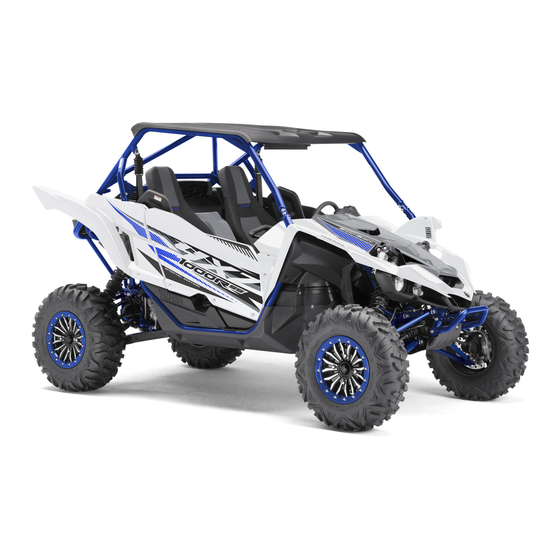
Yamaha YXZ1000R Owner's Manual
Hide thumbs Also See for YXZ1000R:
Table of Contents

Advertisement

READ THIS MANUAL CAREFULLY!
It contains important safety information.
OWNER'S MANUAL
YXZ10YEXK
YXZ10YESK
B5H-F8199-7A

Advertisement

Table of Contents
loading

Summary of Contents for Yamaha YXZ1000R

  • Page 1 READ THIS MANUAL CAREFULLY! It contains important safety information. OWNER’S MANUAL YXZ10YEXK YXZ10YESK B5H-F8199-7A...
  • Page 2 Read this manual carefully before operating this vehicle. This manual should stay with this ve- hicle if it is sold. EC Declaration of Conformity conforming to Directive 2006/42/EC We, YAMAHA MOTOR CO., LTD. 2500 Shingai, Iwata, Japan, declare in sole responsibility, that the product YXZ1000ETS (YXZ10YESK) (5Y4AN30W0J0500101–) YXZ1000ETS (YXZ10YESK) (5Y4AN38W0J0500101–) YXZ1000ET (YXZ10YEXK) (5Y4AN34W0J0500101–)
  • Page 3 Congratulations on your purchase of the Yamaha YXZ10YEXK / YXZ10YESK. It represents the result of many years of Yamaha experience in the production of fine sporting, touring, and pace- setting racing vehicles. With the purchase of this Yamaha, you can now appreciate the high de- gree of craftsmanship and reliability that have made Yamaha a leader in these fields.
  • Page 4 EBU31080 IMPORTANT MANUAL INFORMATION EBU31070 FAILURE TO FOLLOW THE WARNINGS CONTAINED IN THIS MANUAL CAN RESULT IN SERI- OUS INJURY OR DEATH. Particularly important information is distinguished in this manual by the following notations: This is the safety alert symbol. It is used to alert you to poten- tial personal injury hazards.
  • Page 5 It is illegal to operate this vehicle on public lands where vehicles its size are prohibited. EBU33130 YXZ10YEXK / YXZ10YESK OWNER’S MANUAL ©2019 by Yamaha Motor Co., Ltd. 1st edition, June 2018 All rights reserved. Any reprinting or unauthorized use without the written permission of Yamaha Motor Co., Ltd.
  • Page 6: Table Of Contents

    EBU31120 Parking brake lever ......4-23 CONTENTS YCC-S system........4-23 Drive select lever and shift paddles ... 4-24 LOCATION OF THE WARNING AND Fuel tank cap........4-25 SPECIFICATION LABELS ....... 1-1 Doors..........4-25 Seats ..........4-26 SAFETY INFORMATION ......2-1 Adjusting the driver seat position..
  • Page 7 Fuel............5-3 Selecting the drive mode....6-10 Engine oil..........5-5 Parking..........6-12 Transmission ........5-6 Loading..........6-12 Coolant ..........5-6 BASIC GUIDE FOR SAFE USE....7-1 Final gear..........5-6 KNOW YOUR VEHICLE ......7-1 Differential gear ........5-6 LEARNING TO OPERATE YOUR Accelerator pedal ......... 5-6 VEHICLE ...........7-12 Seat belts ..........
  • Page 8 Cleaning the air filter case check Rear knuckle upper and lower pivot hoses ..........8-44 lubrication (left and right) ....8-56 Cleaning the spark arrester ....8-45 Drive shaft universal joint Valve clearance ........8-47 lubrication .........8-56 Brakes ..........8-47 Steering shaft lubrication....8-56 Checking the front and rear brake Wheel removal ........8-57 pads..........
  • Page 9 SPECIFICATIONS ......... 10-1 CONSUMER INFORMATION ....11-1 Identification number records .... 11-1 Vehicle data recording ....... 11-2 INDEX............ 12-1...
  • Page 10: Location Of The Warning And Specification Labels

    EBU31130 LOCATION OF THE WARNING AND SPECIFICATION LABELS...
  • Page 11 17 18 22 21...
  • Page 12 Read and understand all of the labels on your vehicle. They contain important information for safe and proper operation of your vehicle. Never remove any labels from your vehicle. If a label becomes difficult to read or comes off, a replacement label is available from your Yamaha dealer.
  • Page 13 1 YXZ10YEXK WARNING YXZ1000ET 2018 83.5 kW YAMAHA MOTOR CO.,LTD. 691 kg 2500 SHINGAI,IWATA,JAPAN B5H-F155A-10 1 YXZ10YESK (SE model) YXZ1000ETS 2018 Any part of your 83.5 kW body (arms, legs, YAMAHA MOTOR CO.,LTD. 709 kg or head) outside of 2500 SHINGAI,IWATA,JAPAN...
  • Page 14 AVERTISSEMENT Do not rest hands or arms on door or shoulder bolster. To avoid Injury, keep hands and arms completely Inside the vehicle by holding the steering wheel or handhold. YAMAHA 1XD-K8483-00 Toute partie du corps (bras, jambes, tête) se...
  • Page 15 Poids nominal brut du véhicule : 1065 kg (2348 lbs) – Éviter les pentes et les terrains accidentés. maximum (véhicule, poids du pilote, du passager, Lire le manuel du propriétaire avant de charger la benne. des accessoires et charge). YAMAHA B5H-F4897-10 YAMAHA B5H-F1696-20...
  • Page 16 • Turn gradually and slowly. • Avoid hills and rough terrain. Gross Vehicle Weight Rating: 1065 kg (2348 lbs) • Read Owner’s Manual before loading cargo bed. maximum including vehicle, weight of operator, passenger, accessories, and cargo. YAMAHA B5H-F4897-00 YAMAHA B5H-F1696-10...
  • Page 17 Ne handholds. jamais agripper l’arceau 2HC-77762-00 Do not try to stop a de protection. vehicle tipover using your arm or Ne jamais tenter d’empê leg. cher un capotage à l’aide du bras ou de la jambe. 5B4-K7762-00 YAMAHA 1XD-K7762-10...
  • Page 18 Re a d T i p s G ui d e fo r th e R ec re at i o na l O f f -H i g h way Veh i cl e D r i ve r Fo l l ow Al l I n str u cti o n a n d War n i ng s YAMAHA 2MB-F1568-00 B e P r e p a r e d A d j u s t , l o ck a n d n eve r r e m o ve h a n d h o l d .
  • Page 19 à plat sur le plancher et qu’ils sont assis le dos contre le dossier du siège. encaisser le choc; portière fermée. • Demeurer entièrement dans l’habitacle du véhicule. YAMAHA 1XD-F1558-10 Conduire de façon responsable Prévenir la perte de contrôle ou les roulades : •...
  • Page 20: Safety Information

    Chapter 7 before operating your Yamaha YXZ1000R. Also use these two chapters and the labels on the vehicle to instruct new operators and passengers. Do not allow anyone else to operate your vehicle or ride as a passenger if you are unsure whether he or she is willing and able to follow these instructions.
  • Page 21 Before you operate your Yamaha YXZ1000R  Prepare yourself and your passenger: • This vehicle is intended for use only by an operator 16 or older with a valid motor vehicle li- cense. Check country laws for minimum age requirements.
  • Page 22 • Do not drive or ride as passenger after using drugs or alcohol. Prepare your vehicle Perform the pre-operation checks each time you use the vehicle to make sure it is in safe oper- ating condition. Failure to inspect or maintain the vehicle properly increases the possibility of an accident or equipment damage.
  • Page 23  Abrupt maneuvers or aggressive driving, even on flat, open areas, can cause loss of control, including rollovers. The YXZ1000R has higher ground clearance and other features to handle rugged terrain, and, as a result, can overturn in situations where some other vehicles may not.
  • Page 24 • Drive straight up and down inclines, not across them. If crossing a hill is unavoidable, drive slowly and turn downhill immediately if you feel the vehicle may tip. • Avoid paved surfaces. Turn gradually and go slowly if you must drive on pavement. This vehicle is designed for off-road use only.
  • Page 25  Do not operate the vehicle in fast-flowing water or water deeper than 40 cm (16 in). If you must cross shallow, slow-moving water, choose your path carefully to avoid sharp drop-offs, large rocks, or slippery surfaces. Operating this vehicle through deep or fast-flowing water can lead to loss of control or overturn.
  • Page 26 Many companies with no connection to Yamaha manufacture parts and accessories or offer oth- er modifications for Yamaha vehicles. Yamaha is not in a position to test the products that these aftermarket companies produce. Therefore, Yamaha can neither endorse nor recommend the use of accessories not sold by Yamaha or modifications not specifically recommended by Yamaha, even if sold and installed by a Yamaha dealer.
  • Page 27 Aftermarket tires and rims The tires and rims that came with your YXZ1000R were designed to match the performance ca- pabilities and to provide the best combination of handling, braking, and comfort. Other tires, rims, sizes, and combinations may not be appropriate. Refer to page 8-58 for tire specifications...
  • Page 28: Description

    EBU31170 DESCRIPTION EBU31180 Left view 1 2,3 1. Front shock absorber 11.Exhaust pipe 2. Brake fluid reservoir 12.Engine 3. YCC-S clutch fluid reservoir 13.Transmission 4. Door 5. Shoulder bolster 6. Driver seat belt 7. Coolant reservoir 8. Air filter 9. Cargo bed 10.Muffler...
  • Page 29: Right View

    EBU31190 Right view 3 4,5,6 1. Rear shock absorber 2. Engine oil tank 3. Passenger seat belt 4. Battery 5. Fuses 6. Interior light (for LE models) 7. Sun top (for LE models) 8. Rearview mirror (for SE/LE models) 9. Auxiliary light (for LE models) 10.Headlight 11.Fuel tank cap...
  • Page 30: Controls And Instruments

    EBU31200 Controls and instruments 12 10,11 1. Steering wheel 9. Passenger handhold 2. Shift paddle “ ” 10.Helmet reminder light 3. Multi-function meter unit 11.Seat belt reminder light 4. Shift paddle “ ” 12.Light switch 5. Main switch 13.On-Command drive knob 6.
  • Page 31: Instrument And Control Functions

    EBU3121A INSTRUMENT AND CONTROL The operation of the indicator and warning FUNCTIONS lights, and the multi-function meter can be EBU31221 confirmed at this time. Main switch EBU31241 Off position “ ” All electrical circuits are switched off. The key can be removed. EBU31251 Start position “...
  • Page 32: Indicator Lights And Warning Lights

    EBU31268 Indicator lights and warning lights 2 3 4 5 6 7 8 9 1. Helmet reminder light “ ” 2. Seat belt reminder light “ ” 1. Shift timing indicator light EBU35450 2. Electric Power Steering warning light “EPS” Neutral indicator light “N”...
  • Page 33 EBU34910 EBU34921 Parking brake indicator light “(P)” Drivetrain icon “ / ” This indicator light comes on when the park- The drivetrain icon indicates what type of ing brake is applied. drive mode is currently selected. When 2WD is selected, the icon will turn off. When 4WD EBU36450 is selected, “...
  • Page 34 “ ” (on), or if the so and allow the engine to idle for about 10 indicator light remains on, have a Yamaha minutes. If the warning light does not go off, dealer check the electrical circuit.
  • Page 35 (see page off. If the warning light does not come on at 4-19). Have a Yamaha dealer check the self- all, comes on in red or blue, or if the warning diagnosis system.
  • Page 36 EPS system. the indicator light does not come on and then The electrical circuit of the warning light can go off, have a Yamaha dealer check the elec- be checked by turning the key to “ ” (on). If trical circuit.
  • Page 37 ” (on). If the warning light does not the indicator light does not come on and then come on and then go off, have a Yamaha go off, have a Yamaha dealer check the elec- dealer check the electrical circuit.
  • Page 38 Stop the vehicle on level ground safely off the main trail, and have the YCC-S system serviced by a Yamaha dealer before further operation. 1. Shift arm pivot If shifting into neutral is impossible using the 2.
  • Page 39 Yamaha means. Otherwise, when the transmis- dealer check the electrical circuit.
  • Page 40: Multi-Function Meter Unit

     tachometer EBU36535 Multi-function meter unit  odometer  two tripmeters  clock  hour meter  voltage display  coolant temperature display  fuel gauge  transmission gear display  shift light control mode  error code display 1. Tachometer 2.
  • Page 41 Speedometer Tachometer 1. Speedometer 1. Tachometer 2. Tachometer red zone The speedometer shows the vehicle’s travel- The tachometer shows the engine speed in ing speed. The speedometer can be set to crankshaft revolutions per minute (r/min). “MPH” or “km/h”. This also changes the When the vehicle is first powered on, the ta- odometer and tripmeter units between miles chometer needle will sweep once across the...
  • Page 42 Red zone: 10500 r/min and above Push the “SELECT” button to switch between the odometer “ODO” and the tripmeters “TRIP A” and “TRIP B” in the following order: Odometer and tripmeters ODO → TRIP A → TRIP B → ODO To reset a tripmeter, set the display to the tripmeter you want to reset, then push the “RESET”...
  • Page 43 Clock, hour meter, voltage display and Push the “MODE” button to switch between coolant temperature display the clock “CLOCK”, the hour meter “HOUR”, the voltage display “VOLTAGE”, and the coolant temperature display in the following order: CLOCK → HOUR → VOLTAGE → coolant temperature →...
  • Page 44 If the voltage display indicates “LO” or “HI”, there may be trouble with the battery charging circuit or the battery may be faulty. If this occurs, have a Yamaha dealer check or repair the vehicle. Coolant temperature display 1. Voltage display This display shows “...
  • Page 45 low, “LO” will be displayed. When the coolant Fuel gauge temperature rises, the coolant temperature display will begin to flash. If the coolant tem- perature continues to rise, the message “HI” will flash.  The coolant temperature display can be set to “°C”...
  • Page 46 This fuel gauge is equipped with a self-diag- nosis system. If a problem is detected in an electrical circuit, the fuel gauge will flash re- peatedly. If this occurs, have a Yamaha deal- er check the electrical circuit. Transmission gear display 1.
  • Page 47  Deactivation point: this function allows you  Flash: the indicator light flashes when to select the engine speed at which the in- activated. (The indicator light will con- dicator light is deactivated. firm this setting by flashing four times per second.) To adjust the shift timing indicator light ...
  • Page 48  The tachometer needle will start over at  The tachometer needle will start over at 7000 r/min after 12000 r/min. 7000 r/min after 12000 r/min. 1. Push the “RESET” button to select the 1. Push the “RESET” button to select the desired engine speed for activating the desired engine speed for deactivating the indicator light.
  • Page 49 Error code display  YCC-S system error codes are displayed only when the engine is stopped.  If the display indicates an error code, note the code number and have a Yamaha deal- er check the vehicle. ECB00812 NOTICE If the multi-function display indicates an error code, the vehicle should be checked 1.
  • Page 50: Light Switch

    that the electric starter will not have EBU35471 Light switch “ ” enough power to crank the engine. If this should happen, remove the battery and re- charge it. EBU36942 Interior light switch “ ” (for LE mod- els) 1. Light switch “ ”...
  • Page 51: On-Command Drive Knob "2Wd/4Wd/Diff Lock

    EBU31402 On–Command drive knob “2WD/4WD/DIFF LOCK” 1. Interior light switch “ ” 1. On-Command drive knob “2WD/4WD/DIFF LOCK” Stop the vehicle and move the On–Command drive knob to change the drive mode to two– wheel drive, four–wheel drive, or four–wheel drive with differential lock.
  • Page 52: Accelerator Pedal

     “DIFF LOCK” (four–wheel drive with the dif- EBU31421 Brake pedal ferential gear locked): Power is supplied to the front and rear wheels with the differen- tial gear locked. Unlike standard four–wheel drive, all wheels turn at the same speed re- gardless of traction.
  • Page 53: Parking Brake Lever

    Parking brake lever brake engaged, a buzzer will sound. EBU36633 YCC-S system This vehicle is equipped with the Yamaha Chip Controlled-Shift system (YCC-S) with AUTO DOWNSHIFT. YCC-S allows the driver to operate the man- ual transmission without having to operate the clutch.
  • Page 54: Drive Select Lever And Shift Paddles

    engaged once the engine is running at proper EBU36652 Drive select lever and shift paddles speed. Clutch engagement is controlled by the MCU according to engine speed and oth- er driving conditions.  This is not an automatic transmission, only the clutch system is automatic.
  • Page 55: Fuel Tank Cap

    EBU31451 Fuel tank cap – 1. Shift paddle “ ” 2. Shift paddle “ ” 1. Fuel tank cap Use the shift paddles to shift through the for- Remove the fuel tank cap when refueling. To ward gears. Pull and release the shift open, turn counterclockwise.
  • Page 56: Seats

    To open a door, pull the handle. To close a door, push or pull the door inward until it is securely latched. Be sure the door is SE- CURELY LATCHED AFTER CLOSING IT. 1. Driver seat cushion 1. Door 2. Handle EBU33461 Seats To remove a seat cushion, lift the front of the...
  • Page 57: Adjusting The Driver Seat Position

    To install a seat cushion, insert the projec- EBU34993 Adjusting the driver seat position tions on the rear of the seat cushion under the The driver seat position can be adjusted to seat frame, and then insert the projection on suit the driver’s preference.
  • Page 58: Adjusting The Steering Wheel Position

    Adjust the driver seat position and make sure it is locked in place before starting off. EBU35002 Adjusting the steering wheel position The steering wheel position can be adjusted to suit the driver’s preference. WARNING! Never adjust the steering wheel position while operating the vehicle, otherwise the 1.
  • Page 59: Rearview Mirror (For Se/Le Models)

    EBU36953 EBU36184 Rearview mirror (for SE/LE models) Seat belts 1. Rearview mirror (for SE/LE models) 1. Seat belt Always wear the seat belts properly while rid- ing in the vehicle. (See page 7-5.) Adjust the rearview mirror before starting off. ...
  • Page 60: Glove Compartment

    EBU31503 ECB02071 NOTICE Glove compartment To protect from damage, do not put metal items, like tools, or sharply edged items di- rectly in the glove compartment. If they must be stored, wrap them in appropriate cushioning material. EBU38570 Storage compartments 1.
  • Page 61: Cup Holders

    ECB02241 NOTICE To protect from damage, do not put metal items, like tools, or sharply edged items di- rectly in the storage compartment. If these items must be stored, wrap them in appro- priate cushioning material. EBU31520 Cup holders Be sure to tightly close the cap of any plastic 1.
  • Page 62: Cargo Bed

     Do not place any other items than seal-  Do not exceed the specified maximum able plastic containers in the cup hold- load limits. Heavier cargo could cause ers; otherwise, they may be thrown loss of control because of improper about and possibly injure people in the weight balance.
  • Page 63: Flag Pole Bracket

    EBU35660 Flag pole bracket YXZ10YEXK: This model is equipped with a flag pole brack-  Spring preload adjusting nut  Rebound damping force adjusting screw  High speed compression damping force adjusting bolt  Low speed compression damping force adjusting screw YXZ10YESK (SE model): ...
  • Page 64 Notes on adjusting the suspension  A special wrench and special tool can be ing screw  High speed compression damping force obtained at a Yamaha dealer to make the adjusting bolt spring preload or crossover setting adjust-  Low speed compression damping force ment.
  • Page 65 and in direction (b) to decrease the spring YXZ10YESK (SE model) preload and thereby soften the suspen- sion. YXZ10YEXK 1. Locknut 2. Special wrench 3. Spring preload adjusting nut 1. Locknut 2. Special wrench 3. Spring preload adjusting nut 4-35...
  • Page 66 YXZ10YESK (LE model) Spring preload setting: Minimum (soft): Distance A = 437.6 mm (17.23 in) (YXZ10YEXK) 501.7 mm (19.75 in) [YXZ10YESK (LE model), YXZ10YESK (SE model)] Standard: Distance A = 424.9 mm (16.73 in) (YXZ10YEXK) 489.0 mm (19.25 in) [YXZ10YESK (LE model), YXZ10YESK (SE model)] Maximum (hard): 1.
  • Page 67 YXZ10YEXK 3. Tighten the locknut to the specified torque. NOTICE: Always tighten the locknut against the adjusting nut, and then tighten it to the specified torque. [ECB00082] Tightening torque: Locknut: 41 N·m (4.1 kgf·m, 30 lb·ft) Crossover setting (YXZ10YESK) 1. Distance A The crossover setting adjusts the timing when YXZ10YESK the shock absorber transitions from the soft...
  • Page 68 90˚ 1. Distance B 1. Special tool 2. Spring retainer 2. 3/8 inch (9.5 mm) drive wrench 3. Crossover locknut 3. Crossover locknut 4. Crossover adjusting nut 2. Turn the crossover adjusting nut in direc- 1. Loosen the crossover locknut as shown. tion (a) to increase the crossover setting and in direction (b) to decrease the cross- over setting.
  • Page 69 3. Tighten the locknut to the specified torque. NOTICE: Always tighten the locknut against the adjusting nut, and then tighten it to the specified torque. [ECB00082] Tightening torque: Locknut: 41 N·m (4.1 kgf·m, 30 lb·ft) 1. Distance B 2. Spring retainer 3.
  • Page 70 Rebound damping force [YXZ10YEXK / Rebound damping setting: YXZ10YESK (SE model)] Minimum (soft): Turn the rebound damping force adjusting 26 click(s) in direction (b) Standard: screw in direction (a) to increase the rebound 12 click(s) in direction (b) damping force and thereby harden the damp- Maximum (hard): ing, and in direction (b) to decrease the re- 1 click(s) in direction (b)
  • Page 71 Low speed rebound damping force To increase the rebound damping force and thereby harden the low speed rebound damping, turn the rebound damping force adjusting screw in direction (a). To decrease the rebound damping force and thereby soft- en the low speed rebound damping, turn the adjusting screw in direction (b).
  • Page 72 YXZ10YEXK / YXZ10YESK (SE model) Low speed rebound damping setting Minimum (soft): 4 turn(s) out from the fully turned in posi- tion Standard: 2 turn(s) out from the fully turned in posi- tion Maximum (hard): Adjusting screw fully turned in Compression damping force 1.
  • Page 73 YXZ10YEXK / YXZ10YESK (SE model) High speed compression damping setting Minimum (soft): 4 turn(s) out from the fully turned in posi- tion Standard: 2 turn(s) out from the fully turned in posi- tion Maximum (hard): Adjusting bolt fully turned in Low speed compression damping force 1.
  • Page 74: Rear Shock Absorbers

    Standard: out shock absorber assembly yourself. 2 turn(s) out from the fully turned in posi- Take the shock absorber assembly to a tion Yamaha dealer for any service. Maximum (hard): Adjusting screw fully turned in EBU38411 Rear shock absorbers EWB00411...
  • Page 75  Low speed rebound damping force adjust-  A special wrench and special tool can be ing screw obtained at a Yamaha dealer to make the  High speed compression damping force spring preload or crossover setting adjust- adjusting bolt ment.
  • Page 76 YXZ10YEXK ECB00091 NOTICE Never turn an adjusting mechanism be- yond the minimum and maximum settings. Spring preload 1. Loosen the locknut. 2. Turn the spring preload adjusting nut in direction (a) to increase the spring pre- load and thereby harden the suspension, and in direction (b) to decrease the spring 1.
  • Page 77 YXZ10YESK Spring preload setting: Minimum (soft): Distance A = 433.1 mm (17.05 in) (YXZ10YEXK) 610.9 mm (24.05 in) [YXZ10YESK (LE model), YXZ10YESK (SE model)] Standard: Distance A = 420.4 mm (16.55 in) (YXZ10YEXK) 598.2 mm (23.55 in) [YXZ10YESK (LE model), YXZ10YESK (SE model)] Maximum (hard): 1.
  • Page 78 YXZ10YEXK 3. Tighten the locknut to the specified torque. NOTICE: Always tighten the locknut against the adjusting nut, and then tighten it to the specified torque. [ECB00082] Tightening torque: Locknut: 41 N·m (4.1 kgf·m, 30 lb·ft) Crossover setting (YXZ10YESK) 1. Distance A The crossover setting adjusts the timing when YXZ10YESK the shock absorber transitions from the soft...
  • Page 79 90˚ 1. Distance B 1. Special tool 2. Spring retainer 2. 3/8 inch (9.5 mm) drive wrench 3. Crossover locknut 3. Crossover locknut 4. Crossover adjusting nut 2. Turn the crossover adjusting nut in direc- 1. Loosen the crossover locknut as shown. tion (a) to increase the crossover setting and in direction (b) to decrease the cross- over setting.
  • Page 80 3. Tighten the locknut to the specified torque. NOTICE: Always tighten the locknut against the adjusting nut, and then tighten it to the specified torque. [ECB00082] Tightening torque: Locknut: 41 N·m (4.1 kgf·m, 30 lb·ft) 1. Distance B 2. Spring retainer 3.
  • Page 81 Rebound damping force [YXZ10YEXK / Rebound damping setting: YXZ10YESK (SE model)] Minimum (soft): Turn the rebound damping force adjusting 26 click(s) in direction (b) Standard: screw in direction (a) to increase the rebound 12 click(s) in direction (b) damping force and thereby harden the damp- Maximum (hard): ing, and in direction (b) to decrease the re- 1 click(s) in direction (b)
  • Page 82 Low speed rebound damping force To increase the rebound damping force and thereby harden the low speed rebound damping, turn the rebound damping force adjusting screw in direction (a). To decrease the rebound damping force and thereby soft- en the low speed rebound damping, turn the adjusting screw in direction (b).
  • Page 83 YXZ10YEXK / YXZ10YESK (SE model) Low speed rebound damping setting Minimum (soft): 4 turn(s) out from the fully turned in posi- tion Standard: 2 turn(s) out from the fully turned in posi- tion Maximum (hard): Adjusting screw fully turned in Compression damping force 1.
  • Page 84 YXZ10YEXK / YXZ10YESK (SE model) High speed compression damping setting Minimum (soft): 4 turn(s) out from the fully turned in posi- tion Standard: 2 turn(s) out from the fully turned in posi- tion Maximum (hard): Adjusting bolt fully turned in Low speed compression damping force 1.
  • Page 85: Auxiliary Dc Jack

    Standard: out shock absorber assembly yourself. 2 turn(s) out from the fully turned in posi- Take the shock absorber assembly to a tion Yamaha dealer for any service. Maximum (hard): Adjusting screw fully turned in EBU35054 Auxiliary DC jack EWB03500...
  • Page 86 This model has an auxiliary DC jack located at ECB02250 NOTICE the left side of the glove compartment. A 12-  Do not use accessories requiring more V accessory with the proper plug, such as a than the stated maximum capacity. Do- radio or smartphone charger, can be used ing so may overload the circuit and cau- when the engine is running and the headlights...
  • Page 87: For Your Safety - Pre-Operation Checks

    Failure to inspect or maintain the vehicle properly increases the possibility of an accident or equipment damage. Do not operate the vehicle if you find any problem. If a problem can- not be corrected by the procedures provided in this manual, have the vehicle inspected by a Yamaha dealer. Pre-operation checklist ITEM...
  • Page 88 ITEM ROUTINE PAGE 5-6, 5-6, 5-6, 8-28, • Check front differential, transmission case, and rear final Drivetrain gear for leakage. 8-31, 8-33 • Check coolant level in reservoir. Coolant 5-6, 8-36 • Fill with coolant if necessary. Accelerator pedal • Check free play and for proper operation. Seat belts •...
  • Page 89: Front And Rear Brakes

    Apply the brakes firmly for one minute. If there  Check that there is no free play in the brake is any leakage, have the vehicle inspected by pedal. If there is free play, have a Yamaha a Yamaha dealer. dealer check the brake system. (See page 8-51.)
  • Page 90 EWB02522 EWB02532 WARNING WARNING Gasoline and gasoline vapors are ex- Gasoline is poisonous and can cause inju- tremely flammable. To avoid fires and ex- ry or death. Handle gasoline with care. plosions and to reduce the risk of injury Never siphon gasoline by mouth. If you when refueling, follow these instructions.
  • Page 91: Engine Oil

    If you carry a portable fuel container in the taining methanol is not recommended be- bed of your Yamaha YXZ1000R, be sure to cause it can cause damage to the fuel system secure it with the cap tightened before driving or vehicle performance problems.
  • Page 92: Transmission

    ECB03020 EBU36020 NOTICE Final gear  Do not use oils with a diesel specifica- Make sure there is no oil leaking from the final gear case. tion of “CD” or oils of a higher quality than specified. In addition, do not use EBU36030 oils labeled “ENERGY CONSERVING II”...
  • Page 93: Seat Belts

    Steering pushed firmly. Wash off any dirt or mud that Park on level ground. Turn the steering wheel could affect operation. Have a Yamaha dealer right and left. Check for excessive free play, repair as necessary for proper operation. abnormal noises, or a rough feeling. Have a...
  • Page 94: Ycc-S Clutch

    Check tires for wear and damage. Fittings and fasteners Always check the tightness of chassis and wheel fittings and fasteners before starting off. Take the vehicle to a Yamaha dealer or re- fer to the Service Manual for correct tighten- ing torque.
  • Page 95 Tire pressure improper tire pressure may cause severe injury or death from loss of control or roll- over. Tire pressure below the minimum specified could also cause the tire to dis- lodge from the rim under severe driving conditions. [EWB04120] 1.
  • Page 96 Tire inspection OPERATING TIRE PRESSURE (cold): VEHICLE LOAD of 0.0–195.0 kg (0–430 lb) FRONT: (Recommended) 114.0 kPa (1.140 kgf/cm², 16.5 psi) REAR: (Recommended) 128.0 kPa (1.280 kgf/cm², 18.5 psi) Front: (Minimum) 110.0 kPa (1.100 kgf/cm², 16.0 psi) Rear: (Minimum) 124.0 kPa (1.240 kgf/cm², 18.0 psi) VEHICLE LOAD of 195.0–336.0 kg (430–...
  • Page 97: Operation

    If any abnormality is noticed EBU35720 during this period, consult a Yamaha dealer. Engine break-in There is never a more important period in the 0–10 hours: life of your vehicle than the period between 0 Avoid prolonged operation above 5300 r/min.
  • Page 98: Starting The Engine

     When the transmission is in the neutral 10–20 hours: Avoid prolonged operation above 6300 r/min. position, the transmission gear display shows “N” and the neutral indicator After break-in: light should come on. The vehicle may now be operated normally. ...
  • Page 99: Shifting And Reverse Driving

    For maximum engine life, never accelerate hard when the engine is cold! EBU36723 Shifting and reverse driving This vehicle is equipped with a 5-speed for- ward and 1-speed reverse manual transmis- sion with YCC-S (see page 4-23). The transmission allows you to control the 1.
  • Page 100 ECB03370 NOTICE  To use the drive select lever, you must be Even with the transmission in the neutral pressing the brake pedal and be stopped position, do not coast for long periods of (be traveling less than 5 km/h [3 mph]), and time with the engine off.
  • Page 101 5. When vehicle speed has sufficiently in- cause loss of control, an accident and inju- creased, use the shift paddle “ ” to shift ry. It could also cause engine or drivetrain into second gear (“2”). damage. 6. Follow the same procedure when shifting to the next higher gear.
  • Page 102 To drive in reverse EWB03300 WARNING Before you shift into reverse, make sure there are no obstacles or people behind you. When it is safe to proceed, go slowly. Hitting an obstacle or person could result in serious injury or death. 1.
  • Page 103: Dynamic Clutch Engagement

     Dynamic clutch engagement works in 1st 5. Check behind you, then release the brake pedal and press the accelerator pedal gear only.  Time to engagement will vary depending on gradually. 6. Continue to watch to the rear while driv- conditions.
  • Page 104  the engine is not warmed up or is overheat- ing.  the driver seat belt is not latched.  the differential gear is locked (“DIFF LOCK” is selected) or the differential gear lock indi- cator is flashing.  the parking brake is applied. ...
  • Page 105  If the indicator light is flashing, release the accelerator pedal and let the engine return to idle speed. When the indicator light goes off, you may start off normally or retry acti- vating the launch system. 5. When ready, release both shift paddles at the same time and further press the ac- celerator pedal to launch the vehicle.
  • Page 106: Selecting The Drive Mode

    EBU35061 Selecting the drive mode The vehicle handles differently in each of the drive modes: “2WD”, “4WD” and “DIFF LOCK”. For example, the vehicle requires more effort to turn in “DIFF LOCK” than in “2WD”. Always stop the vehicle before changing the position of the On-Command drive knob. The drive mode icon changes according to the selected drive mode.
  • Page 107  When the knob is set to “DIFF LOCK” or “4WD”, the drive mode icon and the indicator light will flash until the differential gear is completely locked or unlocked.  Turning the steering wheel back and forth will help the differential gear lock to engage or dis- engage.
  • Page 108: Parking

    Cargo bed EBU35441 Parking Use the hooks equipped on the cargo bed When parking, shift into first or reverse gear, (page 4-32) to tie down loads. Make sure the stop the engine, and then apply the parking load is securely fastened down, centered in brake.
  • Page 109  Do not exceed the maximum loading limit for the cargo bed: 136.0 kg (300 lb).  Do not exceed the maximum loading limit for the vehicle: 336.0 kg (741 lb). 6-13...
  • Page 110: Basic Guide For Safe Use

    Do not allow anyone else to operate do not use care in maneuvering the the vehicle or ride as a passenger if you are YXZ1000R, you can cause it to roll over even unsure that he/she is willing and able to follow on flat, open areas.
  • Page 111 As the owner/operator, it is your responsibility to protect yourself and your passenger from accidents, including rollovers. The YXZ1000R DRIVER has many features, including a protective structure and seat belts, to help protect occu- UNDER pants, but the best way to avoid injuries is to avoid accidents.
  • Page 112 YXZ1000R. er setting rules and putting limits on how, The seat belt is not designed to restrain au- when, and where the YXZ1000R can be used. tomotive child safety seats. Passenger requirements Occupant protection system...
  • Page 113 2. Shoulder bolster 2. Shoulder bolster 3. Door 3. Door The YXZ1000R comes with a variety of fea- tures to help reduce the risk of driver and pas- senger injury. These features work together, and when properly used, these features will help protect the occupants in the event of an accident.
  • Page 114 Protective structure Seat belts The vehicle cage/frame provides a protective Seat belts should be worn by the driver and structure that helps limit intrusions by branch- passenger. The driver must be sure that the es or other objects and may reduce your risk passenger is belted before driving.
  • Page 115 A crash can damage the restraint systems in 1. Hold the latch plate as you pull the belt your vehicle. A damaged restraint system across your lap and chest. Make sure the may not properly protect the person using it, belt is not twisted and is not caught on resulting in serious injury or death in a crash.
  • Page 116 3. Push the latch plate into the buckle until it 5. Position the shoulder belt over your clicks. Pull up on the latch plate to make shoulder and across your chest. The sure it is secure. shoulder belt should fit against your chest.
  • Page 117 7. To release the buckle, firmly press the re- lease button. Doors The doors are designed to reduce the likeli- hood that you will stick your leg out to stop the vehicle from tipping over or for any other reason in a rollover. The doors may also re- duce intrusion of objects into the occupant area.
  • Page 118 Adjust the handhold position as follows. 1. Remove the locking pins. Adjusting the handhold position The handhold can be adjusted to one of three 1. Passenger handhold positions to suit the passenger’s preference. 2. Locking pin 2. Slide the handhold to the desired position and align the holes in the handhold bar with the holes in the handhold supports.
  • Page 119 1. Handhold support 1. Wire loop 2. Handhold bar Seat and shoulder bolsters 3. Insert the pins into the holes and secure The seats and shoulder bolsters are designed them with the wire loops. Make sure that to help keep you in the vehicle. Do not put the handhold is properly secured before your hand or arm on or outside of the shoul- starting off.
  • Page 120 Keep your palms on the out- side of the steering wheel. Similar to other off- road vehicles, if the YXZ1000R hits a deep rut or large obstacle, the steering wheel could 7-11...
  • Page 121: Learning To Operate Your Vehicle

    EBU36753 LEARNING TO OPERATE YOUR VEHI- CORRECT GRIP EXAMPLE Personal protective equipment INCORRECT GRIP EXAMPLE 1. Approved motorcycle helmet 2. Eye protection 3. Long-sleeved shirt or jacket 4. Gloves 5. Long pants 6. Over-the-ankle boots The driver and passenger should wear the fol- lowing to reduce risk of injury in an accident: ...
  • Page 122  Eye protection (goggles, helmet face shield, Practice for new Yamaha YXZ1000R users or protective eyewear) Become familiar with the performance char-  Over-the-ankle boots, gloves, long-sleeved acteristics of the vehicle in a large, flat area shirt or jacket, and long pants that is free of obstacles and other vehicles.
  • Page 123 Getting ready to ride Perform the pre-operation checks on page 5-1. Follow the instructions on page 6-2 when starting the engine. Turning Use care in turns — turning the steering wheel too far or too fast can result in loss of control or a rollover.
  • Page 124 If you think or feel that the vehicle may tip or Braking roll, keep your body completely inside the When slowing down or stopping, take your protective structure of the vehicle: foot off the accelerator pedal and press the  Brace yourself by pressing your feet firmly brake pedal smoothly.
  • Page 125 Leaving the vehicle Parking on a slope Do not get out of the vehicle while the engine The parking brake is located on the rear drive is running. Take the key with when you leave shaft. When the drivetrain is in “2WD” mode, the vehicle.
  • Page 126 Be aware that vehicle load includes the total the vehicle. combined weight of the operator, passenger, Your Yamaha YXZ1000R has higher ground any installed accessories, and any luggage or clearance and other features to handle rug- cargo brought on board or stored in the cargo ged terrain, and as a result, can overturn in bed.
  • Page 127 even on flat, open areas. These rollovers can sense and remember that some hills are too result in crushed limbs and other serious inju- steep for you to climb or descend. Use proper ries or death to drivers or passengers. driving techniques to avoid rearward, for- ward, or sideways rollovers on hills and slopes.
  • Page 128 over. Practice first on gentle slopes before at- then begin to coast down the hill. Use engine tempting steeper hills. Always check the braking as much as possible, gently applying terrain carefully before attempting any hill. the brakes when necessary. To climb a hill, you need traction, momentum, Downhill and steady throttle.
  • Page 129 If you are sliding or skidding, try to steer in the Pavement direction the vehicle is sliding, to regain con- This vehicle is designed for off-road use only. trol. For example, if you feel the back of the Avoid paved surfaces. Turn gradually and go vehicle start to slide to your right, steer to the slowly if you must drive on pavement.
  • Page 130 Wet brakes may have reduced effectiveness. If you feel the vehicle begin to slide sideways After leaving the water, test the brakes. If nec- or fishtail (rear-wheel sliding), steer into the di- essary, apply the brakes several times to let rection of the slide if possible, to regain direc- friction dry them out.
  • Page 131 muffler or exhaust pipe, or next to other hot If there is any question about your ability to parts. Check under the vehicle after operating maneuver safely over the obstacle, you in areas where combustible materials may should turn around if the ground is flat and have collected.
  • Page 132: Periodic Maintenance And Adjustment

    To avoid death during service or while using the ve- possible burns, let brake components cool hicle. If you are not familiar with vehicle before touching them. service, have a Yamaha dealer perform the service.
  • Page 133: Owner's Manual And Tool Kit

    EBU33561 Owner’s Manual and tool kit You are recommended to put this manual in the vinyl bag and always carry it in the glove compartment as shown. Put the tool kit and tire pressure gauge under the passenger seat. 1. Tool kit 2.
  • Page 134 Yamaha dealer to check the torque settings and adjust them as necessary.
  • Page 135: Maintenance Charts

    However, keep in mind that if the vehicle isn’t used for a long period of time, the month maintenance intervals should still be followed.  Items marked with an asterisk should be performed by a Yamaha dealer as they require special tools, data and technical skills.
  • Page 136 INITIAL EVERY month Whichev- ITEM ROUTINE er comes 1300 2500 2500 5000 first (mi) (150) (800) (1600) (1600) (3200) hours • Check breather hose for cracks or damage. √ √ √ Breather system • Replace if necessary. √ √ √ √...
  • Page 137 EBU35802 General maintenance and lubrication chart INITIAL EVERY month Whichev- ITEM ROUTINE er comes 1300 2500 2500 5000 first (mi) (150) (800) (1600) (1600) (3200) hours • Check coolant leakage. √ √ √ √ √ • Repair if necessary. Cooling system •...
  • Page 138 INITIAL EVERY month Whichev- ITEM ROUTINE er comes 1300 2500 2500 5000 first (mi) (150) (800) (1600) (1600) (3200) hours √ √ √ √ √ • Check oil level. Differential gear √ √ • Change. • Check operation and for fluid leakage. √...
  • Page 139 INITIAL EVERY month Whichev- ITEM ROUTINE er comes 1300 2500 2500 5000 first (mi) (150) (800) (1600) (1600) (3200) hours • Check balance, runout, and for damage. • Balance wheel if necessary. √ √ √ √ • Replace wheel if damaged or if runout is 14 * Wheels over specified limits.
  • Page 140 INITIAL EVERY month Whichev- ITEM ROUTINE er comes 1300 2500 2500 5000 first (mi) (150) (800) (1600) (1600) (3200) hours Drive shaft uni- √ √ √ 21 * • Lubricate with lithium-soap-based grease. versal joint • Check for cracks or other damage, and re- 22 * Drive shaft seal Every 1000 km (600 mi)
  • Page 141  The service items contained herein should not be considered exhaustive, therefore: • have your YXZ1000R checked and serviced by your Yamaha dealer at regular intervals. • replace any damaged or visibly worn part immediately. 8-10...
  • Page 142: Hood

    EBU35080 Hood To remove Remove the bolts, and then pull the hood off as shown. EBU36932 Panels The panels shown need to be removed to perform some of the maintenance jobs de- scribed in this chapter. Refer to this section each time a panel needs to be removed and 1.
  • Page 143 Panel A To remove the panel 1. Unhook the projections as shown. 1. Panel A 2. Panel B 1. Panel A 2. Projection 2. Disconnect the interior light couplers (for LE models), and then remove the panel. 1. Panel C 2.
  • Page 144 For interior-light-equipped models 1. Interior light coupler Panel B To install the panel To remove the panel 1. Connect the interior light couplers. (For 1. Remove the hood. (See page 8-11.) LE models) 2. Remove panel A. 2. Place the panel in the original position. 3.
  • Page 145 1. Top cover 1. Passenger seat 2. Bolt 2. Bolt 3. Quick fastener screw 3. Seat belt 4. Remove the passenger seat cushion. 6. Remove the quick fastener screws and (See page 4-26.) the bolts, and then pull the panel off as 5.
  • Page 146 1. Panel B 1. Panel B 2. Quick fastener screw 2. Install the passenger seat by installing the 3. Bolt bolts, and then tighten them to the spec- To install the panel ified torque. 1. Place the panel in the original position, and then install the bolts and the quick Tightening torque: Passenger seat bolt:...
  • Page 147  Place the passenger seat belt in the original position. 3. Install the passenger seat cushion. 4. Install the top cover by installing the bolts and quick fastener screw. 5. Install panel A and the hood. Panels C and D To remove a panel 1.
  • Page 148 2. Remove the panel as shown. To install a panel 1. Place the panel in the original position. 1. Panel C 1. Panel C 1. Panel D 1. Panel D 8-17...
  • Page 149: Engine Oil And Oil Filter

    2. Turn the panel lock 1/4 turn counter- ECB03020 NOTICE clockwise, and then push the tab on the  Do not use oils with a diesel specifica- panel lock down so that it is pointing rear- tion of “CD” or oils of a higher quality ward.
  • Page 150 4. Remove the engine oil tank filler cap and wipe the dipstick with a clean rag. Add oil a little at a time so as not to overfill be- yond the maximum level mark. 7. Check the O-ring for damage, and re- place it if necessary.
  • Page 151 1. Engine oil tank cover 1. Engine oil tank filler cap 2. Bolt 4. Start the engine, warm it up for several minutes, and then turn it off. 5. Remove the engine oil tank filler cap and the cylinder head cap. 1.
  • Page 152 7. Remove the oil tank drain bolt and used gasket. 1. Engine oil drain bolt 2. Gasket 3. “ ” mark 1. Engine oil tank drain bolt 2. Gasket 8. Place an oil pan under the engine to col- A “ ”...
  • Page 153 Tightening torques: Engine oil drain bolt: 10 N·m (1.0 kgf·m, 7.4 lb·ft) Engine oil tank drain bolt: 16 N·m (1.6 kgf·m, 12 lb·ft) 11. Add 2.00 L (2.11 US qt, 1.76 Imp.qt) of the recommended engine oil to the oil tank.
  • Page 154 Be sure to wipe off spilled oil on any parts af- ter the engine and exhaust system have cooled down. 16. Install and tighten the engine oil tank filler cap. 17. Start the engine and let it idle for several minutes.
  • Page 155 1. Rear bottom panel 1. Center bottom panel 2. Bolt 2. Bolt 4. Remove the bolts, and then slide the cen- 5. Follow steps 2–9 of the “To change the ter bottom panel rearward to remove it. engine oil” section for the oil draining pro- cedure.
  • Page 156 An oil filter wrench is available from a Yamaha dealer. 1. O-ring 8. Install the new oil filter cartridge, and then tighten to the specified torque. Tightening torque: 1. Oil filter cartridge 2. Oil filter wrench Oil filter cartridge: 17 N·m (1.7 kgf·m, 13 lb·ft) 7.
  • Page 157 1. Torque wrench 1. Center bottom panel 9. Follow steps 10–20 of the “To change the engine oil” section for the oil filling proce- dure. 10. Slide the front portion of the center bot- tom panel into place as shown, and then hook the left and right sides of the center bottom panel into place.
  • Page 158 1. Bolt A 1. Bolt A 2. Bolt B 2. Bolt B 3. Bolt C 3. Bolt C Tightening torques: Bolt A: 7 N·m (0.7 kgf·m, 5.2 lb·ft) Bolt B: 7 N·m (0.7 kgf·m, 5.2 lb·ft) Bolt C: 7 N·m (0.7 kgf·m, 5.2 lb·ft) 12.
  • Page 159: Transmission Oil

    1. Rear bottom panel 1. Bolt B 2. Bolt A Tightening torque: 3. Bolt B Bolt B: Tightening torques: 7 N·m (0.7 kgf·m, 5.2 lb·ft) Bolt A: 7 N·m (0.7 kgf·m, 5.2 lb·ft) EBU35107 Bolt B: Transmission oil 7 N·m (0.7 kgf·m, 5.2 lb·ft) Check the oil level and change the transmis- sion oil at the intervals specified in the general 13.
  • Page 160 ECB02910 NOTICE When checking or changing the transmis- sion oil, make sure that no foreign material enters the transmission. If necessary, clean the filler cap and surrounding area. Recommended oil: YAMALUBE SAE 5W-30, 10W-30, 10W-40, 15W-40, 1. Transmission oil filler cap 20W-40 or 20W-50 2.
  • Page 161 Add a sufficient amount to raise to the maxi- mum level mark, but do not overfill. 5. Check the O-ring for damage, and re- place it if necessary. 6. Install the transmission oil filler cap. 7. Install the panel. To change the transmission oil 1.
  • Page 162: Final Gear Oil

    ECB03590 Tightening torque: NOTICE Transmission oil drain bolt: When checking or changing the final gear 20 N·m (2.0 kgf·m, 15 lb·ft) oil, make sure that no foreign material en- ters the final gear case. If necessary, clean 6. Check the O-ring for damage, and re- the final gear oil filler bolt and surrounding place it if necessary.
  • Page 163 2. Remove the final gear oil filler bolt and its 5. Install the oil filler bolt and its gasket, and gasket, and then check the oil level in the then tighten the bolt to the specified final gear case. The oil level should be at torque.
  • Page 164: Differential Gear Oil

    7. Install the oil filler bolt and its gasket, and then tighten the bolt to the specified torque. Tightening torque: Final gear oil filler bolt: 23 N·m (2.3 kgf·m, 17 lb·ft) 8. Check for oil leakage. If oil leakage is found, check for the cause.
  • Page 165 Recommended oil: SAE 80 API GL-4 Hypoid gear oil Oil quantity: 0.18 L (0.19 US qt, 0.16 Imp.qt) If the recommended gear oil is not available, SAE 80W-90 API GL-4 or GL-5 hypoid gear oil may be used instead. 1. Differential gear oil filler bolt Checking the differential gear oil level 2.
  • Page 166 4. Install the differential gear oil drain bolt Tightening torque: and its new gasket, and then tighten the Differential gear oil filler bolt: bolt to the specified torque. 23 N·m (2.3 kgf·m, 17 lb·ft) Tightening torque: Changing the differential gear oil Differential gear oil drain bolt: 1.
  • Page 167: Coolant

    3.78 L (4.00 US qt, 3.33 Imp.qt) 3. Look at the coolant level in the coolant reservoir. If genuine Yamaha coolant is not available, use an ethylene glycol antifreeze containing corrosion inhibitors for aluminum engines and mix with distilled water at a 1:1 ratio.
  • Page 168 If water has been added to the coolant, have a Yamaha dealer check the antifreeze content of the coolant as soon as possible, otherwise the ef- fectiveness of the coolant will be re- duced.
  • Page 169: Axle Boots

    To change the coolant The coolant must be changed at the intervals specified in the periodic maintenance chart. Have a Yamaha dealer change the coolant. WARNING! Never attempt to remove the radiator cap when the engine is hot. [EWB04250] EBU32400 Axle boots Check the axle boots for holes or tears.
  • Page 170 Do not attempt to diagnose such problems yourself. Instead, have a Yamaha dealer check the vehicle. 1. Spark plug gap If a spark plug shows signs of electrode ero- Spark plug gap: sion and excessive carbon or other deposits, 0.7–0.8 mm (0.028–0.031 in)
  • Page 171: Air Filter Maintenance

    300–600 km (200–400 mi). The secondary air filter is more difficult to ac- cess, cannot be cleaned, and should be re- placed by a Yamaha dealer every 2000–5000 km (1200–3000 mi). 8-40...
  • Page 172 Additionally, the fuel injection system would be affected, resulting in poor engine Service the air filters more frequently when performance and possible overheating. operating in wet or dusty environments. Clean the primary air filter as follows. Whenever air filter maintenance is performed: 1.
  • Page 173 1. Foam air filter 1. Air filter case cover lock 2. Air filter case cover 3. Remove the foam air filter element from 3. Match mark the air filter frame. 2. Remove the foam air filter. 8-42...
  • Page 174 1. Foam air filter element 6. Wash the foam material in warm soapy 2. Air filter frame water to remove remaining solvent, then 4. Wash the foam material gently but thor- rinse thoroughly with plain warm water. oughly parts cleaning solvent.
  • Page 175: Cleaning The Air Filter Case Check Hoses

    9. Thoroughly apply Yamalube foam air filter oil (or other quality liquid foam air filter— Make sure that the match mark on the cover do not use a spray-type product) to the lock is aligned with the close match mark on foam material.
  • Page 176: Cleaning The Spark Arrester

    EBU35141 Cleaning the spark arrester EWB03370 WARNING Hot exhaust system may cause burns. To avoid burns or fires, make sure that the en- gine is stopped and the exhaust system is cool before cleaning the spark arrester. Do not start the engine while cleaning the ex- haust system.
  • Page 177 2. Remove the tailpipe bolts. 1. Gasket 2. Spark arrester 1. Tailpipe bolt 3. Tailpipe 3. Remove the tailpipe by pulling it out of 5. Install the gasket, and then insert the tail- the muffler, and then remove the gasket. pipe into the muffler and align the bolt 4.
  • Page 178: Valve Clearance

    To prevent this, the valve clear- 1.0 mm (0.04 in), have a Yamaha dealer re- ance must be adjusted regularly. This adjust- place the brake pads as a set.
  • Page 179: Checking The Parking Brake Pads

    If a brake pad has worn to the level marks. Replenish the brake and YCC-S point that the wear indicator groove has al- clutch fluids if necessary. most disappeared, have a Yamaha dealer re- place the brake pads as a set. 8-48...
  • Page 180 EWB04160 WARNING Improper maintenance can result in loss of braking ability or YCC-S clutch operation. Observe these precautions:  Insufficient brake or YCC-S clutch fluid may allow air to enter the brake or YCC-S clutch system, reducing braking or YCC-S clutch performance. ...
  • Page 181: Brake And Ycc-S Clutch Fluid Replacement

     Be careful that water or dust does not suddenly, have a Yamaha dealer check and enter the brake or YCC-S clutch fluid repair the vehicle before any further opera- reservoir when refilling. Water will signif- tion. icantly lower the boiling point of the fluid EBU36550 and may result in vapor lock.
  • Page 182: Checking The Brake Pedal

    Yamaha dealer check the YCC-S clutch. EBU32530 Checking the brake pedal Have a Yamaha dealer check the brakes at the intervals specified in the periodic mainte- nance and lubrication chart. There should be no free play in the brake pedal. The brakes should operate smoothly and there should be 1.
  • Page 183: Parking Brake Lever Free Play Adjustment

    1. Accelerator pedal 1. Parking brake lever free play 2. Accelerator pedal free play 3. Remove panel B. (See page 8-11.) 4. Release the parking brake lever. EBU35194 Parking brake lever free play adjust- 5. Slide the rubber cover back on the park- ment ing brake cable.
  • Page 184: Brake Light Switch

    The brake light, which is activated by the brake pedal, should come on just before braking takes effect. Since the brake light switch is a component of the YCC-S system, it must be adjusted by a Yamaha dealer, who has the necessary professional knowledge and experience. EBU35930 1.
  • Page 185: Pedal Lubrication

    Lubricate the cable ends. If the cables do not Recommended lubricant: operate smoothly, ask a Yamaha dealer to re- Lithium-soap-based grease place them. EBU32582 Checking the stabilizer bushes Recommended lubricant: Yamalube LubezAll (synthetic lubricant The stabilizer bushes must be checked for...
  • Page 186: Upper And Lower Arm Pivot Lubrication (Left And Right)

    Rear Front Rear EBU35211 Upper and lower arm pivot lubrication (left and right) Lubricate the upper and lower arm pivots with a grease gun. Recommended lubricant: Lithium-soap-based grease 8-55...
  • Page 187: Rear Knuckle Upper And Lower Pivot Lubrication (Left And Right)

    EBU32590 Rear knuckle upper and lower pivot lu- brication (left and right) Lubricate the knuckle upper and lower pivots with a grease gun. Recommended lubricant: Lithium-soap-based grease EBU32600 Steering shaft lubrication Lubricate the pivot points. Recommended lubricant: Lithium-soap-based grease Recommended lubricant: Lithium-soap-based grease EBU35220 Drive shaft universal joint lubrication...
  • Page 188: Wheel Removal

    1. Wheel nut EBU32610 Wheel removal EBU35832 Checking and tightening the bead lock 1. Loosen the wheel nuts. (for SE/LE models) 2. Elevate the vehicle and place a suitable Check the bead lock at the intervals specified stand under the frame. in the general maintenance and lubrication 3.
  • Page 189: Tire Replacement

    Yamaha Motor Manufacturing Corporation of Bead lock bolts: America for this model. 37 N·m (3.7 kgf·m, 27 lb·ft) EBU32620 Tire replacement Always use the same size and type of tires recommended in this owner’s manual. The tires that came with your Yamaha YXZ1000R 8-58...
  • Page 190: Wheel Installation

    Avoid battery contact with skin, eyes, or WARNING clothing. Shield eyes when working near Do not reverse the rims on your Yamaha batteries. Keep out of reach of children. YXZ1000R to widen the track width. In- You could be poisoned or severely burned stalling wheels improperly increases the risk of wheel failure and accidents.
  • Page 191 by the sulfuric acid in battery electrolyte. In 3. Remove the battery holding plate by re- case of accidental contact with battery moving the bolts. electrolyte: EXTERNAL: Flush with water. INTERNAL: Drink large quantities of water or milk. Follow with milk of magnesia, beaten egg, or vegetable oil.
  • Page 192  Select a suitable charger and follow the manufacturer’s instructions, or have a Yamaha dealer charge it for you. 8-61...
  • Page 193 ECB00942 NOTICE  Always keep the battery charged. Stor- ing the battery in a discharged state for an extended period of time will cause permanent battery damage.  Do not store the battery in an excessive- ly cold or warm place [below freezing or above 30 °C (90 °F)].
  • Page 194: Jump-Starting

    Jump-starting the vehicle should be avoided. the positive terminal of the battery in the The battery should be removed and charged YXZ1000R and the other end of the pos- instead. itive lead to the positive terminal of the EWB03430 charged battery.
  • Page 195: Fuse Replacement

    2. EPS fuse jumper cable from the charged battery 3. Fuse box 4. Fuel injection system fuse and the battery in the YXZ1000R. 5. Fuel injection system spare fuse 8. Install the seat cushion and the panel. 8-64...
  • Page 196 ECB00641 NOTICE To prevent accidental short-circuiting, turn off the main switch when checking or replacing a fuse. 2. Remove panel A. (See page 8-11.) 3. Remove the blown fuse, and then install a new fuse of the specified amperage. WARNING! Always use a fuse of the specified amperage.
  • Page 197 15.0 A electrical circuit in question to check if Ignition fuse: the device operates. If the fuse blows 15.0 A again immediately, have a Yamaha dealer Auxiliary DC jack fuse: check the electrical system. 10.0 A 5. Install the panel.
  • Page 198: Headlights

    There are no user replaceable bulbs. If one or more headlights do not come on, check for a loose connection, check the headlight fuse, and then have a Yamaha dealer check the ve- hicle.  When the headlights are set to low beam, only the top half of each lamp will illuminate.
  • Page 199: Brake/Tail Light

    1. Headlight beam adjusting screw lights. There are no user replaceable bulbs. If one or more interior lights do not come on, check for a loose connection, check the fus- es, and then have a Yamaha dealer check the vehicle. EBU32700 Troubleshooting...
  • Page 200 If your vehicle requires any repair, take it to a Yamaha deal- The skilled technicians at a Yamaha dealer- ship have the tools, experience, and know- how to properly service your vehicle. Use only genuine Yamaha parts on your vehicle. Imita- tion parts may look like Yamaha parts, but they are often inferior.
  • Page 201: Troubleshooting Charts

    Remove the spark plugs and check the electrodes. The engine does not start. Have a Yamaha dealer check the vehicle. Check the compression. 4. Compression The engine does not start. There is compression.
  • Page 202 Restart the engine. If the engine overheats again, ask a Level is OK. Yamaha dealer to inspect and/or repair the cooling system.  Tap water can be used in an emergency. Change to the recommended coolant as soon as possible.
  • Page 203: Cleaning And Storage

    may have reduced stopping ability, in- EBU32720 CLEANING AND STORAGE creasing the chance of an accident. NOTICE: Excessive water pres- EBU35920 [EWB03471] Cleaning sure may cause water seepage and Frequent, thorough cleaning of your vehicle deterioration wheel bearings, will not only enhance its appearance but will brakes, transmission seals and electri- improve its general performance and extend cal devices.
  • Page 204: Storage

    7. Automotive-type wax may be applied to uct label. Operate the vehicle for at least all painted and chrome-plated surfaces. 5 minutes to distribute treated fuel Avoid combination cleaner-waxes. Many through the fuel system. contain abrasives which may scratch the Specified amount: paint or protective finish.
  • Page 205 [less than 0 °C (30 °F) or more than 30 °C (90 °F)]. Use of fuel stabilizer eliminates the need to drain the fuel system. Consult a Yamaha dealer if the fuel system needs to be drained.
  • Page 206: Specifications

    EBU32750 SPECIFICATIONS Dimensions: Loading: Overall length: Maximum loading limit: 3147 mm (123.9 in) 336.0 kg (741 lb) Overall width: (Total weight of operator, passenger, cargo, and 1626 mm (64.0 in) accessories) Overall height: Noise and vibration level: 1751 mm (68.9 in) [YXZ10YESK (SE model), Noise level (77/311/EEC): YXZ10YEXK] 83.0 dB(A) at 4250 r/min [YXZ10YESK (SE model),...
  • Page 207 Cooling system: Recommended engine oil grade: Liquid cooled API service SG type or higher, JASO standard MA Valve train: 130 ˚F DOHC Cylinder arrangement: SAE 5W-30 Inline Number of cylinders: SAE 10W-30 3-cylinder SAE 10W-40 Displacement: 998 cm³ SAE 15W-40 Bore ×...
  • Page 208 Final gear oil: Throttle body: Type: ID mark: SAE 80 API GL-4 Hypoid gear oil B5H1 00 Quantity: Spark plug (s): 0.47 L (0.50 US qt, 0.41 Imp.qt) Manufacturer/model: Differential gear oil: NGK/CR9EB Type: Spark plug gap: SAE 80 API GL-4 Hypoid gear oil 0.7–0.8 mm (0.028–0.031 in) Quantity: Drivetrain:...
  • Page 209 Front tire: Minimum: Front: Size: 110.0 kPa (1.100 kgf/cm², 16.0 psi) 29 x 9.00R-14NHS Rear: Manufacturer/model: 165.0 kPa (1.650 kgf/cm², 24.0 psi) MAXXIS/M917 / BIGHORN Front wheel: Rear tire: Rim size: Size: 14 x 6.5 AT 29 x 11.00R-14NHS Rear wheel: Manufacturer/model: MAXXIS/M918 / BIGHORN Rim size:...
  • Page 210 Rear suspension: Meter lighting: Type: Neutral indicator light: Double wishbone Spring: High beam indicator light: Coil spring Shock absorber: Reverse indicator light: Gas-hydraulic damper Wheel travel: Coolant temperature warning light: 432 mm (17.0 in) Electrical system: Parking brake indicator light: System voltage: 12 V Engine trouble warning light:...
  • Page 211 Fuses: EBU36980 Main fuse: 50.0 A The figures quoted are emission levels and Fuel injection system fuse: are not necessarily safe working levels. Whilst 15.0 A there is a correlation between the emission EPS fuse: 40.0 A and exposure levels, this cannot be used reli- Headlight fuse: ably to determine whether or not further pre- 15.0 A...
  • Page 212: Consumer Information

    Record the vehicle identification number and model label information in the spaces provid- ed for assistance when ordering spare parts from a Yamaha dealer or for reference, in case the vehicle is stolen. VEHICLE IDENTIFICATION NUMBER: 1. Vehicle identification number The vehicle identification number is used to identify your vehicle.
  • Page 213: Vehicle Data Recording

    1. Model label privacy-policy.aspx EBU38330 Yamaha will not disclose this data to a third Vehicle data recording party except in the following cases. In addi- This model’s control unit(s) store certain vehi- tion, Yamaha may provide vehicle data to a...
  • Page 214  For use by Yamaha in litigation  When the data is not related to an individual vehicle nor owner 11-3...
  • Page 215: Index

    INDEX Cup holders ..............4-31 Data recording, vehicle ..........11-2 Differential gear lock indicator light ....... 4-3 Accelerator pedal ............4-22 Differential gear oil, Periodic maintenance ....8-33 Accelerator pedal, checking ........8-51 Differential gear, Pre-operation check ......5-6 Accelerator pedal, Pre-operation check ......5-6 Doors ................
  • Page 216 Glove compartment .............4-30 Neutral indicator light ............. 4-2 Half clutch indicator light ..........4-6 Owner’s Manual and tool kit .......... 8-2 Headlight beam, adjusting ...........8-67 Headlights ..............8-67 Panels ................8-11 Helmet reminder light .............4-9 Parking ................. 6-12 High beam indicator light ..........4-3 Parking brake indicator light ..........
  • Page 217 Starting the engine ............6-2 Steering, Pre-operation check ........5-7 Steering shaft, lubrication ..........8-56 Steering wheel position ..........4-28 Storage ................9-2 Storage compartments ..........4-30 Tire, replacing .............. 8-58 Tires, Pre-operation check ..........5-8 Transmission oil ............8-28 Transmission, Pre-operation check .......
  • Page 218 Original instructions PRINTED IN USA 2018.07-0.3×1 CR...

This manual is also suitable for:

Yxz10yexkYxz10yesk

Table of Contents