Table of Contents
Advertisement
Available languages
Available languages
Quick Links
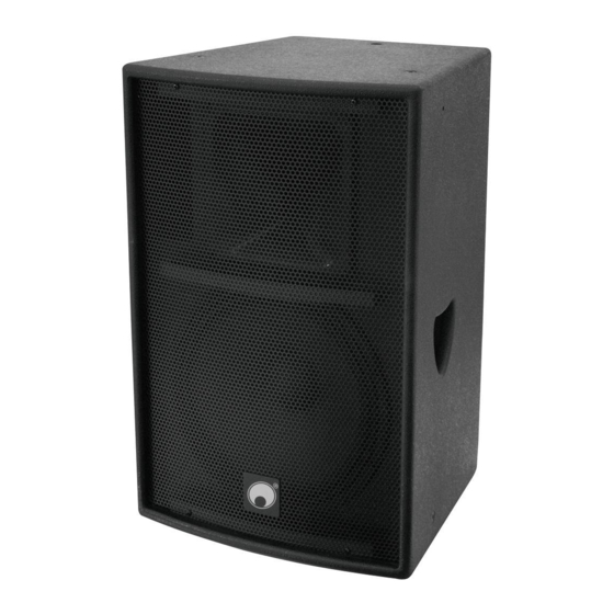
Speaker-systems
Für weiteren Gebrauch aufbewahren!
Keep this manual for future needs!
BEDIENUNGSANLEITUNG
BEDIENUNGSANLEITUNG
BEDIENUNGSANLEITUNG
BEDIENUNGSANLEITUNG
USER'S MANUAL
USER'S MANUAL
USER'S MANUAL
USER'S MANUAL
Active
AZ-212A
AZ-215A
©
Copyright
Nachdruck verboten!
Reproduction prohibited!
Advertisement
Table of Contents

Related Manuals for Omnitronic AZ-212A


Summary of Contents for Omnitronic AZ-212A
- Page 1 BEDIENUNGSANLEITUNG BEDIENUNGSANLEITUNG BEDIENUNGSANLEITUNG BEDIENUNGSANLEITUNG USER'S MANUAL USER'S MANUAL USER'S MANUAL USER'S MANUAL Active Speaker-systems AZ-212A AZ-215A © Copyright Für weiteren Gebrauch aufbewahren! Nachdruck verboten! Keep this manual for future needs! Reproduction prohibited!
-
Page 4: Table Of Contents
This user manual is valid for the article numbers 11038973, 11038975 Das neueste Update dieser Bedienungsanleitung finden Sie im Internet unter: You can find the latest update of this user manual in the Internet under: www.omnitronic.com 4/36 00038393.DOC, Version 1.0... -
Page 5: Einführung
- sich die letzte Version der Anleitung im Internet herunter laden EINFÜHRUNG Wir freuen uns, dass Sie sich für eine OMNITRONIC Lautsprecherbox entschieden haben. Wenn Sie nachfolgende Hinweise beachten, sind wir sicher, dass Sie lange Zeit Freude an Ihrem Kauf haben werden. - Page 6 LEBENSGEFAHR! Eine herabstürzende Lautsprecherbox kann tödliche Unfälle verursachen. Alle Sicherheits- hinweise in dieser Bedienungsanleitung müssen unbedingt eingehalten werden. Bitte beachten Sie, dass Boxen durch Bassschläge und Vibrationen verrutschen können. Außerdem stellen unbeabsichtigte Stöße ein erhöhtes Risiko dar. Deshalb muss die Box immer gegen Verrutschen gesichert oder der entsprechende Bereich abgesperrt werden.
-
Page 7: Bestimmungsgemäße Verwendung
so ist das Gerät sofort außer Betrieb zu nehmen und allpolig vom Netz zu trennen. Durch Metallteile hervorgerufene Fehlfunktionen und Kurzschlüsse können tödliche Verletzungen zur Folge haben. Bevor das Gerät eingeschaltet wird, müssen alle Fader und Lautstärkeregler auf "0" bzw. auf Minimum gestellt werden. - Page 8 Achten Sie bei der Montage, beim Abbau und bei der Durchführung von Servicearbeiten darauf, dass der Bereich unterhalb des Montageortes abgesperrt ist. ACHTUNG! Diese Lautsprecherbox darf niemals auf eine andere Lautsprecherbox aufgestellt werden - Lebensgefahr durch herabstürzende Boxen! ACHTUNG! Diese Lautsprecherbox darf nur durch erfahrenes Fachpersonal fliegend aufgehängt werden - Lebensgefahr durch herabstürzende Boxen! Diese Lautsprecherbox lässt sich als Topteil auf eine Bassbox (Satellitensystem), einen Boxenhochständer, ein geeignetes Stativ oder eine geeignete Wandhalterung montieren.
-
Page 9: Rechtliche Hinweise
Lärmbereich vor. Somit hat der Arbeitgeber Warnschilder aufzustellen und Gehörschutzmittel bereitzustellen. Die Arbeitnehmer haben diese zu benutzen. Bitte beachten Sie: OMNITRONIC haftet nicht für Schäden, die durch unsachgemäße Installation und übermäßige Lautstärken verursacht werden! Kleine Hörkunde Immer mehr junge Menschen leiden unter einem Hörverlust von 25 Dezibel und mehr, überwiegend... -
Page 10: Inbetriebnahme
Viele täuschen sich selbst mit der Vorstellung, dass Lärm etwas sei, woran man sich "gewöhne". Dass eine positive Einstellung zu einem bestimmten Geräusch physiologische Reaktionen abschwächen kann, soll nicht bestritten werden. Eine ganz andere Sache ist jedoch die schleichende Wirkung auf das Innenohr: die Überreizung und allmähliche Auflösung der Haarzellen des Cortischen Organs. -
Page 11: Line In
Belegung Klinkenstecker: Unsymmetrischer 6,35 mm Symmetrischer 6,35 mm Mono-Klinkenstecker tereo -Klinkenstecker Tip = Tip = Signal (+) Plus-Phase (+) Ring = Minus-Phase (-) Sleeve = Masse / Schirm Sleeve = Masse / Schirm Ring Sleeve Sleeve Zugentlastung Zugentlastung Um einen Stereo-Klinkenstecker unsymme- trisch an zu schließen, müssen Ring und Sleeve gebrückt werden. -
Page 12: Überkopfmontage
Einsatz der Lautsprecherboxen als Monitorboxen ist sorgfältig auf die Vermeidung von Rückkopplungen zu achten. Die Lautsprecherboxen eines PA-Systems plaziert man normalerweise links und rechts neben der Bühne. Stellen Sie die Box möglichst nicht auf der Bühne auf, sondern auf geeigneten Tischen oder Podesten davor. - Page 13 Die Installation muss immer mit einer zweiten, unabhängigen Aufhängung, z. B. einem geeigneten Fangnetz, erfolgen. Diese zweite Aufhängung muss so beschaffen und angebracht sein, dass im Fehlerfall der Hauptaufhängung kein Teil der Installation herabfallen kann. Während des Auf-, Um- und Abbaus ist der unnötige Aufenthalt im Bereich von Bewegungsflächen, auf Beleuchterbrücken, unter hochgelegenen Arbeitsplätzen sowie an sonstigen Gefahrbereichen verboten.
-
Page 14: Stacking
Bitte beachten Sie: Überprüfen Sie vor dem Eindrehen der Ringösen, ob der Zustand der Gewinde einwandfrei und frei von Verschmutzungen etc. ist. Drehen Sie die Ringösen in die Gewindeöffnungen der Lautsprecherbox. Die Ösen müssen dabei bis zum Anschlag eingedreht und handfest angezogen werden. Verwenden Sie niemals Werkzeug zum Festziehen. Hängen Sie die Schnellverschlussglied der Sicherungsseile in den dafür vorgesehenen Ringösen an der Lautsprecherbox ein. -
Page 15: Satellitensysteme
Satellitensysteme Wird eine Lautsprecherbox mit Einbauflansch auf eine Bassbox montiert, spricht man von einem Satellitensystem. Dabei muss jedoch unbedingt sichergestellt werden, dass das Satellitensystem über eine ausreichende Standfestigkeit verfügt. Die Grundfläche der Bassbox muss in Bezug auf das montierte Topteil immer ausreichend dimensioniert sein, damit ein Umstürzen verhindert wird. - Page 16 Die Gesamtmasse der Installation (=Gesamtgewicht aller Einzelteile) darf die zulässige Tragfähigkeit des Montageortes niemals überschreiten. Das Stativ muss außerhalb des Handbereichs von Personen installiert werden. Ein unbeabsichtiges Bewegen des Systems muss verhindert werden - auch unter Brandbedingungen! Der Installateur ist für die Einhaltung der vom Hersteller angegebenen Traglast, der Sicherheitsanforde- rungen sowie der Qualifikation eventueller Mitarbeiter verantwortlich.
-
Page 17: Montage Auf Einer Wandhalterung
Montage auf einer Wandhalterung Die Lautsprecherbox darf nur auf eine Wandhalterung montiert werden, wenn sie im Lieferzustand über eine entsprechende Aufnahmevorrichtung verfügt. Vergewissern Sie sich vor der Montage, dass die Montagefläche mindestens die 5-fache Punktbelastung der Belastbarkeit der Installation aushalten kann (z. B. 20 kg Belastbarkeit - 100 kg Punktbelastung). - Page 18 Beim Rückbau muss darauf geachtet werden, dass die Originalschrauben wieder in das Gewinde eingesetzt werden! Horizontale Aufhängung: Bitte beachten Sie: Die horizontale Installation muss immer über drei Ringösen erfolgen. Die Lautsprecherbox muss immer absolut plan (vertikaler Winkel 90° , horizontaler Winkel 0° ) installiert we rden. Vorgehensweise: Schritt 1: Lösen Sie die Imbusschrauben mit einem passenden Imbusschlüssel.
- Page 19 Gekippte Aufhängung: Bitte beachten Sie: Die gekippte Installation muss immer über zwei Ringösen an der Oberseite und eine an der Rückseite erfolgen. Die Lautsprecherbox darf maximal um 115° (vertikaler Winkel) bzw. 25° (horizon taler Winkel) gekippt werden. Clusters/Line Arrays: Verwenden Sie nur geprüfte Flyware namhafter Hersteller. Alle Hinweise in der Bedienungsanleitung der einelnen Komponenten müssen unbedingt eingehalten werden.
-
Page 20: Bedienung
BEDIENUNG Vergewissern Sie sich bitte, ob der Spannungswahlschalter auf die richtige Stromstärke gestellt ist bevor Sie die Netzleitung anschließen. Anschluss ans Netz Schließen Sie das Gerät über den Netzstecker ans Netz an. Die Belegung der Anschlussleitungen ist wie folgt: Leitung International Braun Außenleiter... -
Page 21: Sicherungswechsel
Schritt 4: Setzen Sie den Sicherungshalter wieder im Gehäuse ein. Wenn die Anschlussleitung dieses Gerätes beschädigt wird, muss sie durch eine besondere Anschluss- leitung ersetzt werden, die von Ihrem Fachhändler erhältlich ist. TECHNISCHE DATEN 11038973 AZ-212A 11038975 AZ-215A Spannungsversorgung: 230 V AC, 50 Hz ~ 230 V AC, 50 Hz ~ Gesamtanschlusswert (max.):... -
Page 22: Introduction
- download the latest version of the user manual from the Internet INTRODUCTION Thank you for having chosen an OMNITRONIC speaker-system. If you follow the instructions given in this manual, we are sure that you will enjoy this device for a long period of time. -
Page 23: Operating Determinations
Before the speaker-system is switched on all faders and volume controls have to be set to "0" or "min" position. CAUTION: Turn the amplifier on last and off first! HEALTH HAZARD! By operating speaker-systems with an amplifier, you can produce excessive sound pressure levels that may lead to permanent hearing loss. -
Page 24: Legal Instructions
This speaker system may only be installed on top of another speaker system if both systems are lashed up with each other via appropriate clamping belts and protected against flipping over. DANGER! This speaker system must only be suspended by experienced and trained persons - Danger to Life due to crashing speaker systems! If the original speaker system is equipped with an appropriate flange: This speaker system can be installed on top of a subwoofer (satellite system), on a speaker stand, an... -
Page 25: Information On Hearing Loss
This is why the entrepreneur has to set up warning signs and provide hearing protectors. The staff has to use these. Please note: OMNITRONIC cannot be made liable for damages caused by incorrect installations and excessive noise levels! Information on hearing loss More and more young people suffer from hearing loss of 25 decibel or more, mainly caused by loud music from portable cassette recorders and CD players or discotheques. -
Page 26: Mic In
In order to obtain highest sound quality, only use high-quality cables for connecting the devices. Make sure that the cables are properly fixed. Mic In Here, you can connect dynamic microphones via balanced microphone-cables. The microphone signals are connected via the XLR-socket. Occupation balanced XLR-connection: Balanced use with XLR connectors 1 = Ground / Shield... -
Page 27: Overhead Installation
Before installing the system, make sure that the installation area can hold a minimum point load of 5 times the system‘s load (e.g. weight 20 kg – point load 100 kg). The speaker-system must never be installed higher than 100 cm without secondary attachment. Install the desired number of speaker-systems in the room. - Page 28 DANGER TO LIFE! Please consider the valid standards and national regulation during the installation! The installation must only be carried out by an authorized dealer! The installation of the speaker-system has to be built and constructed in a way that it can hold 10 times the weight for 1 hour without any harming deformation.
-
Page 29: Stacking
The manufacturer cannot be made liable for damages caused by incorrect installations or insufficient safety precautions! Please note: Before installing the eye-bolts, make sure that the the thread is always in perfect condition and free from dirt etc. Install the eye-bolts in the threaded holes of the speaker-system. The eye-bolts must be tightened until stop position, hand-tight and without any tools. -
Page 30: Satellite-Systems
Please refer tot the instructions under Secondary attachment. Satellite-systems A satellite-system is a system where a speaker-system with flange is installed on top of a subwoofer. The satellite system must always provide enough stability. The subwoofer's base surface must always be sufficiently dimensioned in relation to the top speaker in order to prevent tilting over. -
Page 31: Installation On A Wall-Mounting
Before lifting or lowering the telescopic tubes, you must alway block a safety area around the stand or satellite system. This safety area must have a diameter of 1.5 times the maximum height. Lifted telescopic tubes always have to be secured with a secondary securing! The total weight of the installation (=total weight of all individual parts) must never exceed the maximum load of the installation area. -
Page 32: Suspended Installation
When installed on a wall-mounting, the speaker-system must always be secured with a safety bond. Before attaching the speaker-system, make sure that the installation area can hold a minimum point load of 5 times the installation‘s weight (e.g. 20 kg weight – 100 kg point load). The durability of the installation depends very much on the material used at the installation area (building material) such as wood, concrete, gas concrete, brick etc. - Page 33 Horizontal suspension: Please note: The horizontal installation must always be carried out via three eye-bolts and appropriate chains. The speaker-system must always be installed absolutely planar (vertical angle 90° , horizontal angle 0° ). Procedure: Step 1: Unscrew the allen screws with a suitable allen key. Step 2: Install the eye-bolts in the threaded holes of the speaker-system.
- Page 34 Tilted suspension: Please note: The tilted installation must always be carried out via two eye-bolts on top and one at the rear. The speaker- system can be tilted in a maximum vertical angle of 115° or maximum horizontal angle 25° . Clusters/Line Arrays: Only use certified Flyware of renowned manufacturers.
-
Page 35: Operation
OPERATION Make sure that the available voltage is not higher than stated on the voltage selector before you connect the power cord. Connection with the mains Connect the device to the mains with the power plug. The occupation of the connection cables is as follows: Cable International Brown... -
Page 36: Replacing The Fuse
Step 4: Replace the fuseholder in the housing. If the power supply cable of this device becomes damaged, it has to be replaced by a special power supply cable available at your dealer. TECHNICAL SPECIFICATIONS 11038973 AZ-212A 11038975 AZ-215A Power supply: 230 V AC, 50 Hz ~ 230 V AC, 50 Hz ~ Power consumption (max.):...
Need help?
Do you have a question about the AZ-212A and is the answer not in the manual?
Questions and answers