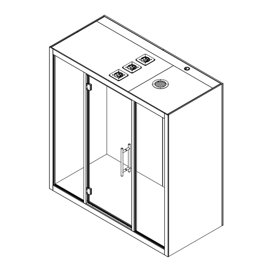
silen CHATBOX DUO Assembly Manual
Hide thumbs
Also See for CHATBOX DUO:
- Assembly manual (24 pages) ,
- Assembly manual (19 pages) ,
- Assembly manual (24 pages)
Advertisement
Quick Links
Advertisement

Subscribe to Our Youtube Channel
Related Manuals for silen CHATBOX DUO


Summary of Contents for silen CHATBOX DUO
- Page 1 CHATBOX DUO Assembly Manual...
- Page 2 Important safety informa�on Take photographs before and a�er opening the cardboard packages to document any damage caused during delivery. Minimum two persons required for the product assembly. 2 Person Assembly Approximate assembly �me is 1 h. Note! Assembly may take longer. Approx.
- Page 3 Product components A x1 C x1 B x2 D1 x1 D2 x1 D3 x1 E x2 G x2 I x2 F x2 H x1 M x2 l=2200mm L x2 l=2000mm K x4 l=550mm J x2 l=2039mm...
- Page 4 A�achments and Tools TOOLS: Allen key set Level Screwdriver Rache�ng straps 2pcs Suc�on cups min. 2x120mm 4pcs Rubber Mallet & Plas�c Block ATTACHMENTS: d x4 e x1 a x8 c x6 M5x40 M5x16 M6x30 Allen 4mm Allen 4mm Allen 5mm h x12 i x8 f x1...
- Page 5 1. Floor module Assembly 21 in / 535 mm 40 in / 1010 mm 21 in / 535 mm 4 in / 96 mm 37 in / 944 mm 37 in / 944 mm 4 in / 96 mm Place the Floor module (A) to desired loca�on of the Chatbox.
- Page 6 2. Side module Assembly 2 Person Assembly DANGER! a x4 Tip-Over Hazard! Note! Place highlighted aluminium profiles on front! Li� each of the Side modules (B) on top of the Floor module (A) and drive in screws “a” to secure the Side modules. Note! Assembly must be supported from the side to avoid tipping over before second Side module is attached.
- Page 7 3. Ceiling module Assembly b x4 2 Person Assembly Note! Place highlighted aluminium profiles on front! Step 1. Step 2. Step 1. Li� the Ceiling module (C) on top of the Side modules (B) and drive in screws “b” to secure the side modules. Step 2.
- Page 8 4. Rear Wall Panel Assembly 2 Person Assembly h x12 M5x70 h x12 Step 1. Li� the Rear wall panel (D1) on to the lath a�ached to Floor module (A). Step 2. Secure the Rear wall panel (D1) with screws “h” on marked loca�ons. Repeat step 1 and step 2 wit Rear wall panels (D2 &...
- Page 9 5. Rear Wall Trims Assembly 2 Person Assembly i x8 M3.5x35 Step 1. A�ach the Trims (E) To the rear wall panels (D1 & D3) with screws “i”. Step 1.
- Page 10 6. Rear Wall Covering Plate Assembly Step 1. A�ach the Covering plates (F) by placing them first on top of the Chatbox and then slowly let the magnets pull the side panel to it’s place. Step 2. Push the Covering plates (F) together un�l there is no gap in between. Step 1.
- Page 11 7. Front Glass Panel Assembly Don’t support on corner Step 1. Click in profiles (K) to the ceiling module using a rubber mallet and plas�c block to secure it. Step 2. - Li� the glass panel (G) into the top aluminum profile using suc�on cups, - Push the bo�om of the glass panel (G) towards the back of the cabin,...
- Page 12 8. Door Frame Assembly Don’t support on corner 180° BACK FRONT Note! To change the door handedness rotate the Door frame (H) 180°...
- Page 13 9. Front Glass Panel Adjustments Push the front glass panels (G) firmly towards the door frame un�l both panels are slid into the door frame profiles. Note! Make sure the side and floor module are perpendicular to each other...
- Page 14 10. Door Frame a�achments d x4 Drive in screws “d” to a�ach the Door frame (H) to the Chatbox Note! Door must be in “open” position for assembly. d x4 M6x30 Allen 5mm...
- Page 15 11. Profile Assembly Step 1. Click in profiles (J) to the side modules using a rubber mallet and plas�c block to secure it. Step 2. repeat the process with profiles (K) on Floor module.
- Page 16 12. Door Handle Assembly Step1. Place the Door handle “e” on the Door glass (H) and secure it with the provid- e x1 ed handle set a�achments. Step 2. Place the second half of the handle on top of the a�achments and secure the bolts with an allen key.
- Page 17 13. Door Threshold Assembly Step1. Remove protec�on tape from deco- f x1 ra�ve door threshold “f” Step 2. A�ach threshold with glue covered side to door frame (H).
- Page 18 14. Horizontal Covering Trim Assembly A�ach covering trims (L) to the Floor and Ceiling modules (A & C). Parts are secured with magnets which are preinstalled to modules.
- Page 19 15. Ver�cal Covering Trim Assembly c x6 Step 1. Step 2. Step 1. A�ach the Covering trims (M) to Covering trims (L) with preinstalled pins. Step 2. Secure the Covering trims (M) to Side module (B) with preinstalled brackets and screws “c”.
- Page 20 16. Connec�ng eletrical fi�ngs g x1 Remove the Cover plate from Ceiling module - Powercord connection (C) to expose electrical fi�ngs. Connect - Side panel (table socket) connection Power chord “g” and return Cover plate.
- Page 21 Optional. Power chord posi�oning...
- Page 22 17. Covering plate Assembly A�ach the Covering plates (I) by placing them first on top of the Chatbox and then slowly let the magnets pull the side panel to it’s place.
Need help?
Do you have a question about the CHATBOX DUO and is the answer not in the manual?
Questions and answers