Advertisement
Quick Links
Advertisement

Subscribe to Our Youtube Channel
Related Manuals for silen CHATBOX Quattro


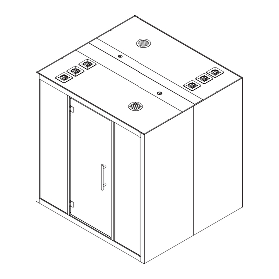
Summary of Contents for silen CHATBOX Quattro
- Page 1 CHATBOX Qua�ro Assembly Manual...
-
Page 2: Important Safety Informa�On
Important safety informa�on Take photographs before and a�er opening the cardboard packages to document any damage caused during delivery. Minimum two persons required for the product assembly. 2 Person Assembly Approximate assembly �me is 1 h. Note! Assembly may take longer. Approx. -
Page 3: Product Components
Product components F x1 A1 x1 A2 x1 D x3 E x2 B1 x2 B2 x2 G x4 C1 x1 C2 x1 H x4 l=546mm I x4 l=1994mm J x2 l=2091mm K x2 l=2200mm L x2 l=2000mm... - Page 4 Tools & A�achments TOOLS: Rubber Mallet & Plas�c Block Rache�ng straps 2pcs ATTACHMENTS: Allen key set c x6 d x2 a x9 b x16 Suc�on cups min. 2x120mm 4pcs M4.5x45 M8x30 TX15 4200mm e x2 f x4 g x1 h x1 i x2 M5x30 2085mm...
- Page 5 1. Floor Module Leveling 21 in / 533 mm 20 in / 506 mm 20 in / 506 mm 21 in / 533 mm 4 in / 93 mm 37 in / 947 mm 37 in / 947 mm 4 in / 93 mm Place the Floor module (A1) to desired loca�on of the Chatbox.
- Page 6 2. Floor Module Leveling 21 in / 533 mm 20 in / 506 mm 20 in / 506 mm 21 in / 533 mm 4 in / 93 mm 37 in / 947 mm 37 in / 947 mm 4 in / 93 mm Place the Floor module (A2) to desired loca�on of the Chatbox.
- Page 7 3. Floor module Assembly 2 Person Assembly a x3 Place pins “a” in the back side of the floormodule (A1) and push both modules (A1 & A2) together. Note! Make sure both modules are leveled to the same height, if not repeat instructions from page 4 & 5 and readjust the modules REPEAT PREVIOUS STEPS UNTIL LEVEL...
- Page 8 4. Side Module Assembly 2 Person Assembly DANGER! Tip-Over Hazard! Note! Place highlighted aluminium profiles on front! FRONT MUST b x2 BE LEVEL! Li� the Side module (B1) on top of the Floor module (A1) and make sure the aluminium profiles highlighted on the scheme above are level with each other.
- Page 9 5. Side Module Assembly 2 Person Assembly DANGER! Tip-Over Hazard! Note! Place highlighted aluminium profiles on front! c x3 A�ach the pins “a” to the side module (B) and li� the side module (B2) FRONT MUST on top of the Floor module (A2). Then push the side modules (B1 & B2) BE LEVEL! together un�l the aluminium profiles highlighted on the scheme above are level with each other.
- Page 10 6. Side Module Assembly 2 Person Assembly DANGER! Tip-Over Hazard! c x3 b x2 Secure the side modules (B1 & B2) using part “c” and �ghten them with 10mm . Then fix the side module (B1) with screws “b” while making wrench sure the aluminium profiles highlighted on the scheme above are level with each other.
- Page 11 7. Side Module Assembly 2 Person Assembly DANGER! Tip-Over Hazard! c x3 b x2 b x2 a x3 To finish the side module assembly, repeat steps from page 7 - 9: Page 7: Li� the Side module (B2) on top of the Floor module (A1) and c x3 drive in screws “b”...
- Page 12 8. Ceiling Module Assembly b x4 2 Person Assembly Note! Place highlighted aluminium profiles on front! Step 1. Step 2. Step 1. Li� the Ceiling module (C1) on top d x2 Step 3. of the Side modules (B1 & B2) and drive in screws “b”...
- Page 13 9. Ceiling Module Assembly b x4 2 Person Assembly Note! Place highlighted aluminium profiles on front! Step 1. Step 2. Step 1. A�ach gasket “d” to the inner edge d x2 Step 3. of the ceiling module (C2). Make sure the gasket is covering the en�re lenght of the ceiling module (C2).
- Page 14 10. Back Glass Panel Assembly Don’t support on corner Step 1. Click in profile (I) to the ceiling module (C2) using a rubber mallet and plas�c block to secure Step 2. - Li� the glass panel (D) into the top aluminum profile using suc�on cups, - Push the bo�om of the glass panel (D) towards the back of the cabin,...
- Page 15 11. Back Glass Panel Assembly Don’t support on corner Step 1. Carefully clean the visible edges of previously installed glass panels with solvent based solu�on to remove any residue. Remove the glue covering strip from glass-glass seal “e” from only one side and a�ach it to the edge of glass panel in full length.
- Page 16 12. Back Glass Panel Assembly Don’t support on corner Step 1. Step 1. Remove the remaining glue covering strips from previ- ously a�ached glass-glass seals “e”, Step 2. A�ach four suc�on cups on the side glass panels (as shown on schema�c). Place ratche�ng straps between the top and bo�om suc�on cups and �ghten un�l all panels are fixed to the glass-glass seals while making sure the glass panels are on the same plane to one another.
- Page 17 13. Profile Assembly Step 1. Click in profiles (J) to the side modules using a rubber mallet and plas�c block to secure it. Step 2. repeat the process with profiles (I) on Floor module. Step 2.
- Page 18 14. Front Glass Panel Assembly Don’t support on corner Step 1. Click in profiles (H) to the ceiling module using a rubber mallet and plas�c block to secure it. Step 2. - Li� the glass panel (E) into the top aluminum profile using suc�on cups, - Push the bo�om of the glass panel (E) towards the back of the...
- Page 19 15. Door Frame Assembly Don’t support on corner 180° FRONT Note! To change the door handedness rotate the Door frame (H) 180°...
- Page 20 16. Front Glass Panel Adjustments Push the front glass panels (E) firmly towards the door frame un�l both panels are slid into the door frame profiles. Note! Make sure the side and floor module are perpendicular to each other...
- Page 21 17. Door Frame a�achments f x4 Drive in screws “f” to a�ach the Door frame (H) to the Chatbox Note! Door must be in “open” position for assembly. f x4 M5x30 Allen 5mm...
- Page 22 18. Profile Assembly Step 1. Click in profiles (J) to the side modules using a rubber mallet and plas�c block to secure it. Step 2. repeat the process with profiles (H) on Floor module.
- Page 23 19. Door Handle Assembly Step1. Place the Door handle “g” on the g x1 Door glass (F) and secure it with the provid- ed handle set a�achments. Step 2. Place the second half of the handle on top of the a�achments and secure the bolts with an allen key.
- Page 24 20. Door Threshold Assembly Step1. Remove protec�on tape from deco- h x1 ra�ve door threshold “h” Step 2. A�ach threshold with glue covered side to door frame (F).
- Page 25 21. Covering Trim Assembly A�ach covering trims (L) on the front/back side of floor modules (A1 & A2) and ceiling modules (C1 & C2). A�ach covering trims (K) on the front/back side of side modules (B1 & B2) and connect them with pins a�ached to trims (L)
- Page 26 22. Connec�ng eletrical fi�ngs i x2 Remove the Cover plate from Ceiling modules (C1 - Powercord connection & C2) to expose electrical fi�ngs. Connect Power - Side panel (table socket) connection chord “i” and return Cover plate.
- Page 27 Optional. Power chord posi�oning...
- Page 28 23. Covering plate Assembly A�ach the Covering plates (G) by placing them first on top of the Chatbox and then slowly let the magnets pull the side panel to it’s place.
Need help?
Do you have a question about the CHATBOX Quattro and is the answer not in the manual?
Questions and answers