Advertisement
Quick Links
Advertisement

Related Manuals for Technika T150EG95U


Summary of Contents for Technika T150EG95U
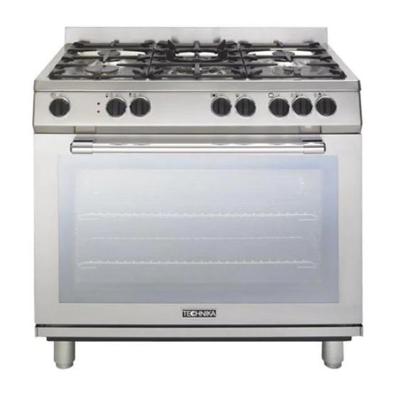
- Page 1 A GUIDE TO USE, INSTALLATION AND REGULATION OF COOKERS MODEL: T150EG95U...
- Page 2 The appliance was designed and made in accordance with the European standards listed below: => EN 30-1-1, EN 30-2-1 and EN 437 plus subsequent amendments (gas) => EN 60 335-1 and EN 60 335-2-6 (electrical) plus relative amendments The appliance complies with the prescriptions of the European Directives as below: =>...
-
Page 3: Table Of Contents
ASSISTANCE AND SPARE PARTS Before this appliance left the factory it was tested and fine-tuned by specialised expert personnel in order to guarantee its best functioning results. Any subsequent repairs or adjustments that may be necessary must be done with the maximum of care and attention by qualified personnel. -
Page 4: Important Notes And Precautions For Use
IMPORTANT NOTES AND PRECAUTIONS FOR USE removed from the outer surfaces and You have purchased one of our the various inner parts, thoroughly products for which we thank you. We check that the appliance is in perfect are confident that this new appliance, condition. - Page 5 IMPORTANT NOTES AND PRECAUTIONS FOR USE • The oven door glass and the will allow the protective coating on accessible parts will become hot the interior of the oven to be burnt when in use. To avoid burns and off and dissipate the associated scalds young children should be smells.
- Page 6 IMPORTANT NOTES AND PRECAUTIONS FOR USE • The appliance is not intended to be • Switch off the electrical supply before operated by means of an external you start cleaning or servicing the timer or separate remote-control appliance. system • In the case of a failure or malfunction, •...
-
Page 7: Description Of The Appliance
DESCRIPTION OF THE APPLIANCE GENERAL The cooker is fitted with a gas hob. Each knob on the front panel has a diagram printed above it showing to which burner it refers. The combination of the different sized burners offers the possibility of various types of cooking. Our cookers are fitted with a electric oven and an electric gril The oven walls of the two cavity, are fitted with various... - Page 8 DESCRIPTION OF THE APPLIANCE DESCRIPTION OF THE CONTROLS HOB GAS BURNER KNOB (A) By turning the knob counterclockwise, the following symbols appear: • = Closed position = “Full on” position = “Reduced rate” position OVEN THERMOSTAT KNOB (B) By turning the oven knob clockwise you will find the different oven temperature values (from 50°C to Maxi).
-
Page 9: Instructions For The User
INSTRUCTIONS FOR THE USER HOB: GENERAL NOTES ON SAFETY ABNORMAL OPERATION Any of the following are considered to be abnormal • When using the burners, do not leave the appliance unsupervised. Ensure that children and the infirm operation and may require servicing: do not play with the appliance. - Page 10 INSTRUCTIONS FOR THE USER OVEN: GENERAL SAFETY INSTRUCTIONS • Do not leave the oven unsupervised during use. Ensure that children and the infirm do not play with the appliance. • DO NOT SPRAY AEROSOLS IN THE VICINTY OF THIS APPLIANCE WHILE IT IS IN OPERATION. •...
- Page 11 INSTRUCTIONS FOR THE USER HOW TO USE THE MULTIFUNCTION OVEN CONVETIONAL GRILL COOKING Turn the selector knob to the symbol and set the DEFROSTING AT ROOM TEMPERATURE thermostat to the desired temperature. Selecting this Turn the selector knob to the symbol and place the function the top central heating element turns on and food you want to defrost inside the oven.
- Page 12 INSTRUCTIONS FOR THE USER USEFUL COOKING TIPS Meat: • If, when cooking meat, the time needed is more than 40 minutes, turn the oven off 10 minutes before Cakes and bread: the end of cooking time to exploit the residual heat •...
- Page 13 INSTRUCTIONS FOR THE USER NATURAL CONVECTION AND FORCED CONVECTION - COOKING / BAKING TIMETABLE COOKING BY NATURAL COOKING BY FORCED Position of the CONVECTION CONVECTION (with fan) Weight FOODS oven shelf from Temperatures Cooking time Temperatures Cooking time the bottom in °C in min in °C...
- Page 14 INSTRUCTIONS FOR THE USER CLEANING AND MAINTENANCE OVEN CAVITY Do not spray or wash the thermostat bulb with acid • Prior to any maintenance work or cleaning, based products (check the product label before use). disconnect the appliance from the electricity mains.
- Page 15 INSTRUCTIONS FOR THE USER OVEN SIDEWALL GRIDS (fig. 11) REPLACING THE OVEN LAMP To allow for a better cleaning of the side grids, you can Ensure the appliance is switched off before replacing extract them this way: the lamp to avoid the possibility of electric shock.. 1.
-
Page 16: Instructions For The Installer
INSTRUCTIONS FOR THE INSTALLER TECHNICAL INFORMATION of mechanical ventilation where present. UNPACKING YOUR COOKER • The installations, conversions and maintenance • Once the packaging has been removed, thoroughly operations listed in this part must only be carried out check that the appliance is in perfect condition. If you by authorised personnel. - Page 17 INSTRUCTIONS FOR THE INSTALLER POSITION (fig. 14) LEVELLING THE COOKER The appliance should be positioned in good light and • Adjustable feet, This model has very slight free from draughts. Any adjoining wall surface situated adjustable feet which can go from a heght of 900 - within 200 mm from the edge of any hob burner 920mm It has full plinths on both sides.(fig.15) must be a suitable non-combustible material for a...
- Page 18 INSTRUCTIONS FOR THE INSTALLER INSTRUCTION FOR STABILIZING THE COOKER The installation of the brackets provided is for safety reasons and must be installed as indicated below. EQUIPMENT QUANTITY n°2 n°2 n°4 WARNING: In order to prevent the cooker tipping forwards in the event of children standing on the oven door or where users put extreme weight on the door when in open position, the stabilising means must be installed by the installer.
- Page 19 INSTRUCTIONS FOR THE INSTALLER (fig.2) Mark it the same distance, (X) on back wall. (fig.3) Drill two holes in the wall for each bracket according to the fig. 2 and fix the bracket. (fig.4) Push back the cooker against the wall. IMPORTANT: After fitting the stablising brackets and pushing the cooker into position, check that the cooker does not tilt forward or sideways Hose Restraint Chain...
- Page 20 INSTRUCTIONS FOR THE INSTALLER hazardous overheating. ELECTRICAL CONNECTION When connecting directly to the mains: The electrical connection must be carried out in • If the appliance is not fitted with a supply cord accordance with the current standards and laws in and a plug, or with other means for disconnection force.
- Page 21 INSTRUCTIONS FOR THE INSTALLER GAS CONNECTION Installation using flexible connection As an option, the cooker may be installed with a This appliance shall be installed only by authorised flexible connection hose, which complies with AS/ personnel and in accordance with the manufacturer’s NZS 1869 (AGA Approved), 10 mm ID, class B or installation instructions, local gas fitting regulations, D, Minimum 1000 mm - Maximum 1200 mm, as an...
- Page 22 INSTRUCTIONS FOR THE INSTALLER ADJUSTMENTS CONVERSIONS • Always disconnect the appliance from REPLACING THE INJECTORS the electricity supply before making any Our burners can be adapted to different types of adjustment. gas by simply installing the injectors suitable for • All seal must be replaced by the technician the gas you want to use.
- Page 23 INSTRUCTIONS FOR THE INSTALLER MAINTENANCE Prior to any maintenance work or changing parts, disconnect the appliance from the gas and electricity power sources. Warning: Servicing should be carried out only by authorised personnel. REPLACING THE TAPS Proceed in the following way when replacing a tap: •...
-
Page 24: Troubleshooting
INSTRUCTIONS FOR THE INSTALLER REPLACING THE ELECTRICAL COMPONENTS CHANGING THE FLEXIBLE GAS HOSE • The rear protection will have to be removed in order In order to guarantee that the gas hose is always in to change the electrical heating elements, lamp excellent condition we strongly recommend changing holder, terminal board and power cable. -
Page 25: Technical Features
TECHNICAL FEATURES BURNER DISPOSITION AND HOB BURNER TECHNICAL DATA TABLE Diameter Operating Rating Burner Denomination Injectors Sabaf Pressure Kpa Mj/H 1/100 Mm U-LPG 2.75 10.0 Large Natural 1.00 10.0 U-LPG 2.75 Medium Natural 1.00 U-LPG 2.75 Small Natural 1.00 U-LPG 2.75 14.6 Natural... - Page 28 SPACE FOR DATA LABEL...
Need help?
Do you have a question about the T150EG95U and is the answer not in the manual?
Questions and answers