
Related Manuals for Digital Watchdog PowerPix DWC-B6361WTIR


Summary of Contents for Digital Watchdog PowerPix DWC-B6361WTIR
- Page 1 IR Bullet Camera DWC-B6361WTIR ABOUT MANUAL Before installing and using the camera, please read this manual carefully. Be sure to keep it handy for future reference. 12132013...
- Page 2 PRECAUTIONS Do not open or modify. Do not open the case except during maintenence and installation, for it may be dangerous and can cause damages. Do not put objects into the unit. Keep metal objects and flammable substances from entering the camera. It can cause fire, short-circuits, or other damages.
- Page 3 Table of Contents TABLE OF CONTENTS Introduction Features Parts and Descriptions Dimensions Installation Inside the Box Mount Installation Instructions Connecting to Monitors Control Board Adjusting the Camera Angle Module OSD Menu 12-20 Troubleshooting Warranty Information 22-23 Specifications 24-25...
- Page 4 FEATURES* FEATURES* 1/3” 760H CMOS Sensor Chip (760 Horizontal Pixels) 690 TV Lines 2.8~12mm Varifocal Auto Iris Lens 100ft Range IR with Intelligent Camera Sync TDN (True Day & Night) with IR Cut Filter WDR (Wide Dynamic Range) 2D DNR (2D Digital Noise Reduction) Smear Cancelation AGC / AWB Easy Icon Driven OSD Menu with Built-in Joystick...
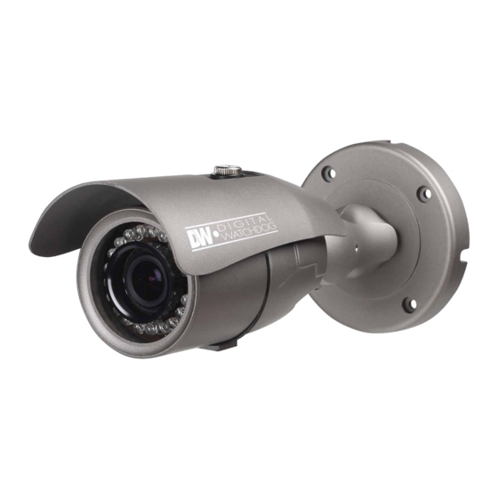
- Page 5 PARTS & DESCRIPTION* IR & Lens Module Mounting Bracket Front Case Camera Module OSD Joystick Controller Sunshield Adjusting Screws Sunshiled Cover Set Screw...
- Page 6 DIMENSIONS IN MILLIMETERS (IN)* 234.5 9.23 112.0 4.41 94.0 3.70 4.2 0.17 78.0 3.07 61.5 2.42...
- Page 7 INSIDE THE BOX* Included with Bullet Camera: User Manual Mounting Template 4 Machine Screws and 4 Dry Wall Anchors L-Key Bullet Camera DWC-B6361WTIR ABOUT MANUAL Before installing and using the camera, please read this manual carefully. Be sure to keep it handy for future reference. 08122013...
- Page 8 INSTALLATION INSTRUCTIONS* 1. Using the mounting template or your own camera, mark and drill the necessary holes to mount the bracket to a wall or ceiling. 2. Pull all necessary wires through and make the proper connections. 3. Use the four (4) mounting screws to install the camera on the wall or ceiling.
- Page 9 CONNECTING TO MONITORS* Use the diagram below to connect to a Monitor or CRT Monitor properly. 12VDC/24VAC CCTV Monitor Left Right Down Second Video Output Monitor Power Connection - 12VDC/24VAC Dual Voltage (Auto Polarity Detection and Protection) All cameras are equipped with a second video output for on-site configuration.
- Page 10 CONTROL BOARD* Secondary Connector: Video Output Connector for On-Site Configuration Joystick: Controls the OSD menu. Remove the camera’s lens cover by rotating it counter-clockwise. Use the Joystick to control the camera’s OSD options.
- Page 11 ADJUSTING THE CAMERA ANGLE* CAUTION : Do not rotate more than 360 Do not unnecessarily twist too many times.
- Page 12 MODULE OSD MENU* EXPOSURE COLOR DAY & NIGHT LENS WB MODE D&N MODE MANUAL / DC ATW / INDOOR / OUTDOOR AUTO / COLOR / ETX. BRIGHTNESS COLOR GAIN EXIT JUMP 1 ~ 10 1 ~ 10 SAVE & EXIT / EXIT EXIT JUMP LOW / MIDDLE / HIGH SAVE &...
- Page 13 EXPOSURE LENS Manual mode supports the fixed board lens or the Manual manual iris lens. DC mode supports the auto-iris varifocal lens. BRIGHTNESS Adjust the camera’s brightness from 0~10. The higher the number, the brighter the image will appear.
- Page 14 EXPOSURE WDR (Wide Dynamic Range) Enables the camera to capture clear images even when there are both very bright and very dark areas in the camera’s field of view. Select from the following options: LOW / MIDDLE (Default) / HIGH. WDR OFF WDR ON AGC (Auto Gain Control)
- Page 15 COLOR WB MODE Set as the camera’s default value. Auto Tracking White Balance Control mode compensates for color temperature changes between 2500K and 9500K. OUTDOOR Select this option if the camera is to be mounted ouside in an open area. INDOOR Select this option if the camera is to be mounted inside a closed area.
- Page 16 DAY & NIGHT D&N MODE AUTO In AUTO mode, camera switches between day and night automatically depending on light level. COLOR If COLOR is selected, camera always stays in day/color mode. For best IR LEDs performance, select this option as default. FUNCTION CONTRAST 1~10...
- Page 17 FUNCTION MIRROR The mirror option allows you to flip the camera’s image horizontally and vertically to adjust the camera’s view after installation. Chose from the following options: NONE / H / V / H, V. V - Flip- turns the camera upside down. H - Flip- Mirors the camera horizonatll.
- Page 18 SETUP WHITE LEVEL Adjust the camera’s White Levels from 1 ~ 10. The higher the number, the stronger white colors in the camera’s Field of View will appear. The camera is set by default to the optimal White Level and therefore it is recommended not to change the original settings.
- Page 19 SETUP BURST Setting the color signal level value from 1 to 10. The camera is set by default to the optimal burst level and therefore it is recommended not to change the original settings. OSD BG You can add a dark background behind the OSD to better view the OSD options when the camera’s image is too bright and the OSD text is not seen properly.
- Page 20 EXIT EXIT SAVE Exit the OSD menu after saving the recent changes. RESET Exit the OSD menu adter resetting the camera to its default settings.
- Page 21 TROUBLESHOOTING Before sending your camera for repair, check the following or contact our technical specialist. FOR NO VIDEO Check the coaxial cable and make sure it is connected securely. Check the lens’ iris adjustment at the camera’s OSD menu. Check the power supply and make sure the camera has the proper voltage and current.
- Page 22 WARRANTY INFORMATION* Digital Watchdog (referred to as “the Warrantor”) warrants the Digital Watchdog Camera against defects in materials or workmanship as follows: LABOR: For the initial five (5) years and one (1) year on IR LED from the original purchase date, if the camera is determined to be defective, the Warrantor will repair or replace the unit with a new or refurbished product at its option at no charge.
- Page 23 This warranty gives you specific legal rights, and you may also have other rights that vary from state-to-state. If the problem is not handled to your satisfaction, then write to the following address: Digital Watchdog, Inc. ATTN: RMA Department 5436 W. Crenshaw Street...
- Page 24 SPECIFICATIONS* VIDEO Image Sensor 760H CMOS Total Pixels 756(H) X 504(V) Scanning System 2 : 1 Interlace Frequency 15.734KHz (H), 59.95Hz (V) Synchronization Internal Horizontal Resolution 690TV Lines Minimum Illumination F1.2 (30IRE): 0.0 Lux S/N Ratio 58dB (AGC off) Video Output CVBS: 1.0Vp-p / 75 Ω...
- Page 25 OPERATIONAL Day and Night AUTO/ COLOR/ EXT Mirror NONE/ H/ V/ H,V Contrast 1~10 Sharpness 1 ~ 10 White Level 1~10 ENVIRONMENTAL Operating Temperature C ~ 50 C (14 F ~ 122 Operating Humidity Less than 90% (Non-Condensing) IP Rating IP66 (Protects against dust and high pressure water.) ELECTRICAL...
- Page 26 MEMO*...
- Page 27 MEMO*...
- Page 28 5436 W Crenshaw St. Tampa, FL 33634 Tel : 866-446-3595 / 813-888-9555 Fax : 813-888-9262 www.Digital-Watchdog.com technicalsupport@dwcc.tv Technical Support Hours : Monday-Friday 9:00am to 8:00pm EST...
Need help?
Do you have a question about the PowerPix DWC-B6361WTIR and is the answer not in the manual?
Questions and answers