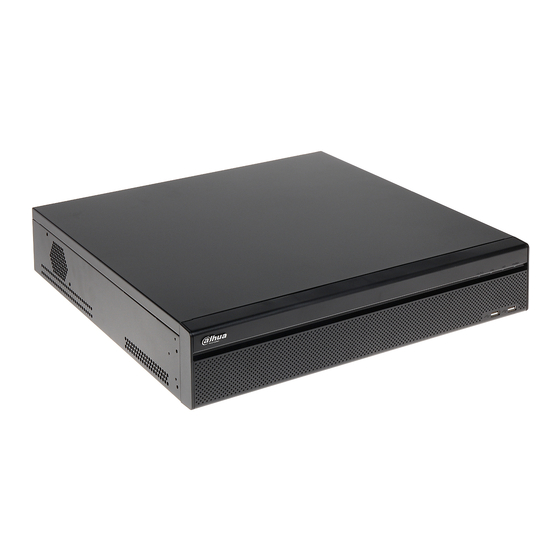
Page 2
Cybersecurity Recommendations Mandatory actions to be taken towards cybersecurity 1. Change Passwords and Use Strong Passwords: The number one reason systems get “hacked” is due to having weak or default passwords. It is recommended to change default passwords immediately and choose a strong password whenever possible.
Page 3
Those using SmartPSS to view their system and on a computer that is used by multiple people should disable auto-login. This adds a layer of security to prevent users without the appropriate credentials from accessing the system. 8. Use a Different Username and Password for SmartPSS: In the event that your social media, bank, email, etc.
Page 4
Regulatory Information FCC Information CAUTION Changes or modifications not expressly approved by the party responsible for compliance could void the user's authority to operate the equipment. FCC conditions: This device complies with part 15 of the FCC Rules. Operation is subject to the following two conditions: ...
Table of Contents Features and Specifications ....................... 1 Overview ............................1 Features ............................1 Specifications ..........................2 1.3.1 NVR608-4KS2 Series ......................2 1.3.2 NVR616-4KS2 Series ......................5 1.3.3 NVR724-256 Series ......................7 Product Structure..........................11 Checking the Components ....................... 11 Front Panel and Rear Panel .....................
Page 6
3.4.6 Schedule ..........................52 3.4.6.1 Schedule Record ......................52 3.4.6.2 Schedule Snapshot ....................56 3.4.6.3 Record Control ......................58 3.4.6.4 Record Info ........................59 Remote Device ........................... 60 3.5.1 Remote Device Connection ....................60 3.5.1.1 Change IP address ....................60 3.5.1.2 IP Export ........................
Page 7
3.6.6.3 Custom Split ........................ 89 3.6.7 Fisheye ..........................91 3.6.7.1 Fisheye de-warp during preview interface .............. 91 3.6.7.2 Fish eye de-warp during playback ................93 3.6.8 Split Track ..........................93 3.6.9 Smart Track .......................... 94 3.6.10 Real-Time Spot Temperature Measurement ............... 95 3.6.11 Panoramic+PTZ Camera Preview ..................
Page 14
Foreword General This user’s manual (hereinafter referred to be "the Manual") introduces the functions and operations of the Network Video Recorder (NVR) devices (hereinafter referred to be "the Device"). Safety Instructions The following categorized signal words with defined meaning might appear in the Manual.
Page 15
About the Manual The Manual is for reference only. If there is inconsistency between the Manual and the actual product, the actual product shall prevail. We are not liable for any loss caused by the operations that do not comply with the ...
Page 16
Important Safeguards and Warnings The following description is the correct application method of the device. Read the manual carefully before use to prevent danger and property loss. Strictly conform to the manual during application and keep it properly after reading. Operating Requirement Install the PoE front-end device indoors.
1 Features and Specifications 1.1 Overview This series NVR is a high performance network video recorder. This series product support local preview, multiple-window display, recorded file local storage, remote control and mouse shortcut menu operation, and remote management and control function. This series product supports centre storage, front-end storage and client-end storage.
• Through network, sending audio/video data compressed by IPC or NVS to client-ends, then the data will be decompressed and display. • Support max 128 connections at the same time. Network • Transmit audio/video data by HTTP, TCP, UDP, MULTICAST, Monitor RTP/RTCP and etc.
Page 19
Model NVR608-32- NVR608-6 NVR608-128- NVR608R-6 NVR608R-128- 4KS2 4-4KS2 4KS2 4-4KS2 4KS2 Para Input meter Audio 1-ch MIC bidirectional talk audio output Output Audio G.711a Compressi Standard Video Video 32-ch 64-ch 128-ch 64-ch network 128-ch Para Input network network network compression network meter compression...
Page 20
Model NVR608-32- NVR608-6 NVR608-128- NVR608R-6 NVR608R-128- 4KS2 4-4KS2 4KS2 4-4KS2 4KS2 Mode Network SNMP/FTP/ISCSI/UPNP Protocol SATA Port eSATA Port RS232 Port 1 RS232 port. To debug and transmit COM data. RS485 Port 1 RS485 port. To control peripheral PTZ and etc. Support various protocols. USB Port 2 USB 2.0 ports and 2 USB3.0 ports.
Dimensions (L×W×H)(With 735*660*465mm Packages) Weight 17.45Kg(No HDD) Installation Mode Rack/desktop 1.3.3 NVR724-256 Series Specifications NVR724-256 Main Processor Industrial X86 multiple-core processor Operation System Embedded LINUX system Power Support hot swap Redundant dual ball bearing fan MTBF>100 thousand hours Support online replacement. System Memory 8GB Server-level...
Page 24
Independent HDD bracket, support HDD hot swap. HDD Installation Disk Array Enclosure/Backu eSATA port p Port HDD Backup Support global hotspare HDD HDD Mode One HDD/RAID0/RAID1/RAID5 Non-working HDD adopts hibernation function. It is suitable to HDD Manager guarantee sound ventilation, lower power consumption and enhance HDD life span.
Page 25
Enable or disable alarm input channel Manual Alarm Control Simulate alarm signal to specific alarm output channel. Alarm Input 4-channel alarm input (NO/NC) Alarm Output 4-channel relay output Alarm Relay 30VDC 2A,125VAC 1A(activation output) 2 USB 2.0 ports, USB port 2 USB 3.0 ports Network Amount 4 100/1000Mbps Ethetnet ports...
Page 26
Dimensions 545mm(with the LCD length)×482.6mm(With ear)×175mm (L×W×H) (4U case) 514mm ( without the LCD length ) ×482.6mm ( With ear ) ×175mm(4U case) 493.5mm ( without the LCD length ) ×480mm ( Without ear ) ×175mm 4U case) Weight 27Kg(No package materials, no HDD) Installation Mode Standard 19-inch rack installation Rack/desktop...
The following front panel and rear panel figures are for reference only. The actual product shall prevail. 2.2.1 NVR608-4KS2 Series The NVR608-32-4KS2 front panel is shown as in Figure 2-1. Figure 2-1 Please refer to the following sheet for front panel button information.
Icon Name Function HDD status indicator The blue light is on when the HDD is malfunction. light Network status indicator The blue light is on when the network connection is light abnormal. POWER Power status indicator light The blue light is on when the power connection is USB2.0 port Connect to peripheral USB 2.0 storage device, mouse, burner and etc.
Page 29
Name Function Power button Press it once to turn on the device. Press it for a long time to turn off the device. (Usually we do not recommend). Press power button for a long time or pull out the power cable may result in device auto restart.
USB port 16 HDD slot After you remove the front panel, you can see there are 16 HDDs. From the left to the right and from the top to the bottom, it ranges from 1~4, 5~8, 9~12, 13~16. See Figure 2-5. You can see there are two indicator lights on the HDD bracket.
: The read-write indicator light is at the bottom. The blue light flashes when system is reading or writing the data. Figure 2-7 2.3 Rear Panel 2.3.1 NVR608-4KS2 Series The NVR608-32-4KS2 series rear panel is shown as in Figure 2-8.
Page 32
Figure 2-8 The NVR608-64-4KS2/NVR608-128-4KS2 general series rear panel is shown as in Figure 2-9. Figure 2-9 The NVR608-64-4KS2/NVR608-128-4KS2 redundant power series rear panel is shown as in Figure 2-10. Figure 2-10 Please refer to the following sheet for detailed information. Function Function Power socket...
NVR608-4K: USB 3.0 port 2.0 port. NVR608-4KS2: USB 3.0 port eSATA port 2.3.2 NVR616-4KS2 Series The general series rear panel of NVR616-4KS2 is shown as in Figure 2-11. Figure 2-11 The redundant power series rear panel of NVR616-4KS2 is shown as in Figure 2-12. Figure 2-12 Please refer to the following sheet for rear detailed information.
Name Name 1000M fiber port Network port HDMI port RS232 port Video VGA output Audio output Audio input USB3.0 port USB3.0 port eSATA port SAS extension port Alarm input/output/RS485 port HDMI port (The HD decode card is not the default accessory. Please purchase if you want to use) 2.3.3...
Figure 2-14 Please refer to the following sheet for detailed information. Name Name Alarm input/alarm output HDMI port(Reserved port. Right now system does not support HD decode card.) Power port HDMI port eSATA port USB port SAS port Video VGA output Network port RS485 port RS232 port...
d. Alarm input mode can be either NC (normal Open) or NO (Normal Close) e. When you are connecting two NVRs or you are connecting one NVR and one other device, please use a relay to separate them. 2. Alarm output The alarm output port should not be connected to high power load directly (It shall be less than 1A) to avoid high current which may result in relay damage.
Icon Note 1~4 ALARM 1 to ALARM 4. The alarm becomes active in low voltage. NO1 C1,NO2 C2,NO3 C3,NO4 Four groups of normal open activation output (on/off button) 2.4.2 Alarm Input Port Please refer to the following sheet for more information. ...
Insulation 1000MΩ(500V DC) voltage Opening time < 5ms Closing time < 5ms Longevity Mechanical 300/1 minue Electrical 30/1 minute Working -30℃ ~+70℃ Temperature 2.5 Remote Control The remote control interface is shown as in Figure 2-19. Please note remote control is not our standard accessory and it is not included in the accessory bag.
Page 40
normal speed playback. Slow play Multiple slow play speeds or normal playback. Next record In playback mode, playback the next video. Previous record In playback mode, playback the previous video. Play/Pause In pause mode, click this button to realize normal playback. In normal playback click this button to pause playback.
complete setup. In text mode, click it to delete character. 0-9 number key Input password, channel switch channel. Shift is the button to switch the input method. 2.6 Mouse Operation Please refer to the following sheet for mouse operation instruction. Left click When you have selected one menu item, left click mouse to view menu content.
Page up or page down Move mouse Select current control or move control Drag mouse Select motion detection zone Select privacy mask zone. 2.7 Mouse Control Left click System pops up password input dialogue box if you have not logged in. mouse In real-time monitor mode, you can go to the main menu.
Page 43
Right click In real-time monitor mode, pops up shortcut menu: one-window, four-window, mouse nine-window and sixteen-window, Pan/Tilt/Zoom, color setting, search, record, alarm input, alarm output, main menu. Among which, Pan/Tilt/Zoom and color setting applies for current selected channel. If you are in multiple-window mode, system automatically switches to the corresponding channel.
3 Local Basic Operation 3.1 Boot up and Shutdown 3.1.1 Boot up CAUTION Before the boot up, please make sure: The voltage of power supply matches with the device power on-off button. For device security, connect the NVR to the power adapter first, make sure the power connection is ok, and then turn on the power on-off button.
Page 45
Figure 3-1 Step 2 Set login password of admin. User name: The default user name is admin. Password/confirm password: The password can be set from 8 characters through 32 characters and contain at least two types from number, letter and special character (excluding"'", """, ";", ":" and "&").
Page 46
Figure 3-2 Step 4 Set unlock pattern. After set unlock pattern, device goes to password protection interrface. See Figure 3-3. Note Device adopts unlock pattern to login by default if you have set pattern here. If there is no unlock pattern, please input the password to login.
Figure 3-3 Step 5 Set security questions. Note After setting the security questions here, you can use the email you input here or answer the security questions to reset admin password. Cancel the email or security questions box and then click Next button to skip this step. ...
Page 48
If you forgot the admin password, you can reset the password by the following ways: When the password reset function is enabled, you can scan the QR code on the local interface to reset the password. When the password reset function is disabled, you can reset password via the security questions configured before.
Page 49
Step 2 Click If you have not input email address information when you are initializing the device, the interface is shown as in Figure 3-6. Please input an email address, click Next button, and then device goes to Figure 3-7. ...
Page 50
and sending security code. Please read the notice carefully and confirm if you agree with the collection or not. Figure 3-8 Step 4 Reset login password. There are two ways to reset the password: Scanning QR code and resetting by email and answering security questions (local menu only) ...
Figure 3-9 Step 5 Click Next button. Device displays reset password interface. See Figure 3-10. Figure 3-10 Step 6 Input new password and then confirm. The password can be set from 8 characters through 32 characters and contain at least two types from number, letter and special character (excluding"'", """, ";", ":"...
After you successfully initialize the device, it goes to startup wizard. Here you can quickly configure your device. It includes general setup, basic network setup, camera registration, P2P, and schedule interface. Note Once the power is off during the quick settings process, you need to go through startup wizard again when the device boot up the next time.
Page 53
The interface is shown as below. See Figure 3-12. Note From Main menu>Setting>System>General>General, you can go to the general interface. Step 3 Set parameters. Device ID: Please input a corresponding device name here. Device No: When you are using one remote control (not included in the accessory bag) to control several NVRs, you can give a name to each NVR for your management.
Figure 3-12 Step 4 Click Apply button to save settings. 3.4.1.2 Date and Time Here you can set device time. You can enable NTP (Network Time Protocol) function so that the device can sync time with the NTP server. Step 1 Click Date and time button.
Before your time modification, please stop record operation first! Figure 3-13 Step 5 Click Apply button to save settings. 3.4.1.3 Holiday Here you can add, edit, delete holiday. After you successfully set holiday information, you can view holiday item on the record and snapshot period. Step 1 Click Holiday button.
Page 56
Figure 3-14 Step 2 Click Add new holiday button and device displays the following interface. See Figure 3-15.
Figure 3-15 Step 3 Set holiday name, repeat mode and holiday mode. Note Click Add more to add new holiday information. Step 4 Click Add button and you can add current holiday to the list. See Figure 3-16. Note Click the dropdown list of the state and you can enable/disable holiday date.
Page 58
Note From Main menu>Setting>Network>TCP/IP, you can go to the TCP/IP interface. Different series products have different Ethernet adapter amount and type. Please refer to the actual product. Figure 3-17 Step 2 Click , device display edit interface. See Figure 3-18.
Page 59
Figure 3-18 Step 3 Set parameters. Ethernet Card: Please select eth0/eth1 (optional) after enable multiple access function. Note The dual-Ethernet port series support the above three configurations and supports functions as multiple-access, fault-tolerance and load balancing. Network Mode : Includes multiple access, fault tolerance, and load balancing ...
IP address: Here you can use up/down button () or input the corresponding number to input IP address. Then you can set the corresponding subnet mask the default gateway. Subnet mask: Enter the subnet mask corresponding to the entered IP address. ...
Page 61
Step 1 Enter from main menu > Setting > Network > P2P. The P2P interface is displayed. See Figure 3-19. Figure 3-19 Step 2 Select the check box to enable P2P. When P2P is enabled and the device is connected to the Internet, it displays Online in the Status box. We need to collect information like IP address, MAC address, device name and device SN.
Figure 3-20 Click and enter the Add Device interface. Mobile App supports device initialization. Select Wired Device > P2P to enter the P2P interface. Click the QR code icon behind the SN to enter the QR code scan interface. Scan the device label or scan the SN QR code got by entering from main menu > Setup > Network >...
Page 63
Figure 3-21 Step 2 Set parameters Link Info: Display the access list of the Panoramic+PTZ camera. Channel: It is the device channel number. If you have not added the network camera, the channel number is shown as . ...
Page 64
Figure 3-22 Manual Add: Click Manual Add button, you can set the corresponding network camera information and then select the channel you want to add. See Figure 3-23. Manufacturer: Please select from the dropdown list. Note Different series products may support different manufactures, please refer to the actual product.
Page 65
Note We recommend click Connect button to get remote device channel amount, the manual add operation may result in failure if the input channel amount is not right. Remote channel No.: After getting the remote device channel amount, click Setup to select a channel.
Figure 3-23 Step 4 Click OK to add the camera to the device. Note Click to change the remote device information. Click to delete remote device. 3.4.5 Configuring RAID RAID has different levels (such as RAID 5 and RAID 6). Each level has different data protection, data availability and performance.
Page 67
Figure 3-24 Step 2 Select Create RAID or Create Manually to create RAID type. Create RAID Click Create RAID. You do not need to select the disks and the system automatically creates a RAID 5. Details are shown as follows: ...
Self-adaptive: Adjust RAID sync speed according to the current business load. If there is no external business, the sync speed is high. If there is external business, the sync speed is low. Syc priority: The system gives prioriy to RAID sync in resources allocation. Business priority: The system gives prioriy to business running in resources allocation.
Page 69
Figure 3-25 Step 2 Set parameters. Channel: Please select the channel number first. You can select “all” if you want to set for the whole channels. : Sync connection icon. Select icon of several dates, all checked items can be edited or together.
Page 70
menu>Setting>Storage>HDD Manager). Please note this function is null if there is only one HDD. ANR: It is to save video to the SD card of the network camera in case the network connection fails. The value ranges from 0s~43200s. After the network connection resumed, the system can get the video from the SD card and there is no risk of record loss.
Page 71
Figure 3-29 Step 3 Please draw manually to set record period. There are six periods in one day. See Figure 3-30. Note If you have added a holiday, you can set the record period for the holiday. Figure 3-30...
Step 4 Click Apply button to save schedule record settings. Note Please enable auto record function so that the record plan can become activated. 3.4.6.2 Schedule Snapshot It is to set schedule snapshot period. After set schedule snapshot, device can snapshot image according to the period you set here. For example, the alarm snapshot period is from 6:00~18:00 Monday, device can snapshot during the 6:00~...
Page 73
Step 4 Check the box to set alarm type. See Figure 3-32. Figure 3-32 Note When the record type is MD (motion detect), alarm, MD&Alarm, IVS and POS, please enable the channel snapshot function when corresponding alarm occurs. For example, when the alarm type is MD, from main menu>Setting>Event>Video Detect>Motion Detect, please select the snapshot channel and enable snapshot function.
Figure 3-34 3.4.6.3 Record Control Note You need to have proper rights to implement the following operations. Please make sure the HDD has been properly installed. There are three ways for you to go to record menu. Right click mouse and then select Manual>Record. ...
Figure 3-35 3.4.6.4 Record Info After system recorded video files, go to the record info interface to view device name, start time, end time and etc. From main menu>Info-System>Record, the interface is shown as below. See Figure 3-36.
Figure 3-36 3.5 Remote Device 3.5.1 Remote Device Connection After registering a remote device to the NVR, you can perform operations such as modifying IP, importing IP and exporting IP. 3.5.1.1 Change IP address Step 1 From Main menu->Setting->Camera->Registration, check the box before the camera name and then click Change IP or click the before the camera name.
Figure 3-37 Step 2 Select IP mode. Check DHCP, there is no need to input IP address, subnet mask, and default gateway. Device automatically allocates the IP address to the camera. Check Static, and then input IP address, subnet mask, default gateway and incremental value. Note If it is to change several devices IP addresses at the same time, please input incremental value.
Enter the following interface. See Figure 3-38. Figure 3-38 Step 2 Select the directory address and then click the OK button. Step 3 Device pops up a dialogue box to show the export is successful. Click OK button to exit. Note Backup encryption is enabled by default when exporting files.
Figure 3-39 Step 2 Select the import file and then click the OK button. System pops up a dialogue box to remind you successfully imported. Step 3 Click OK button to exit. Note If the imported IP has conflicted with current added device, system pops up a dialogue box to remind you.
Page 80
Step 3 Select a camera to be initialized and then click Initialize. Device displays password setup interface. See Figure 3-40. Note If you want to use current device password and email information, the remote device automatically uses NVR admin account information (login password and email). There is no need to set password and email.
Page 81
Figure 3-41 Set camera password. The user name is admin. The password ranges from 8 to 32 digitals. It can contain letters, numbers and special characters (excluding “'”,“"”,“;”,“:”,“&”) . The password shall contain at least two categories. Usually we recommend the strong password. Click Next button.
Page 82
Figure 3-42 Set email information. Email: Input an email address for reset password purpose. Note Cancel the box and then click Next or Skip if you do not want to input email information here. Step 4 Click Next button. Enter Change IP address interface. See Figure 3-43.
Page 83
Figure 3-43 Step 5 Set camera IP address Check DHCP, there is no need to input IP address, subnet mask, and default gateway. Device automatically allocates the IP address to the camera. Check Static, and then input IP address, subnet mask, default gateway and incremental value. Note ...
Figure 3-44 Step 7 Click Finish to complete the setup. 3.5.3 Image From main menu>Setting>Camera>Image, you can see the image interface is shown as below. See Figure 3-45. Channel: Select a channel from the dropdown list. Config file: There are three configuration files. System sets proper parameters (such as brightness, contrastness and etc) for each configuration file.
Page 85
iris is at the max. System does not add the auto iris function in the exposure control. This function is on by default. Gamma: It is to set each pixel brightness. The higher the value is, the brighter the image is. The value ranges from 0 to 100.
Figure 3-45 3.5.4 Encoding It is to set video encode parameters such as video bit rates, video overlay, snapshot settings. 3.5.4.1 Encode It is to set IPC encode mode, resolution, bit stream type and etc. Note Some series products support three streams: main stream, sub stream 1, sub stream 2. The sub stream maximally supports 1080P.
Page 87
Some series products do not support motion detect bit streams and alarm streams. Compression: Video encode mode. H.264: Main Profile encode mode. H.264H: High Profile encode mode. H.264B: Baseline Profile encode mode. H.265: Main Profile encode mode. ...
Figure 3-46 3.5.4.2 Overlay Click overlay button, you can see an interface is shown in Figure 3-47. Cover area: Here is for you to cover area section. You can drag you mouse to set proper section size. In one channel video, system max supports 4 zones in one channel. You can set with Fn button or direction buttons.
Figure 3-47 3.5.4.3 Snapshot Here you can set snapshot mode, picture size, quality and frequency. See Figure 3-48. Snapshot mode: There are two modes: regular and trigger. If you set regular mode, you need to set snapshot frequency. If you set trigger snapshot, you need to set snapshot activation operation. ...
Figure 3-48 3.5.5 Channel Name From main menu>Setting>Camera>Channel name, you can see an interface shown as in Figure 3-49. It is to modify channel name. It max supports 31-character. Please note you can only modify the channel name of the connected network camera.
Figure 3-49 3.5.6 Upgrade Note System max supports to upgrade 8 network cameras at the same time. It is to update the network camera. Step 1 From main menu > Setting > Camera > Remote > Upgrade, the interface is shown as below. See Figure 3-50.
Figure 3-50 3.5.7 Remote Device Info 3.5.7.1 Device Status Here you can view the IPC status of the corresponding channel such as motion detect, video loss, tampering, alarm and etc. See Figure 3-51. IPC status: : Front-end does not support. : Front-end supports.
Figure 3-51 3.5.7.2 Firmware It is to view channel, IP address, manufacturer, type, system version, SN, video input, audio input, external alarm and etc. See Figure 3-52. Figure 3-52...
3.6 Preview After device booted up, the system is in multiple-channel display mode. See Figure 3-53.Please note the displayed window amount may vary. The following figure is for reference only. Figure 3-53 3.6.1 Preview If you want to change system date and time, you can refer to general settings (Main Menu->Setting->System->General).
3.6.2 Navigation bar On the preview interface, left click mouse, you can view the navigation bar. See Figure 3-54 or Figure 3-55. Note Different series products may display different navigation bar icons. Refer to the actual product for detailed information. ...
right-click menu are for screen 1 only. 3.6.2.3 Output Screen Click to select corresponding window-split mode and output channels. 3.6.2.4 Previous screen/next screen Click to go back to the previous screen, click to go to the next screen. 3.6.2.5 Tour Click button to enable tour, the icon becomes , you can see the tour is in process.
Figure 3-58 3.6.2.13 Registration Click , system goes to the registration interface. 3.6.2.14 Network Click , system goes to the network interface. It is to set network IP address, default gateway and etc. 3.6.2.15 HDD Manager Click , system goes to the HDD manager interface. It is to view and manage HDD information. 3.6.2.16 USB Manager Click , system goes to the USB Manager interface.
Page 98
Figure 3-59 Instant playback It is to playback the previous 5-60 minutes record of current channel. Please go to the Main menu->Setting->->System->General to set real-time playback time. System may pop up a dialogue box if there is no such record in current channel. Digital zoom It is to zoom in specified zone of current channel.
Figure 3-61 Right click mouse to cancel zoom and go back to the original interface. Manual record function It is to back up the video of current channel to the USB device. System cannot backup the video of multiple-channel at the same time. Click button , system begins recording.
Image: Set video corresponding information. Search: Click it to go to Search interface to search and playback a record file. Manual: Enable/disable record channel and alarm control. Camera registration: Search and add a remote device. Main menu: Go to system main menu interface.
Page 101
channel name. means camera is online. means camera is offline. In case the channel amount has exceeded the device max split amount, the edit view interface can display the max screen number amount and current screen number. In Figure 3-63, click , switch the video from other channel.
Figure 3-64 Step 3 Click Apply to save current channel sequence. After you change the channel sequence, click Cancel button or right click mouse, device pops up the dialogue box. See Figure 3-65. Click OK to save current settings. ...
Page 103
Channel display: You can select to channel name or not when system is playback. Image enhance: Check the box; you can optimize the margin of the preview video. IVS rule: Check the box to enable IVS function. System can display IVS rule on the preview video. ...
Human face: System will display human face information on the right pane of the preview interface. See Figure 3-67. Figure 3-67 POS info: Check the box, system will display POS information on the preview interface. Click OK button to save current setup. 3.6.6.2 Preview Tour Parameters Set preview display mode, channel display sequence and tour setup.
Figure 3-68 Tips On the navigation bar, click to enable/disable tour. Click Save button to save current setup. 3.6.6.3 Custom Split It is to set customized local preview display mode. From Main menu->Setting->System->Display->Custom split, you can see an interface shown as in Figure 3-69.
Page 106
Figure 3-69 Click and then click to select basic mode In regular mode, drag the mouse in the preview frame, you can merge several small windows to one window so that you can get you desired split mode. After the setup, the selected window has the red frame. See Figure 3-70. Figure 3-70...
Select the merging window, the frame is red; you can click to cancel the merge to restore regular mode. Click Save to exit. After the setup, you can go to the preview window, right click mouse and then select custom split. See Figure 3-71.
Page 108
Note For the non-fish eye channel, system pops up dialogue box to remind you it is not a fish eye channel and does not support de-warp function. If system resources are insufficient, system pops up the corresponding dialogue box too. Figure 3-73 There are three installation modes: ceiling mount/wall mount/ground mount.
360°panorama original view (Wall mount) Panorama stretching 1 panorama unfolding view+3 de-warp windows 1 panorama unfolding view +4 de warp windows 1 panorama unfolding view +8 de warp windows Figure 3-74 In Figure 3-74, you can adjust the color pane on the left pane or use your mouse to change the position of the small images on the right pane to realize fish eye de-warp.
Figure 3-75 Please select split mode, it includes main screen, one main screen+3 extension screens, one main screen +5 extension screens. See Figure 3-76. This function can divide the main screen to several windows. Use the mouse to adjust the frames in different colors to set the images to be displayed in the extension screen.
Figure 3-77 Step 2 Click a position in the fisheye window. The PTZ camera rotates to the specified position and zoom in or out of the corresponding position. Note For details to configure the smark track, see chapter 3.10.9 Smart Track. 3.6.10 Real-Time Spot Temperature Measurement When a device with temperature measurement function is connected on the front end, the system...
Figure 3-78 3.6.11 Panoramic+PTZ Camera Preview You can monitor the entire scene from all directions, or you can zoom in and out on the local scene. The Panoramic+PTZ camera shall be connected on the front end. Step 1 On the preview interface, double-click the panoramic camera channel. The preview interface of the Panoramic+PTZ camera is displayed.
Figure 3-79 Step 2 Select the local scene image (2) and rotate the camera to the specified position through the PTZ control to zoom in or out the scene. Note For details to operate the PTZ, see chapter 3.7 PTZ. 3.7 PTZ Note: Before you control the PTZ, please make sure the PTZ decoder and the NVR network connection is...
Figure 3-80 If you are connecting to network PTZ, the PTZ type shall be remote. See Figure 3-81. Figure 3-81 3.7.2 PTZ Control After completing all the setting please click save button. Right click mouse (click “Fn” Button in the front panel or click “Fn”...
Page 115
Figure 3-82 The PTZ setup is shown as in See Figure 3-83. Please note the commend name is grey once device does not support this function. The PTZ operation is only valid in one-window mode. Here you can control PTZ direction, speed, zoom, focus, iris, preset, tour, scan, pattern aux function, light and wiper, rotation and etc.
Page 116
section size. The dragged zone supports 4X to 16X speeds. It can realize PTZ automatically. The smaller zone you dragged, the higher the speed. Figure 3-84 Name Function function Shortcut Function function Shortcut Zoom Near ► │ │ Focus Near ...
3.7.3 PTZ Function Setup Click , you can go to the following interface to set preset, tour, pattern, and scan. See Figure 3-86. Figure 3-86 3.7.3.1 Preset Setup In Figure 3-86, click preset button and use eight direction arrows to adjust camera to the proper position. The interface is shown as in Figure 3-87.
Figure 3-88 3.7.3.3 Pattern Setup In Figure 3-86, click Pattern button and input pattern number. Click Begin button to start direction operation. Or you can go back to Figure 3-83 to operate zoom/focus/iris/direction operation. In Figure 3-86, click End button. Figure 3-89 3.7.3.4 Scan Setup In Figure 3-86, click Scan button.
Figure 3-90 3.7.4 Call PTZ Function 3.7.4.1 Call Preset In Figure 3-85, input preset value and then click to call a preset. Click again to stop call. 3.7.4.2 Call Pattern In Figure 3-85, input pattern value and then click to call a pattern. Click again to stop call.
Click , system goes to the following interface. The options here are defined by the protocol. The aux number is corresponding to the aux on-off button of the decoder. See Figure 3-91. Figure 3-91 3.8 Record Settings After setting the record and snapshot plan, the system automatically performs record and snapshot according to the preset plan.
Page 122
Please refer to the following sheet for more information. Name Function Here is to display the searched picture or file. Display Support 1/4/9/16-window playback. (It depends on the product channel window amount). Here you can select to search the picture or the recorded file. ...
Page 123
File list Double click it, you can view the picture/record file list of current day. switch The file list is to display the first channel of the record file. The system can display max 128 files in one time. Use the │and │ or the ...
Page 124
Click the snapshot button in the full-screen mode, the system can snapshot 1 picture. System supports custom snap picture saved path. Please connect the peripheral device first, click snap button on the full-screen mode, you can select or create path. Click Start button, the snapshot picture can be saved to the specified path.
Select clip stop time on the time bar and then click to stop clip. Click , system pops up file backup dialogue box for you to save. Please note: Clip function is for one-channel mode/multiple-channel mode. System max supports 1024 files backup at the same time.
Page 126
Figure 3-94 Please refer to the following sheet for more information. Icon Function Play/Pause 、 In slow play mode, click it to switch between play/pause. Backward play In normal play mode, left click the button, the file begins backward play.
Icon Function Note This function is for some series only. In 1-channel playback mode, click it to enable/disable display IVS rule information on the video. 3.9.2.2 Clip This function allows you to clip some footages to a new file and then save to the USB device. See Figure 3-95.
Figure 3-96 Click Backup to begin the process. 3.9.3 Smart Search Playback Note This function is for some series product only. During playback process, it can analyze the motion detect zone in the scene and give the analysis result. This function channel that...
record footages. Step 4 Click again to stop smart search function. 3.9.4 Mark Playback Please make sure your purchased device support this function. You can use this function only if you can see the mark playback icon on the Search interface (Figure 3-92 or Figure 3-93). When you are playback record, you can mark the record when there is important information.
Figure 3-98 Modify Double click one mark information item, you can see system pops up a dialogue box for you to change mark information. You can only change mark name here. Delete Here you can check the mark information item you want to delete and then click Delete button, you can remove one mark item.
the same time. It is very convenient for you to find the video footages you desire. On the main menu, click Search button, or right click mouse and then select Search. You can go to Figure 3-92 or Figure 3-93 On the right pane, check the box to enable splice playback function, and then set channel, date, split mode.
Page 132
Figure 3-100 Step 2 Select Channel, Start Time, End Time and Event Type. Click Smart Search. The search results are displayed. See Figure 3-101.
Page 133
Figure 3-101 Step 3 Click the picture to play the video file. Select the file, click and select the backup catalog in the backup interface. Select backup type and file type, choose the file and click Start to save the file to an external storage device. See Figure 3-102.
Figure 3-102 Select the file and click to lock the file. The locked file will not be overwritten. Select the file and click to mark the time of the detected event. 3.9.7.2 Face Detection Human face detection is to analyze the video from the camera and check there is any human face or not. It is to search and playback human face record.
Page 135
Figure 3-103 Step 2 Select Channel, Start Time and End Time, and choose the details for face detection as needed, such as gender, age, wearing glasses or not, wearing mask or not and with beard or not. Click Smart Search. The search results are displayed.
Figure 3-104 The black blocks in the above picture is for privacy protection which will not appear in actual snapped images. Step 3 Click the image; you can view the record file. Select the file, click and select the backup catalog in the backup interface. Select backup type and file type, choose the file and click Start to save the file to an external storage device.
Page 137
Figure 3-105 Step 2 Set plate number, channel number, start time, end time. Note Device supports fuzzy plate number search function. Device searches all plate numbers by default if you do not input plate number information. Step 3 Click Smart Search. Device displays the corresponding image.
Page 138
Figure 3-106 Step 4 Click the image; you can view the record file. Click . Select Device Name and Address in the Browse interface and click OK to export plate information. See Figure 3-107.
Figure 3-107 Select a file and then click , you can save current file to peripheral storage device. Select a file and then click , you can lock current file in case it will be overwritten in the future ...
Page 140
Figure 3-108 Check a file name, double click file or click to play. Input accurate time at the top column, you can search records of current day. System max displays 128 record files in one list. Click to go back to the calendar/channel selection interface.
Click you can view the locked file. See Figure 3-109. Figure 3-109 Select a file in the above figure and then click Unlock, you can unlock it. 3.9.9 Other Aux Functions 3.9.9.1 Digital Zoom In 1-window playback mode, left click mouse to select any zone on the screen, you can zoom in current zone.
Page 142
Channel: Select a channel from the dropdown list to set motion detect function. Enable: Check the box here to enable motion detect function. Region: Click select button, the interface is shown as in Figure 3-111. Here you can set motion detection zone.
Page 143
Record Delay: System can delay the record for specified time after alarm ended. The value ranges from 10s to 300s. Tour: Here you can enable tour function when alarm occurs. System one-window tour. Snapshot: You can enable this function to snapshot image when a motion detect alarm occurs. ...
Figure 3-114 Motion detect here only has relationship with the sensitivity and region setup. It has no relationship with other setups. 3.10.1.2 Video Loss After connected the system to the remote device, system can generate an alarm once the remote device has lost the video.
Figure 3-115 3.10.1.3 Tampering When someone viciously masks the lens, or the output video is in one-color due to the environments light change, the system can alert you to guarantee video continuity. Tampering interface is shown as in Figure 3-116. You can enable “Alarm output “or “Show message” function when tampering alarm occurs.
Figure 3-116 3.10.1.4 Scene Changing When the detected scene has changed, system can generate an alarm. From main menu->Setting->Event->Video detect->Scene change, the interface is shown as in Figure 3-117. Please refer to chapter 3.10.1.1Motion detect for detailed information.
Figure 3-117 3.10.1.5 Video Quality Analytics When video image appears the phenomenon such as video fuzzy, overexposure and image color cast, the system triggers the alarm linkage actions. Step 1 Enter from main menu > Setting > Event > Video Detection > Video Quality Analytics The Video Quality Analytics interface is displayed.
Page 149
Figure 3-118 Step 2 Select the channel number and select the Enable check box. Step 3 Click Setting on the right of Setting item. The Video Quality Analytics interface is displayed. See Figure 3-119. Figure 3-119 Step 4 Select the items (such as strip and noise) and set the threshold values according to the actual needs.
Note Select the Select All check box and all the following items will be selected. The threshold value range is 1-100 and the default value is 30. When the output value is higher than the set threshold, the system triggers an alarm. Parameter Description Stripe refers to the interference in video due to device aging or electronic...
Page 151
face detection, behavior analytics and people counting. From main menu->Setting->Event->Smart plan, the interface is shown as below. See Figure 3-120. Figure 3-120 Please select a channel number and a preset. Click Add. The preset is now on the list. See Figure 3-121. Note Some smart camera does not need to add the preset.
Figure 3-121 Select a smart plant from the dropdown list and then click the corresponding intelligent plan icon. See Figure 3-121. Note The NVR supports general behavior analytics (IVS), human face detection, heat map, and people counting. Different network camera supports different smart plans. Please refer to the actual product for detailed information.
The IVS function environment shall meet the following requirements: The object total size shall not be more than 10% of the whole video. The object size on the video shall not be more than 10pixels*10 pixels. The abandoned object size shall be more than 15pixels*15 pixels (CIF resolution).
Page 154
Support one-direction or dual-direction detection. Support several tripwires at the same scene suitable for complicated environment. Support object size filter. From main menu->Setting->Event->IVS, the interface is shown as below. See Figure 3-123. Figure 3-123 Click Draw button to draw the tripwire.
Page 155
Figure 3-124 Select direction, and then input customized rule name. Preset: Select a preset you want to use IVS. Name: Input customized rule name. Direction (A→B/B→A/A↔B): System can generate an alarm once there is any object crossing in the ...
Page 156
Now the icon is shown as . Click to delete a record type from one period. In Figure 3-113. Click button after one date or a holiday, you can see an interface shown as in Figure 3-114. Alarm output: when an alarm occurs, system enables peripheral alarm devices. ...
Figure 3-128 After you set the corresponding parameters, click OK button in Figure 3-125., and then click the Apply button in Figure 3-123 to complete the setup. 3.10.3.2 Intrusion System generates an alarm once there is any object entering or exiting the zone in the specified direction. From main menu->Setting->Event->IVS, click Add button and then select type as intrusion, the interface is shown as below.
Page 159
Figure 3-129 Click draw button to draw the zone. See Figure 3-130. Figure 3-130...
Select direction, and then input customized rule name. Preset: Select a preset you want to use IVS. Name: Input customized rule name. Direction (A→B/B→A/A↔B): System can generate an alarm once there is any object crossing in the specified direction.
Click draw button to draw the zone. See Figure 3-132. Figure 3-132 Preset: Select a preset you want to use IVS. Name: Input customized rule name. Duration: System can generate an alarm once the object is in the zone for the specified period. ...
Page 162
Figure 3-133 Click Draw button to draw a zone. See Figure 3-134. Figure 3-134...
Preset: Select a preset you want to use IVS. Name: Input customized rule name. Duration: System can generate an alarm once the object in the zone is missing for the specified period. Target filter: Click , you can set filter object size. Each rule can set two sizes (min size/max size). Once the object is smaller than the min size or larger than the max size, there is no alarm.
Click draw button to draw the zone. See Figure 3-136. Figure 3-136 Preset: Select a preset you want to use IVS. Name: Input customized rule name. Duration: System can generate an alarm once the object is in the zone for the specified period. ...
Page 165
Duration setup. Sensitivity setup. Min gathering zone setup. Figure 3-137 Click draw button to draw the zone. See Figure 3-138.
Figure 3-138 Preset: Select a preset you want to use IVS. Name: Input customized rule name. Duration: System can generate an alarm once the object is in the zone for the specified period. Sensitivity: It is to set alarm sensitivity. The value ranges from 1 to 10.The default setup is 5. ...
Page 167
Figure 3-139 Click draw button to draw the zone. See Figure 3-140.
Figure 3-140 Preset: Select a preset you want to use IVS. Name: Input customized rule name. Sensitivity: It is to set alarm sensitivity. The value ranges from 1 to 10.The default setup is 5. Target filter: Click , you can set filter object size.
Page 169
Figure 3-141 Click Global config button, the interface is shown as below. See Figure 3-142. Channel: Please select a channel from the dropdown list. Preset: Select a preset you want to set the rule. Please note, you need to add a preset first, otherwise, you cannot see the preset dropdown list.
Figure 3-142 3.10.4 Face Detection System processes and analyzes the video from the camera. System can generate an alarm when it detects there is any human face information. From main menu->Setting->Event->Face detection, the interface is shown as in Figure 3-143. ...
Figure 3-143 3.10.5 People Counting System adopts video image and graphics analysis technology. System can calculate the entry/exit people amount in the specified zone on the video. It can generate an alarm when the amount has exceeded the threshold. From main menu->Setting->Event->People counting, you can see an interface shown as in Figure 3-144. ...
Figure 3-144 After you set the people counting function, from main menu->Info->Event->People counting, you can view people counting statistics report. Please refer to chapter 3.10.1.1 Motion detect for detailed information. 3.10.6 Heat Map Heat map technology can monitor the active objects distribution status on the specified zone during a period of time, and use the different colors to display on the heat map.
Page 173
Figure 3-145 Step 2 Select a channel number and then check the box to enable the function. Step 3 Click Setup button. Enter setup interface. See Figure 3-146. Figure 3-146...
Step 4 Set arm/disarm period. Refer to chapter 3.10.1.1 Motion detect for detailed setup information. Step 5 Click Apply button to complete setup. Note After set the heat map parameters, go to main menu->Info->Event->Heat map to view heat map report. 3.10.7 ANPR 3.10.7.1 Plate recognition settings...
Blacklist: In this interface, device triggers an alarm when it detects plate number in the blacklist. Whitelist: In this interface, device triggers an alarm when it detects plate number in the whitelist. 3.10.7.2 B/W List It is to set the blacklist and the whitelist. It includes add, delete, import, export blacklist/whitelist. After setting the blacklist/whitelist, in the plate snapshot list on the preview interface, the blacklist plate number is red, the whitelist plate number is green, the regular plate number is white.
Device supports blacklist/whitelist import/export function via the USB device. The import file supports .csv and xlsx. The export file is .csv. Import blacklist/whitelist: Set the type as blacklist or whitelist and then click Import button. Select the corresponding file and then click Open button to import. ...
Sensitivity: It refers to the audio recognition sensitivity. The higher the value is, the higher the sensitivity is. Threshold: It is to set intensity change threshold. The smaller the value is, the higher the sensitivity Log: Check the box here, system can record audio detect alarm log. Refer to the chapter 3.10.1.1 Motion Detect to set other parameters.
Page 178
Figure 3-151 Step 2 Add surveillance scene. Click Add. The Add interface is displayed. See Figure 3-152.
Page 179
Figure 3-152 Configure the parameters. For details, see the following table. Parameter Description Select fisheye + PTZ and select the type according to the PTZ camera number. 1 Fisheye + 1 PTZ Type 1 Fisheye + 2 PTZ ...
Page 180
Click OK. The surveillance scene setting is completed. See Figure 3-153. Figure 3-153 Step 3 Configure calibration to set the binding relation between fisheye camera and PTZ position. CAUTION To enhance trigger accuracy, a distant object is suggested as the first calibration. Click or double-click the name line of the surveillance scene.
Page 181
Figure 3-154 In the fisheye window, click any point or move to confirm the position. In the PTZ window, click the ions under the window to adjust the PTZ position to make the center of PTZ window the same as the position locates in the fisheye window.
Icon Description Control the PTZ rotation speed. The larger the value, the faster the PTZ rorates. For example, the rotation speed of step 8 is much faster than the speed of step 1. Click Add. The calibration record is displayed in the list box. See Figure 3-155. Figure 3-155 Click to save the calibration record.
Page 183
Enable: Please you need to highlight this button to enable current function. Type: normal open or normal close. Period: Click set button, you can see an interface is shown as in Figure 3-161. There are two ways for you to set periods.
Page 184
type:Regular/MD/Alarm/MD&Alarm. Please note, you cannot select the MD&Alarm and MD(or Alarm) at the same time. Now you can go to the Encode interface to select the alarm record and set the encode parameter (Main Menu->Setting->Encode). Finally, you can set the alarm input as the local alarm and then select the record channel. The select channel begins alarm record when an alarm occurred.
Figure 3-161 Figure 3-162 Please highlight icon to select the corresponding function. After setting all the setups please click save button. 3.10.11 Abnormality There are three types: Disk/Network/User. Disk: Disk error, no disk, no space. See Figure 3-163. Network: Disconnection, IP conflict, MAC conflict.
Page 188
User: Illegal login. Figure 3-165. Alarm output: Please select alarm activation output port (multiple choices). Less than: System can alarm you when the HDD space is less than the threshold you set here (For HDD no space type only). ...
3.10.12 Alarm output From Main menu->Setting->Event->Alarm output, you can see an interface shown as in Figure 3-166. Here is for you to set proper alarm output (Auto/manual/stop). Connect the alarm device to the system alarm output port, and set the mode as auto, system can trigger the corresponding operations when an alarm occurs.
Page 191
Step 1 Enter from main menu > Settings > Event > Temp Alarm. The Temp Alarm interface is displayed. See Figure 3-167. Figure 3-167 Step 2 Select the channel number and select the Enable check box. Step 3 Configure the alarm activation parameters. For details, see the following table. Parameter Description Period...
Parameter Description Select the check box and click Setting. Select the PTZ channel and PTZ action. When an alarm occurs, NVR triggers the channel to perform the corresponding PTZ action. For example, activate the PTZ to move to preset point X. Activation Note You shall set the corresponding PTZ actions first.
Page 193
Figure 3-168 Step 2 Click Add button, the interface is shown as below. See Figure 3-169. Set parameters. Enable: Check the box to enable POS function. Name: Set POS name. Click Input POS name on the pop-up dialogue box. Click OK button.
Overlay: It is to set overlay mode. It includes turn and roll. Turn: Once the overlay information has reached 8 lines, NVR turn to the next page. Roll: Once the overlay information has reached 8 lines, NVR displays the next new line and delete the oldest line.
Figure 3-169 Step 2 Set privacy information. Step 3 Click OK button. 3.10.14.2 Connection type Connection type is UDP or TCP. Step 1 Click Setup. Enter Setup interface. See Figure 3-170. Figure 3-170 Step 2 Source IP and port refers to POS IP address and port.
Note Destination IP and port refers to NVR IP address and port. System can auto get and display. Step 3 Click OK to complete setup. Connection mode is RS232 or RS485. Step 1 Click Setup. Enter Setup interface. See Figure 3-171. Figure 3-171 Step 2 Set address, baud rate, data bit, stop bit and parity.
Page 197
For the IP address of IPv6 version, default gateway, preferred DNS and alternate DNS, the input value shall be 128-digit. It shall not be left in blank. Figure 3-172 Click Edit button , you can go to the following interface. See Figure 3-173. ...
Page 198
IP Version: There are two options: IPv4 and IPv6. Right now, system supports these two IP address format and you can access via them. MAC address: The host in the LAN can get a unique MAC address. It is for you to access in the LAN.
Figure 3-173 3.11.1.2 Port The port setup interface is shown as in Figure 3-174. Max connection: system support maximal 128 users. 0 means there is no connection limit. TCP port: Default value is 37777. UDP port: Default value is 37778. ...
Figure 3-174 3.11.1.3 PPPoE PPPoE interface is shown as in Figure 3-175. Input “PPPoE name” and “PPPoE password” you get from your ISP (Internet service provider). Click save button, you need to restart to activate your configuration. After rebooting, NVR will connect to internet automatically. The IP in the PPPoE is the NVR dynamic value.
Figure 3-175 3.11.1.4 DDNS DDNS (Dynamic Domain Name Server) is to dynamically refresh the DNS domain name and IP address if the device IP address has changed frequently. The user can use the domain to access the device. Preparation Before the operation, make sure the device supports DNS type and go to the DDNS service provider website to register the domain name via the PC.
Figure 3-176 Step 2 Select the Enable check box to enable DDNS function. When DDNS is enabled, the third-party server might collect your device information. Step 3 Configure the DDNS parameters according to practical situation. Type/address: Dyndns DDNS is members.dyndns.org. ...
Page 203
Router LAN IP: It is the router IP in the LAN. WAN IP: It is the router IP in the WAN. Port Mapping list: The port mapping list here is the one to one relationship with the router’s port mapping setting.
Figure 3-178 3.11.1.6 IP Filter 3.11.1.6.1 IP Filter IP filter interface is shown as in Figure 3-179. You can add IP in the following list. The list supports max 64 IP addresses. System supports valid address of IPv4 and IPv6. Please note system needs to check the validity of all IPv6 addresses and implement optimization.
If you enabled blocked sites, the IP in the blocked sites can not access the device. System supports add MAC address. Figure 3-179 Figure 3-180 3.11.1.6.2 Sync Time Right By setting the trusted sites, you can specify the IP host to synchronize or modify device time, and prevent several IP hosts from synchronizing time with the same device.
Page 206
Figure 3-181 Step 2 Select the Enable check box. Step 3 Add IP host. Click Add. The Add interface is displayed. See Figure 3-182. Figure 3-182 Configure the IP address. For details, see the following table. Note You can add 64 IP addresses at most. Parameter Description...
Parameter Description Click the drop-list to select the way to add the trusted sites. IP address: Enter the IP address. IP address IP segment: Enter the IP segment range to add several hosts at the same time. MAC address: Enter the MAC address.
Figure 3-183 3.11.1.8 SNMP SNMP is an abbreviation of Simple Network Management Protocol. It provides the basic network management frame of the network management system. SNMP is widely used in various scenarios, network devices, software and systems. Preparation: Install SNMP monitor and management tool, such as MIB Builder and MG-SOFT MIB Browser. ...
Page 209
Figure 3-184 Step 2 Select the SNMP check box. Step 3 Configure the parameyers. For details, see the following table. Parameter Description Select the check box of the corresponding version. Version System selects V3 by default. There might be risks for V1 and V2. SNMP Port Enter the SNMP port number.
Step 5 View device info. Run MIB Builder and MG-SOFT MIB Browser. Compile the two MIB files with MIB Builder. Load the compiled module to the software with MG-SOFT MIB Browser. Enter the PC IP address into MG-SOFT MIB Browser and select the version to search. Expand the tree list in MG-SOFT MIB Browser to view the device configuration information, such as channel number and program version.
224.0.0.13 PIMv2 router Administrative scoped addressees -239.0.0.0-239.255.255.255 -Private address space Like the single broadcast address of RFC1918 Can not be used in Internet transmission Used for multiple cast broadcast in limited space. Except the above mentioned addresses of special meaning, you can use other addresses. For example: Multiple cast IP: 235.8.8.36 Multiple cast PORT: 3666.
Please set proxy server address, port, and sub-device name at the device-end. Please enable the auto register function, the device can auto register to the proxy server. 1) The setup interface is shown as in Figure 3-187. Important Do not input network default port such as TCP port number. Figure 3-187 2) The proxy server software developed from the SDK.
During the whole process (the master device is working properly>master device is malfunction>master device becomes work properly again), you can use this virtual IP to access the device all the time. It is for you to set IP address, subnet mask, gateway and etc of the Switch. See Figure 3-188. Please check the box to enable this function and then input corresponding IP address, subnet mask, default gateway.
average delay and packet loss rate and you can also view the network status as OK, bad, no connection and etc. Network Sniffer backup: Please insert USB2.0 device and click the Refresh button, you can view the device on the following column. You can use the dropdown list to select peripheral device. Click Browse button to select the snap path.
Figure 3-190 3.12 Storage Here you can view HDD information such as type, status, total capacity, record time and etc. The operation includes format, resume from error, change HDD property (Read write, Read-only). Here you can also set alarm and HDD storage position. 3.12.1 Basic It is to manage HDD storage space.
Figure 3-191 Step 2 Set parameters. HDD full: It is to select working mode when hard disk is full. There are two options: stop recording or rewrite. Pack duration: It is to specify record duration. The max length is 120 minutes. ...
Figure 3-192 Step 2 Select a HDD and then select an time from the dropdown list. Click Execute button. Step 3 Click OK button to complete the setup. You can see system needs to restart to activate current setup if you want to format the HDD. 3.12.4 It is to backup record file or image to the FTP to storage or view.
Page 218
If there is no remote directory, system can auto create different directories according to the IP, time and channel. If there is remote directory, system can create corresponding folder under the FTP root path and then create different folders according to IP address, time and channel. ...
Figure 3-193 3.12.5 Record Control After you set schedule record or schedule snapshot function, please set auto record/snapshot function so that the NVR can automatically record or snapshot. For detailed information, please refer to chapter 3.4.6.3 record control. 3.12.6 HDD Information Here is to list hard disk type, total space, free space, and status.
Page 220
Figure 3-195 Parameter Function SATA 1 here means there is 1 HDD. For different series product, the max HDD amount may vary, When HDD is working properly, system is shown as O. . “_” means there is no HDD. You can view the HDD amount the device connected to; ﹡...
3.12.7 HDD Group It is to set HDD group, and HDD group setup for main stream, sub stream and snapshot operation. Caution When you are setting HDD group, please set a HDD for each channel, otherwise NVR cannot save current setup. The main stream is shown as in Figure 3-196.
scan. If you want to use this function, please make sure the HDD is in use now. If the HDD is removed from other device, please make sure the write-data once was full after it installed on current device. Global detect adopts Windows mode to scan.
Page 223
Figure 3-198 Click View, you can see the detailed information such as detect result, backup and S.M.A.R.T. See Figure 3-199 and Figure 3-200.
Figure 3-200 3.12.9 ISCSI iSCSI function is for some series product only. You can set the network mapping HDD so that device can storage audio/video on the network HDD. From Main menu>Setting>Storage>ISCSI, you can go to the following interface. See Figure 3-201. ...
Page 226
Figure 3-201 Click Ok button to complete the setup. Tips Click the modify/delete button to change or remove the ISCSI disk. Now, from the main menu>setting>Storage> HDD manage, you can see the corresponding interface. See Figure 3-202...
Figure 3-202 3.12.10 RAID Important Please make sure your purchased product support the RAID function, otherwise you can not see the following interface. Right now, RAID supports Raid0, Raid1, Raid5, Raid6, and Raid10. Local hotspare supports Raid1, Raid5, Raid6, and Raid10. 3.12.10.1 RAID Config From Main menu>Setting>Storage>RAID>RAID Config, it is for you to manage RAID HDD.
Figure 3-203 3.12.10.2 RAID Info From Main menu>Setting>Storage>RAID>RAID info, it is to display RAID name, space, type, member HDD, hotspare HDD, status and etc. Here you can delete RAID. See Figure 3-204.
Figure 3-204 3.12.10.3 Hotspare Disks From Main menu>Setting>Storage>RAID>Hotspare HDD, you can add the hotspare HDD. See Figure 3-205. The type includes two options: Global: It is global hotspare disk. When any RAID becomes degrading, it can replace and build the RAID.
Figure 3-205 3.13 Device Maintenance and Manager 3.13.1 Account It is to manage users, user group and ONVIF user, set admin security questions. Note For the user name, the string max length is 31-byte, and for the user group, the string max length is 15-byte.
Page 231
Figure 3-206 Step 2 Click Add user button in Figure 3-206. The interface is shown as in Figure 3-207. Figure 3-207...
Step 3 Input the user name, password, select the group it belongs to from the dropdown list. Then you can check the corresponding rights for current user. Note For convenient user management, usually we recommend the general user right is lower than the admin account.
Figure 3-209 Step 2 Input answers and then click Save button. After successfully set security questions, you can answer the security questions to reset admin password. Note Select security questions from the dropdown list and then input the proper answers, click Delete button to reset security questions and answers again.
Page 234
Figure 3-210 Step 2 Click add group button in Figure 3-210. Enter Add group the interface. See Figure 3-211. Step 3 Input group name and then input some memo information if necessary. Check the box to select authorities.
Figure 3-211 3.13.1.3 Security Question Note This function is for admin user only. Here you can change security questions. After you successfully answered security questions, you can reset admin account password. From main menu->Setting->System->Account->Security question, the interface is shown as below. See Figure 3-212.
Figure 3-212 3.13.1.4 ONVIF User When the camera from the third party is connected with the NVR via the ONVIF user, please use the verified ONVIF account to connect to the NVR. Here you can add/delete/modify user Note The default ONVIF user is admin. It is created after you initialize the NVR. Step 1 From main menu->Setting->System->Account->ONVIF User.
Page 237
Figure 3-213 Step 2 Click Add User button. Enter Add User interface. See the following figure. Figure 3-214 Step 3 Set user name, password and then select group from the dropdown list. Step 4 Click Save to complete setup. Note...
Click to change user information, click to delete current user. 3.13.1.5 Online User Here is for you manage online users connected to your NVR. See Figure 3-215. You can click button to disconnect or block one user if you have proper system right. System detects there is any newly added or deleted user in each five seconds and refresh the list automatically.
The audio function is to manage audio files and set schedule play function. It is to realize audio broadcast activation function. Note This function is for some series product only. 3.13.3.1 File Manage Here you can add audio file, listen to the audio file, or rename/delete audio file. Here you can also set audio volume.
Figure 3-219 3.13.3.2 Schedule It is to set schedule broadcast function. You can play the different audio files in the specified periods. See Figure 3-220. Figure 3-220 3.13.4 Event Information...
3.13.4.1 Alarm Status From main menu->info-Event, here you can view the channel status of the remote device, connection log and etc. See Figure 3-221. Figure 3-221 3.13.4.2 Video Quality Analytics You can view the video analysis results of the channel, and the system supports histogram and list to show the occurrence number of video analysis types in the search range Step 1 Enter from main menu >...
Figure 3-222 Step 2 Enter the start time and end time. Select the channel. Step 3 Click Search. The results are displayed in the format of histogram and list. Note You can filter the display type by clicking the text below the histogram or choosing from the Type drop down list 3.13.4.3 People Counting This function allows system to detect the people flow amount in the specified zone and display the people...
Figure 3-223 3.13.4.4 Heat Map It is to search and view the heat map of each channel. From main menu->Info->Event->Heat Map, you can go to the following interface. See Figure 3-224. Select a channel, input start time and end time. Please note the report search period shall be within one month.
Figure 3-224 3.13.5 From Main menu>Info>Log, you can go to the following interface. See Figure 3-225. Start time/end time: Pleased select start time and end time, then click search button. You can view the log files in a list. System max displays 100 logs in one page. It can save 500,000 logs on the HDD, and 16384 logs on the system.
Figure 3-225 Figure 3-226 3.13.6 Broadcast It is to broadcast to the camera, or broadcast to a channel group. Step 1 From Mani menu->Setting->System->Broadcast. Enter the following interface. See Figure 3-227.
Page 247
Figure 3-227 Step 2 Click Add group. Enter add group interface. See Figure 3-228. Figure 3-228...
Step 3 Input group name and select one or more channels. Step 4 Click Save button to complete broadcast group setup. Note On the broadcast interface, click to change group setup, click to delete group. After complete broadcast setup, on the preview interface and then click on the navigation bar, device pops up broadcast diaologue box.
Page 249
Start address/end address: Select one type from the dropdown list, you can input IP address in the start address and end address. Now you can click Add IP address or Add IP section to add. For the newly added IP address, it is in enable status by default. Remove the √ before the item, and then current item is not in the list.
Figure 3-231 3.13.7.2 System Service The device supports to enable and disable various system internal services. Step 1 From main menu->System->Security ->System Service. The System Service interface is displayed. See Figure 3-232. Figure 3-232 Step 2 Configure the parameters. For details, see the below table. Parameter Description Password Reset...
Parameter Description Enabled by default. The device can be connected via this protocol when enabled. ONVIF Enabled by default. The device can be connected via this protocol when enabled. Audio/VideoEncryption The stream transmission is encrypted when this function is enabled.The associated device or software shall support decryption. Step 3 Click OK to complete the configuration.
Page 252
Figure 3-234 c) Select backup device and then set channel, file start time and end time. d) Click add button, system begins search. All matched files are listed below. System automatically calculates the capacity needed and remained. See Figure 3-235. e) System only backup files with a √...
h) Click backup button, system begins burning. At the same time, the backup button becomes stop button. You can view the remaining time and process bar at the left bottom. Note During backup process, you can click ESC to exit current interface for other operation (For some series product only).
Note System cannot open config backup interface again if there is backup operation in the process. System refreshes device when you go to the config backup every time and set current directory as the root directory of the peripheral device. ...
Figure 3-238 3.13.10 Default Warning! After you use default function, some your customized setup may lose forever! Please think twice before you begin the operation! You can restore factory default setup to fix some problems when the device is running slowly. Configuration error occurred.
Figure 3-239 3.13.11 Upgrade 3.13.11.1 File Update From Mani menu->Setting->Info->Update, you can go to the following interface. See Figure 3-240. Step 1 Insert USB device that contain the upgrade file. Step 2 Click Start button and then select the .bin file. Step 3 You can see the corresponding dialogue box after the update process is complete.
Figure 3-240 3.13.11.2 Online Upgrade When the NVR is online, you can use the online upgrade to update the firmware. Before the online upgrade, system needs to detect if any new version is available. It includes auto check and manual check. ...
Figure 3-241 Step 2 Version check. Auto check: Select the Auto check for updates check box and click Save. Note System enables this function by default. Manual check: Click Manual Check. System starts to search new version and displays the result after the check is completed. ...
Page 259
From Main menu>Operation>Shutdown, you can see an interface shown as in Figure 3-242. Shutdown: System shuts down and turns off power. Logout: Log out menu. You need to input password when you login the next time. Restart: Reboot device. If you shut down the device, there is a process bar for your reference, system waits for 3 seconds and then shut down (You can not cancel).
4 Web Operation 4.1 Network Connection If it is your first time to login the device, please initialize your device first. The device web provides channel monitor menu tree, search, alarm setup, system setup, PTZ control and monitor window and etc. Note ...
Page 261
Figure 4-1 Step 3 Set login password of admin. User name: The default user name is admin. Password/confirm password: The password ranges from 8 to 32 digitals. It can contain letters, numbers and special characters (excluding “'”,“"”,“;”,“:”,“&”) . The password shall contain at least two categories.
Note After setting the security questions here, you can use the email you input here or answer the security questions to reset admin password Refer to chapter 4.4 Reset password for detailed information. Cancel the email or security questions box and then click Next button to skip this step. ...
Page 263
Figure 4-4 Step 2 Input your user name and password. Factory default user name is admin and password is the one you set in device initialization. CAUTION By default, the system will lock the account if you input the wrong password for 5 consecutive times.
Page 264
Figure 4-5 Step 4 Click Please install plugins first. The File Download interface is displayed. Step 5 Click Run. The system automatically downloads and installs the control. NOTE When you want to upgrade the Web, delete the original control first. See the following two ways to delete the control: ...
Page 265
Figure 4-6 This main window can be divided into the following sections. Section 1: There are seven function buttons: Preview, setup, info, playback, smart play, alarm, and logout. Section 2: There are monitor channels successfully connected to the NVR. Please refer to Figure 4-7 for main stream and extra stream switch information.
Page 266
Figure 4-8 Section 4: Instant record button. Click it, the button becomes yellow and system begins manual record. See Figure 4-9. Click it again, system restores previous record mode. Figure 4-9 Section 5: Local play button. The Web can playback the saved (Extension name is dav) files in the PC-end. Click local play button, system pops up the following interface for you to select local play file.
Page 267
Figure 4-11 Please refer to the following contents for LAN and WAN login difference. 1) In the WAN mode, system opens the main stream of the first channel to monitor by default. The open/close button on the left pane is null. 2) You can select different channels and different monitor modes at the bottom of the interface.
the Alarm setup interface. Important For multiple-channel monitor mode, system adopts extra stream to monitor by default. You can not modify manually. All channels are trying to synchronize. Please note the synchronization effect still depends on your network environments. For bandwidth consideration, system can not support monitor and playback at the same time.
Step 3 Click OK. System enters the following interface. See Figure 4-14. Note After clicking OK, we will collect your personal information such as cell phone number, MAC address and device serial number. The collected information is used for verifying device legality and sending security code.
Page 270
Display the monitor channel list. The system only displays the successfully connected channel names. Click any channel to play the real-time monitor window. See Figure 4-15 Figure 4-15 Function Description The device information is displayed on the top left corner. ...
Function Description Split track Click it to split the channel window. Close Close the monitor window. 4.5.1.1 Smart Track This function allows you to view the trigger video of the fish eye & PTZ camera. The fish eye is the main camera to view the whole surveillance condition and the PTZ camera works as the slave camera to view the details.
Figure 4-18 Please select split mode, it includes main screen, one main screen+3 extension screens, one main screen +5 extension screens. See Figure 4-19. This function can divide the main screen to several windows. Use the mouse to adjust the frames in different colors to set the images to be displayed in the extension screen.
The voice input from device end to client end is multiplexing the audio input of channel 1. The voice in channle 1 is not encoded when voice talk is enabled. 4.5.3 Before PTZ operation, please make sure you have properly set PTZ protocol. There are eight direction keys.
3D Intelligent Positioning You can click this icon to display or hide the PTZ control platform. Figure 4-21 4.5.4 Image / Alarm Output Select one monitor channel video and then click Image button in section 9, the interface is shown as Figure 4-22.
Figure 4-23 4.5.5 Panoramic+PTZ Camera Preview You can monitor the entire scene from all directions, or you can zoom in and out on the local scene. The Panoramic+PTZ camera shall be connected on the front end. Step 1 On the preview interface, select the panoramic camera channel and then click The preview interface of the Panoramic+PTZ camera is displayed.
that the image information of the monitoring channel can be fully obtained and network transmission bandwidth can be effectively saved in remote access. Select a free monitoring channel and click zero-channel preview to achieve the effect of zero-channel preview. See Figure 4-25. Figure 4-25 4.5.7 Real-Time Spot Temperature Measurement...
Figure 4-26 4.6 Setup 4.6.1 Camera 4.6.1.1 Registration 4.6.1.1.1 Registration From Main menu->Setup->Camera->Registration->Registration, you can see the following interface. See Figure 4-97.
Page 279
Figure 4-27 Please refer to the following sheet for parameter information. Parameter Function Select IP address or the MAC address from the dropdown list and then input the corresponding information, click Search button to view the results. Click Search button, you can view the searched device Search information on the list.
Page 280
Parameter Function Delete Click , you can delete the remote connection of the corresponding channel. There are two connection types. You can use the network to Type connect to the camera or use the Wi-Fi. The means current network camera connection mode is general; the means current network camera mode is hotspot.
Page 281
Parameter Function Manufacturer Please select from the dropdown list. Note Different series products may support different manufacturers, please refer to the actual product. IP address Input remote device IP address. Input RTSP port of the remote device. The default setup is 554. RTSP port Note Skip this item if the manufacture is private or customize.
Page 282
Parameter Function When the connection protocol is ONVIF, enable the encryption function and system transmits data in the encrypted mode. Encrypt Note System supports this function when HTTPS is enabled in IPC. Change IP On the searched devices list, check one or more device(s) at the same time. Click Modify IP button, you can see the following interface.
Page 283
Figure 4-29 Export IP System supports to export the registered device list and save it in the USB device. Step 1 Inset the USB device and click Export. The File Backup Encryption interface is displayed. See Figure 4-30. Figure 4-30 Step 2 File backup encryption is enabled by default.
address, port, remote channel number, manufacturer, username and password. If file backup encryption is enabled, the extension name of the exported file is .backup. Except the NVR device, any other software cannot open and edit the file. If the backup encryption is disabled, the extension name of the exported file is .csv. It might lead to data leakage.
Page 285
Here you can view device property information. The setups become valid immediately after you set. Figure 4-32 Please refer to the following sheet for detailed information. Parameter Function Channel Please select a channel from the dropdown list. The options includes: day/night/general/switch by period. Once Config file the mode is switch by period, you can set sunset and sunrise time.
Page 286
The larger the number is, the strong the color is. This value has no effect on the general brightness of the whole video. The video color may become too strong if the value is too high. For the grey part of the video, the distortion may occur if the white balance is not accurate.
Day/Night It is to set device color and the B/W mode switch. The default setup is auto. Color: Device outputs the color video. Auto: Device auto select to output the color or the B/W video according to the device feature (The general bright of the video or there is IR light or not.) ...
The resolution here refers to the capability of the network Resolution camera. Frame Rate PAL:1~25f/s;NTSC:1~30f/s. Bit Rate Main stream: You can set bit rate here to change video quality. The large the bit rate is, the better the quality is. Please refer to recommend bit rate for the detailed information.
Image size It is the same with the resolution of the main stream. It is to set the image quality. There are six levels. Quality It is to set snapshot frequency. The value ranges from 1s to 7s. Interval Or you can set customized value. The max setup is 3600s/picture.
Please click the Save button to save current setup. Figure 4-36 4.6.1.4 Camera Name From main window>Setup>Camera>Camera name, here you can set channel name. See Figure 4-37. Figure 4-37 4.6.2 Network Set the network parameters of NVR device to ensure that NVR device interconnects with other devices in...
the network. 4.6.2.1 TCP/IP According to the network plan to set information such as IP address and DNS server. Before configuring the network parameters, make sure that the NVR is accessing the network properly. Step 1 Select Setup > Network > TCP/IP. The TCP/IP interface is shown as in Figure 4-38.
Page 292
Parameter Description When network bandwidth allows, the speed of LAN download is 1.5 to 2 times of the average download speed. Note Download The IP address, default getway, preferred DNS and alternate DNS for IPv6 are 128 digits. It cannot be blank. ...
Page 293
Parameter Description Single NIC: Ethernet card operates separately. You can use the services such as HTTP, RTP service via etho0 or the eth1. Usually you need to set one default card (default setup is etho) to request the auto network service form the device-end such as DHCP, email, FTP and etc.
Parameter Description Subnet gateway and IP address shall be in the same network segment. Mask Default Gateway It is to set MTU value of the network adapter. The value ranges from 1280-720 bytes. The default setup is 1500 bytes. Please note MTU modification may res in network adapter reboot and network becomes off.
Please refer to the following sheet for detailed information. Parameter Function Max connection The max client login amount (such as WEB, platform, cellphone and etc). The value ranges from 1 to 128(default). The default value is 37777. You can input the actual port TCP port number if necessary.
Page 296
If the DDNS is some other type, log in the website of the DDNS provider and register information like domain name. After you register the device and log in the DDNS website, you can view all connected device information of the current user.
Parameter Description successfully. If succeeded, go to step4. If failed, check if the domain information is correct and clear the browser buffer. System supports this function when DDNS type is NO-IP DDNS. Update period The time interval to send update request. Unit: Minute. Step 4 Click Save to complete the setting.
Note You can add 64 IP addresses at most. Parameter Description Click the drop-list to select the way to add the trusted sites. IP address: Enter the IP address. IP address IP segment: Enter the IP segment range to add several hosts at the same time.
Parameter Function The user name of the sender email account. User Name The password of sender email account. Password Sender email address. Sender You can select SSL or none. Authentication (Encryption mode) Input email subject here. Subject System can send out the email of the snapshot picture once Attachment you check the box here.
Figure 4-46 Please refer to the following sheet for detailed information. Parameter Function Check the corresponding box to enable PAT function. Status Display UPnP function status. It is corresponding to the UPnP mapping information on the router. Check the box before the service name to enable current PAT service. Otherwise, the service is null.
Page 301
Figure 4-47 Please refer to the following sheet for detailed information. Parameter Function Version Select by clicking the check box in front of the corresponding version. System selects V3 by default. There might be some risks for V1 and V2. SNMP Port The listening port of the proxy program of the device.
Parameter Function write. The destination address of the Trap information from the proxy Trap address program of the device. The destination port of the Trap information from the proxy Trap port program of the device. It is for the gateway device and the client-end PC in the LAN to exchange the information.
Figure 4-49 4.6.2.11 Alarm Centre The alarm center interface is shown as below. See Figure 4-50. This interface is reserved for you to develop. System can upload alarm signal to the alarm center when local alarm occurs. Before you use alarm center, please set server IP, port and etc. When an alarm occurs, system can send out data as the protocol defined, so the client-end can get the data.
Figure 4-51 Check the Enable box to enable P2P function and then click the Save button. When the Status shows Online, the P2P registration is successful. P2P is enabled by default. To enable you to manage the device on the mobile APP, we will collect device information like IP address, MAC address, device name and device SN.
Page 305
Figure 4-52 Step 2 Select the channel. Step 3 Configure the alarm activation parameters. For details, see the following table. Parameter Description Period Enter the period only in which the system triggers the linked alarms. Anti-Dither During the anti-dither period, the system only records one temp alarm event. Connect alarm device (such as light, siren) in the alarm out port.
Parameter Description Select the check box and click Setting. Select the PTZ channel and PTZ action. When an alarm occurs, NVR triggers the channel to perform the corresponding PTZ action. For example, activate the PTZ to move to preset point X. Activation Note You shall set the corresponding PTZ actions first.
Page 307
Figure 4-53 Step 2 Configure the tem rules and parameters. Click to add rule. The Add interface is displayed. Click Add Rule and select meature item an modify item name. Draw Rule. When selecting Add Spot, select a target spot in the monitor window and click the left ...
Parameter Description The error of alarm threshold. If the alarm threshold or temp slope changes Temp error within the error range, system deals it as a value meeting the threshold. The range is from -10℃ to +10℃. Temp lasting The time that the temp or temp change lasts. The range is from 0s to time 1000s.
Parameter Description When one of the comparison objects is a spot, both the highest temp and lowest temp is the average temp. The condition to trigger the alarm, including higher, lower and Alarm Condition match. Alarm temp The temp to trigger the alarm. The range is 0℃-550℃. threshold Step 3 Click OK to complete the setting.
Page 310
Step 2 Select the channel. Step 3 Set the parameters. For details, see the following table. Parameter Description Temperature Select the check box to enable it. Switch Temperature The temp unit includes ℃ and ℉. Unit Relative The relative humidity of the environment. The range is 0-100%RH. Humidity Atmospheric The environment temp.
Figure 4-58 4.6.3.4 Fire Alarm Set the fire alarm rules for the heat map. When the systems defines that the fire occurs, it triggers the alarm and activates the linked action. Step 1 Select Setup > Temperature Measurement > Fire Alarm. The Thermal interface is displayed.
Page 313
Step 2 Select the channel. Step 3 Configure the parameters. For details, see the following table. Parameter Description Select the preset point and the camera rotates to the corresponding preset. Preset Note Only some front-end devices support this function. Select the fire alarm mode. ...
Parameter Description Select the check box and click Setting. Select the PTZ channel and PTZ action. When an alarm occurs, NVR triggers the channel to perform the corresponding PTZ action. For example, activate the PTZ to move to preset point X. Activation Note You shall set the corresponding PTZ actions first.
Page 315
Figure 4-60 Step 2 Select the channel number and select the Enable check box. Step 3 Set the parameters. For detail, see the following table or see chapter 4.6.3.4 Fire Alarm. Parameter Description The colors for the hot spot and cold spot. ...
Parameter Description Enter the period only in which the system triggers the linked alarms. Click Setup and the Period interface is displayed. Configuer the period. Method 1: Press and hold down the left button of the mouse and Period drag it on the screen to set it directly.
Page 319
Figure 4-66 Figure 4-67 Please refer to the following sheet for detailed information. Parameter Function Enable You need to check the box to enable motion detection function. Please select a channel from the dropdown list. Period Motion detection function becomes activated in the specified periods.
Parameter Function period and go to Storage> Schedule to set current channel as schedule record. Record Delay System can delay the record for specified time after alarm ended. The value ranges from 10s to 300s. Alarm out Enable alarm activation function. You need to select alarm output port so that system can activate corresponding alarm device when an alarm occurs.
Figure 4-68 4.6.4.1.3 Tampering From main window>Setup>Event>Video detect>Tampering, the tampering interface is shown as in Figure 4-69. After analysis video, system can generate a tampering alarm when the detected moving signal reached the sensitivity you set here. For detailed setups, please refer to chapter 4.6.4.1.1 motion detect for detailed information.
Figure 4-69 4.6.4.1.4 Scene Change From main window>Setup>Event>Video detect>Scene change, the video diagnosis interface is shown as in Figure 4-70. Figure 4-70...
For detailed setups, please refer to chapter 4.6.4.1.1 motion detect for detailed information. 4.6.4.1.5 Video analytics From main window>Setup>Event>Video detect>Video diagnosis, the video diagnosis interface is shown as in Figure 4-71. Figure 4-71 Click Set button, the interface is shown as below. See Figure 4-72. System can generate an alarm once there is stripe, noise, or video is color cast, out of focus or over exposure.
Page 324
Figure 4-73 Step 2 Select the channel number and select the Enable check box. Step 3 Click Setup on the right of the channel. The Video Quality Analytics interface is displayed. See Figure 3-119. Figure 4-74 Step 4 Select the items (such as strip and noise) and set the threshold values according to the actual needs.
Parameter Description Video noise can be defined as the image quality degradation caused by Noise optical system distortion or hardware device during transmission. Generally, video images are color images that contain color information, Color Cast such as RGB. When these three components in the image appear in some unusual proportion, it means that the image has a color cast.
Figure 4-76 Click OK button to complete the setup. 4.6.4.3 IVS Important Please contact your retailer or you service engineer if you can not use the IVS function. Right now, the IVS supports 32 rules. 4.6.4.3.1 IVS From main menu>Setup>Event>IVS>IVS, you can go to the IVS interface. See Figure 4-77.
Page 327
Figure 4-77 Please select a channel from the dropdown list Click to add a rule. The default setup is tripwire, you can double click the rule type name to modify. See Figure 4-78. Figure 4-78 Then you can set corresponding parameters. Click OK button to complete the setup.
Page 328
Now you can draw a rule. Click Draw rule button and then left click mouse to draw a tripwire. The tripwire can be a direct line, curve or polygon. Right click mouse to complete. See Figure 4-80. Figure 4-80 Click to draw filter object.
Page 329
Each rule can set two sizes (min size/max size). Once the object is smaller than the min size or larger than the max size, there is no alarm. Please make sure the max size is larger than the min size. Click Ok to complete the rule setup.
Page 330
Figure 4-83 For detailed setups, please refer to chapter 4.6.4.1.1 motion detect for detailed information. 4.6.4.3.1.3 Abandoned Object Detect From main menu>Setup>Event> IVS>IVS, click , and then select rule type as abandoned object detection, you can see the following interface. See Figure 4-84. ...
Page 331
Figure 4-84 Check the Object box to enable object detect function. Period: System can generate an alarm once the object is in the zone for the specified period. Click to draw the rule. See Figure 4-85. Figure 4-85 Now you can draw a rule. Left click mouse to draw a line, until you draw a rectangle, you can right click mouse.
Page 332
For detailed setups, please refer to chapter 4.6.4.1.1 motion detect for detailed information. 4.6.4.3.1.4 Missing Object Detect From main menu>Setup>Event> IVS>IVS, click , and then select rule type as missing object detection, you can see the following interface. See Figure 4-86. ...
Page 333
Click Ok to complete the rule setup. For detailed setups, please refer to chapter 4.6.4.1.1 motion detect for detailed information. 4.6.4.3.1.5 Loitering From main menu>Setup>Event> IVS>IVS, click , and then select rule type as loitering detection, you can see the following interface. See Figure 4-88. Note ...
Page 334
Figure 4-89 Duration: System can generate an alarm once the object is in the zone for the specified period. Sensitivity: It is to set alarm sensitivity. The value ranges from 1 to 10.The default setup is 5. Click to draw the rule.
Figure 4-90 Click to draw the rule. Click OK to complete the rule setup. For detailed setups, please refer to chapter 4.6.4.1.1 motion detect for detailed information. 4.6.4.3.2 Global Config From main menu>Setup>Event>IVS>Global, you can go to the global configuration interface. See Figure 4-91.
Figure 4-91 4.6.4.4 Face Detect When camera detects human face, system can generate an alarm. From main menu>Setup>Event>Face detect, the interface is shown as in Figure 4-92. Face ROI(Region of Interest): Check the box here, system can enhance the human face display pane.
OSD overlay: Check the box here; you can view the people amount on the surveillance video. Direction: It is to set people flow direction. It includes entry/exit. Entry No.: It is to set people entry amount. System can generate an alarm once the amount has exceeded the threshold.
Figure 4-94 4.6.4.7 Audio Detect System can generate an alarm once it detect the audio input is abnormal or audio volume changes. From main menu>Setup>Event>Audio detect, you can see an interface shown as in Figure 4-95. Input abnormal: Check the box here, system can generate an alarm once the audio input is abnormal.
Figure 4-95 4.6.4.8 Smart Track From main menu>Setup>Event>Smart Track, the interface is shown as in Figure 4-96. Figure 4-96 Click Add button, the interface is shown as below. See Figure 4-97. Type: Here you can select smart track mode. It includes: 1 fish eye+1 PTZ camera/1 fish eye+2 PTZ cameras/1 fish eye+3 PTZ cameras.
Page 340
dialogue box. Click OK to complete the setup. Figure 4-97 After you go back to the smart track interface, it is shown as in Figure 4-98. Figure 4-98 In Figure 4-98, click or double click the line, you can go to the following interface. See Figure 4-99.
Page 341
Figure 4-99 On the fish eye displayed zone, left click mouse or move to confirm the position. On the PTZ camera displayed zone, use the following buttons to adjust the PTZ camera position. It is to move the center position of the PTZ camera is the same as the position of the fish eye.
Button Function It is to control PTZ movement speed. The higher the value is, the faster the speed is. For example, the step 8 speed is faster than step 1. Click add button and then click to save. Now you complete one group position, you can view at the list. See Figure 4-100. Figure 4-100 Repeat the above steps to set at least three group positions.
Page 344
Figure 4-103 Please refer to the following sheet for detailed information. Parameter Function Enable You need to check the box to enable this function. Please select a channel from the dropdown list. Period This function becomes activated in the specified periods. There are six periods in one day.
Parameter Function System can delay the record for specified time after alarm Record Delay ended. The value ranges from 10s to 300s. Alarm out Enable alarm activation function. You need to select alarm output port so that system can activate corresponding alarm device when an alarm occurs.
Figure 4-104 4.6.4.9.3 IPC external alarm From main menu>Setup>Event>Alarm>IPC external alarm, the IPC external alarm interface is shown as in Figure 4-105. Network alarm refers to the alarm signal from the network. System does not support anti-dither and sensor type setup. For setup information, please refer to chapter 4.6.4.9.1. Figure 4-105 4.6.4.9.4 IPC Offline Alarm...
From main menu>Setup>Event>Alarm>IPC offline alarm, the IPC offline alarm interface is shown as in Figure 4-106. System can generate an alarm once the network camera is offline. For setup information, please refer to chapter 4.6.4.9.1. Figure 4-106 4.6.4.10 Abnormality From main menu>Setup>Event>Abnormality, you can go to the abnormality interface. It includes three types: HDD/Network/Power fault.
Page 348
Figure 4-108 Figure 4-109 Please refer to the following sheet for detailed information. Parameter Function The HDD event type includes: No HDD, HDD error, no space. See Event Type Figure 4-107. You can set one or more items here. Less than: You can set the minimum percentage value here (For HDD not space only).
Parameter Function Alarm Out Please select corresponding alarm output channel when an alarm occurs. You need to check the box to enable this function. Latch The alarm output can delay for the specified time after an alarm stops. The value ranges from 1s to 300s. Show System can pop up a message to alarm you in the local host screen if message...
Page 350
Figure 4-111 Click Add, you can see the following dialogue box. See Figure 4-112. Figure 4-112 Check the box to enable POS function, Click Set button; you can see the following interface. See Figure 4-113 Figure 4-113 Set source IP and destination IP, and then click OK. System goes back to Figure 4-112. ...
4.6.5 Storage 4.6.5.1 Basic It is to manage HDD storage space. Step 1 From main menu > Setup > Storage > Basic. Enter Basic interface. See Figure 4-47. Figure 4-114 Step 2 Set parameters. Parameter Function It is to select working mode when hard disk is full. There are two option HDD full stop recording or rewrite.
Page 353
Figure 4-117 Please refer to the following sheet for detailed information. Parameter Function Channel Please select a channel from the dropdown list. Check the box here, you can enable ANR function. When the NVR and IPC connection is abnormal, the recorded file can be saved on the IPC (Please make sure your IPC has storage media and support this function).
Parameter Function copy setup. Click the OK button in the Encode interface, the copy function succeeded. 4.6.5.2.2 Snapshot From main menu> Setup>Storage>Schedule>Snapshot, you can go to the record interface. Please refer to chapter 4.6.5.2.1 for detailed information. 4.6.5.3 HDD Manager From main menu>...
4.6.5.4 FTP Configure FTP information on the FTP interface. See Figure 4-119. Set the FTP as your remote storage location. System can save record file or snapshot picture to the FTP once the network is offline or malfunction. Figure 4-119 FTP transmits data with clear text mode and SFTP transmits data with encrypted mode.
If the image upload interval is smaller than the snapshot frequency, system will upload at the snapshot frequency. For example, if the image interval is 5 seconds and the snapshot frequency is 10 seconds, system will send out the image at 10 seconds. ...
4.6.5.6.1 HDD From main menu>Setup>Storage>Advanced>HDD, the HDD interface is shown as below. See Figure 4-121. Here you can set HDD group. Figure 4-121 4.6.5.6.2 Main Stream From main menu>Setup>Storage>Advanced>Main stream, the main stream interface is shown as in Figure 4-122. Here you can set corresponding HDD group to save main stream. Figure 4-122 4.6.5.6.3 Sub Stream From main menu>Setup>Storage>Advanced>Sub stream, the sub stream interface is shown as in Figure...
Figure 4-123 4.6.5.6.4 Snapshot From main menu>Setup>Storage>Advanced>Snapshot, the snapshot interface is shown as in Figure 4-124 . Here you can set corresponding HDD group to save snapshot picture. Figure 4-124 4.6.5.7 RAID Manager Important Please make sure your purchased product support the RAID function, otherwise you can not see the following interface.
Figure 4-125 4.6.5.7.2 RAID Info From main menu>Setup>Storage>RAID>RAID info, you can go to the following interface. See Figure 4-125. Here you can vie corresponding RAID information. Figure 4-126 4.6.5.7.3 Hotspare disks From main menu>Setup>Storage>RAID>Hotspare, you can see an interface shown as in Figure 4-127. The type includes two options: ...
Figure 4-127 4.6.5.8 iSCSI From main menu>Setup>Storage>iSCSI, you can see an interface shown as in Figure 4-128. Here you can set corresponding HDD group to save main stream. Figure 4-128 Check the box to enable iSCSI function and then input iSCSI server IP address and port. The default port number is 3260.
Page 361
Figure 4-129 Input user name and password to set iSCSI path access right. There are two situations: When you set the iSCSI server, you have set corresponding user name or password for a path. In this situation, you need to input user name or password to login. ...
4.6.6 System 4.6.6.1 General The general interface includes general, date/time and holiday setup. 4.6.6.1.1 General From main menu>Setup>System>General>General, the general interface is shown as in Figure 4-131. Figure 4-131 Please refer to the following sheet for detailed information. Parameter Function It is to set device name.
to the login interface. Navigation Check the box here, system displays the navigation bar on the interface. Time You can input an interval here to synchronize the NVR time and IPC Sync time. 4.6.6.1.2 Date and time From main menu>Setup>System>General>Date and time, the date and time interface is shown as in Figure 4-132 Figure 4-132 Please refer to the following sheet for detailed information.
You can check the box to enable NTP function. You can set the time server address. NTP server It is to set the time server port. Port It is to set the sync periods between the device and the time server. Interval 4.6.6.1.3 Holiday Setup From main menu>Setup>System>General>Holiday, holiday setup interface is shown as in Figure 4-133.
Figure 4-134 Please refer to the following sheet for detailed information. Parameter Function There four options: 1920×1080, 1280×1024(default), Resolution 1280×720, 1024×768. Please note the system needs to reboot to activate current setup. Transparency Here is for you to adjust transparency. The value ranges from 128 to 255.
Figure 4-135 Please refer to the following sheet for detailed information. Parameter Function Check the box here to enable tour function. Enable tour Here is for you to adjust transparency. The value ranges from 5 to Interval 120s. The default setup is 5s. Here you can set window mode and channel group.
Figure 4-136 Click and then click to select basic mode In regular mode, drag the mouse in the preview frame, you can merge several small windows to one window so that you can get you desired split mode. After the setup, the selected window has the red frame. Select the merging window, the frame is red;...
Figure 4-138 Please refer to the following sheet for detailed information. Parameter Function Select speed dome connected channel. Channel There are two options: local/remote. PTZ Type Please select remote type if you are connecting to the network PTZ. Select the corresponding dome protocol such as PELCOD. Protocol Set corresponding dome address.
Figure 4-140 4.6.6.4.2 Schedule It is to set schedule broadcast function. You can play the different audio files in the specified periods. From main menu->Setup->System->Voice->.Schedule, you can see the following interface. See Figure 4-141. Figure 4-141 Please refer to the following sheet for detailed information. Parameter Function There are six periods.
Note The audio file end time depends on the audio file size and the interval setup. Priority: Bidirectional talk>Event trigger alarm>Trial listening>Audio schedule broadcast. 4.6.6.5 Account Note For the user name, the string max length is 31-byte, and for the user group, the string max length is 15-byte.
Page 371
Figure 4-143 Step 3 Configure the parameters. Step 4 Click OK to complete the setup. Note Please note the user rights shall not exceed the group right setup. For convenient setup, please make sure the general user has the lower rights setup than the admin. Modify user It is to modify the user property, belonging group, password and rights.
Page 372
Figure 4-144 Note For admin, you can change the email information. See Figure 4-145.
Page 373
Figure 4-145 Modify password It is to modify the user password. Step 1 In Modify user interface, click Modify password box. See Figure 4-146.
Figure 4-146 Step 2 Input old password, and then input new password and confirm. Step 3 Click Save button. Note The password ranges from 8 to 32 digitals. It can contain letters, numbers and special characters (excluding “'”,“"”,“;”,“:”,“&”) . The password shall contain at least two categories. Usually we recommend the strong password.
Page 375
It is to add group and set its corresponding rights. Step 1 Click Add group button. Enter add group interface. See Figure 4-148. Figure 4-148 Step 2 Input the group name and then check the box to select the corresponding rights. It includes: system, playback, and monitor.
Step 2 Change corresponding information and then click Save button. 4.6.6.5.3 ONVIF User When the camera from the third party is connected with the NVR via the ONVIF user, please use the verified ONVIF account to connect to the NVR. Step 1 From main menu->Setting->System->Account->ONVIF User.
Page 377
Step 1 From main menu->Setting->System->Security. Enter security interface. See Figure 4-152. Step 2 Check the Enable box. Select trusted sites/block sites. Enable trusted site function and then add the whitelist. Enable blocked site function and then add the blacklist. Step 3 Set parameters.
Figure 4-153 4.6.6.7 Auto maintain The auto maintain interface is shown as in Figure 4-154. Here you can select auto reboot and auto delete old files interval from the dropdown list. If you want to use the auto delete old files function, you need to set the file period. Click Manual reboot button, you can restart device manually.
Parameter Function It is to import the local setup files to the system. Import It is to export the corresponding WEB setup to your local PC. Export 4.6.6.9 Default The default setup interface is shown as in Figure 4-156. Here you can select Network/Event/Storage/Setting/Camera. Or you can check the All box to select all items.
Version Detection The version detection includes auto detection and manual detection. It displays current system version and application released date. Enable auto detection, NVR interacts with the cloud every day to detect if there is a new version available. When there is a new version, system marks a red point on the Upgrade tab. Note To inform you upgrading firmware timely, we will collect your device information such as IP address, device name, firmware version and serial number.
Figure 4-158 Note: The first IP is for cluster internal control(For interactive communications between the master device and slave device .), the virtual IP address is for cluster external control (For external network connection). 4.6.7.2 Master Device From main menu>Setup>Cluster service>Master device, you can go to the following interface. See Figure 4-159.
Figure 4-160 Click to view event occurrence time, name, operation and reason. See Figure 4-161. Figure 4-161 4.6.7.3 Slave Device When you add the first slave device , the default IP is the device IP address that logins in the WEB. From main menu>Setup>Cluster service>Slave device, you can go to the following interface.
Figure 4-162 After you added master device and slave device , you need to enable cluster function. Otherwise, cluster function is null. Please refer to chapter 4.6.7.5. 4.6.7.4 Record Transfer From main menu>Setup>Cluster service>Record transfer, you can go to the record transfer interface. When the master device is malfunction and can not record, system can use slave device to record instead.
After the master device becomes active again, system can forward the record files on the slave device to the master device. From Setup>Cluster>Record transfer, you can go to the following interface. See Figure 4-164. Figure 4-164 Click Add task button, you can go to the following interface to set device IP, channel, start time, end time See Figure 4-165.
Figure 4-166 You can see the corresponding prompt if you successfully enabled cluster service. 4.6.7.5.2 Arbitration IP When there is only two NVRs in the cluster, you can set the arbitration IP to change the cluster accordingly. The arbitration IP is the IP address of other device/PC/gateway that can connect to the NVR. From main menu>Setup>Cluster service>Cluster control>...
Figure 4-169 4.7.1 Search record Please set record type, record date, window display mode and channel name. Select date You can click the date on the right pane to select the date. The green highlighted date is system current date and the blue highlighted date means it has record files. Window display mode Now you can select window display mode.
On the 1-window playback mode, click to hide or display POS information. Slice In Figure 4-169, select splice from the dropdown list at the top right corner, and then select date, split mode and channel(s). Note Select split mode, so that the record can be spliced in several sections. Select splice file.
Select a file you want to play and then click Play button, system can begin playback. You can select to playback in full-screen. Please note for one channel, system can not playback and download at the same time. You can use the playback control bar to implement various operations such as play, pause, stop, slow play, fast play and etc.
Figure 4-173 4.7.5 Download more It is for you to search record or picture. You can select record channel, record type and record time to download. Or you can use watermark function to verify file. 4.7.5.1 Download By File Select channel, record type, bit stream type and then input start time and end time. Click Search button, the download by file interface is shown as in Figure 4-174.
Check the file(s) you want to download and there are two options for you to save the file(s). Download to local Click Download to local, system pops up the following interface for you to set record format and saved path.
Figure 4-177 Set record format and saved path, you can click OK to download and view the download process. After the download operation, you can see corresponding dialog box. 4.7.5.3 Watermark Watermark interface is shown as In Figure 4-178. Please select a file and then click Verify button to see the file has been tampered with or not Figure 4-178 4.7.6...
Click view locks, you can see the following interface. See Figure 4-179. Select a channel/start time/end time, click search button, you can view the locked files. Check the box and then click unlock, you can unlock the file. Figure 4-179 Smart Search It is to search and playback the IVS file, human face file and plate recognition record.
Step3 Click Search. The pictures meeting the conditions are displayed. See Figure 4-181. Figure 4-181 Click Delete on the main interface of Smart Playback to clear the set detect type, channel number, start time and end time. Step4 Click the image and you can view the record file. Select a file and then click , you can save current file to peripheral storage ...
Figure 4-182 Step2 Select Channel, Start Time and End Time and set the license number. The system supports plate fuzzy search. All plates will be searched by default if the license number is not set. Step3 Click Search. The images meeting the conditions are displayed.
Page 395
System can search the record containing human face and then replay it. Important Before you use this function, please make sure current channel has enabled human face detection function. Step1 Select Samrt Search > Face Detection. The Face Detection interface is displayed. See Figure 4-184. Figure 4-184 Step2 Select Channel, Start Time and End Time and set the filter conditions.
Select a file and then click , you can lock current file in case it will be overwritten in the future Select a file and then click , you can mark the time of the detected event. Alarm Click alarm function, you can see an interface is shown as Figure 4-186. Here you can set device alarm type and alarm sound setup (Please make sure you have enabled audio function of corresponding alarm events.).
Type Parameter Function Sound path Here you can specify alarm sound file. 4.10 Information 4.10.1 Version The version interface is shown as in Figure 4-187. Please note the following information for reference only. Here you can view record channel, alarm input/output information, software version, release date and etc. When there is any new version, it prompts found new version.
Figure 4-188 Please refer to the following sheet for log parameter information. Parameter Function Log types include: system operation, configuration operation, data Type operation, event operation, record operation, user management, log clear. Set the start time of the requested log. Start time Set the end time of the requested log.
Figure 4-189 4.10.4 Video Quality Analytics You can search and view the video quality analytics results for each channel. Step 1 Select Info > Info > Video Quality Analytics. The Video Quality Analytics interface is displayed. See Figure 4-190. Figure 4-190 Step 2 Enter the start time, end time and select the channel.
4.10.5 People Counting From main menu->Info->People counting, the interface is shown as in Figure 4-191. Figure 4-191 4.10.6 Heat Map From main menu->Info->Heat Map, the interface is shown as in Figure 4-192. Figure 4-192 4.10.7 From main menu->Info->HDD, the HDD interface is shown as in Figure 4-193. Here you can view HDD information.
Figure 4-193 4.11 Log Out Click Logout tab and the system goes back to the login interface. See Figure 4-194. You need to input user name and password to log in again. Figure 4-194...
Need help?
Do you have a question about the NVR608-32-4KS2 and is the answer not in the manual?
Questions and answers