
Related Manuals for Versa Technology VX-IGP-1204F


Summary of Contents for Versa Technology VX-IGP-1204F
- Page 1 VX-IGP-1204F 8~14-Port Managed Industrial Ethernet Switch User Guide Version Number: 1.0 Issue: 1.2r1, July 2015...
-
Page 2: Table Of Contents
IGMP Application Guide ..................... 73 802.1x Authentication Application Guide ................85 Introduction of 802.1x authentication function ................85 802.1x Timer in VX-IGP-1204F ....................... 85 Configuration in RADIUS Server ..................... 85 Example ............................87 Power over Ethernet (PoE) Application Guide ..............91 Reserved Power Determination ...................... - Page 3 Other Setting Parameter ......................... 92 PoE Power Scheduling & Reset ..................... 94 [LIST OF TABLES] Table 1 LED Status Indicators ........................ 28 [LIST OF FIGURES] Figure 1 VX-IGP-1204F00 DIN-Rail Mounting ..................13 Figure 2 VX-IGP-1204F00 Wall Mounting ....................14 Figure 3 LED Indicators .......................... 29 Preface Scope Audience...
-
Page 4: Preface
Preface Scope This document provides an overview on VX-IGP-1204F00. It contains: Ÿ Descriptive material about the VX-IGP-1204F00 Hardware Installation Guide. Audience The guide is intended for system engineers or operating personnel who want to have a basic understanding of VX-IGP-1204F00. Safety Instructions When a connector is removed during installation, testing, or servicing, or when an energized fiber is broken, a risk of ocular exposure to optical energy that may be potentially hazardous occurs, depending... - Page 5 Overview Overview Faceplate Panel Introduction Technical Specifications...
-
Page 6: Overview
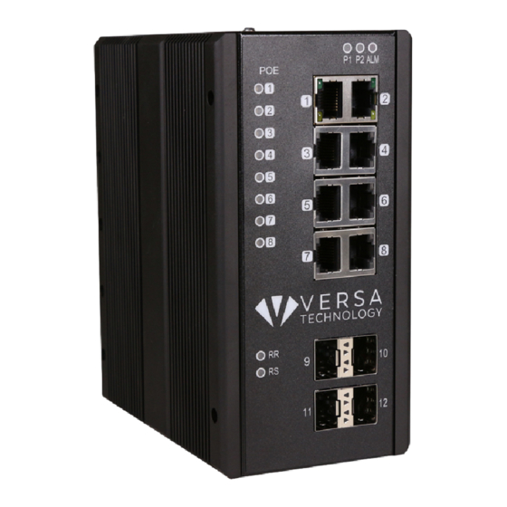
Overview VX-IGP-1204F industrial Ethernet solutions deliver high quality, wide operation temperature range, extended power input range and advanced VLAN & QoS features. It’s ideal for harsh environments and mission critical applications. Faceplate 8-Port series 10-Port series... - Page 7 8- 10 Port PL series 12 Port PL series (VX-IGP-1204F)
-
Page 8: Front Panel Introduction
Front Panel Introduction Front Panel System Status LED P1, P2 and Alarm Gigabit Ethernet Copper Ports RJ45 Gigabit Ethernet SFP ports SFP Slots POE LED POE port status RR/RS LED Device info/status Top Panel Introduction Top Panel Power Input (Dual) 6P Terminal Block Console (RS232) RJ45... -
Page 9: Technical Specifications
Technical Specifications Ethernet Operating mode Store and forward, L2 wire-speed/non-blocking switching engine MAC addresses Jumbo frames 9K Bytes Copper RJ45 Ports Speed 10/100/1000 Mbps MDI/MDIX Auto-crossover Support straight or cross wired cables Auto-negotiating 10/100/1000 Mbps speed auto-negotiation; Full and half duplex Ethernet isolation 1500 VRMS 1 minute SFP (pluggable) Ports Port types supported SFP (pluggable) Ports 100/1000Base SFP slot Support 100/1000BaseT SFP transceiver Fiber port connector LC typically for fiber (depends on module) Optimal fiber cable Typical 50 or 62.5/125 μm for multimode (mm); Typical 8 or 9/125 μm for single mode (sm) Network Redundancy Fast failover protection rings Link loss recovery < 20ms Single & Multiple rings supported Spanning Tree Protocol IEEE 802.1D STP, IEEE 802.1w RSTP, IEEE 802.1s MSTP Port Trunk with LACP Static trunk or Dynamic via LACP (Link Aggregation Control Protocol) Bridge, VLANs & Protocols Flow control IEEE 802.3x (Full Duplex) and Back-Pressure(Half Duplex) VLAN Types Port-based VLANs... - Page 10 Indicators Power Status indication Indication of power input status Ethernet port indication Link & Speed Management User Management interfaces CLI (command line interface) WEB-based Management SNMP v1, v2c Telnet (5 sessions) Management Security HTTPs, SSH Radius Client for Management Upgrade & Restore Configuration Import/Export Firmware Upgrade Diagnostic Syslog Per VLAN mirroring SFP with DDM (Digital Diagnostic Monitoring) MIBs RMON 1,2,3,9; Q-Bridge MIB, RFC 1213 MIB-II, RFC 4188 Bridge MIB DHCP Client, Server, Relay, Snooping, Option 82 NTP/SNTP Yes Environmental & Compliances Operating temperature range -40 to +75°C (cold startup at -40°C) Storage temperature range -40 to +85 °C Humidity (non-condensing) 5 to 95% RH Vibration, shock & freefall IEC68-2-6, -27, -32 Certification compliance CE/FCC; EN-50121-4 Electrical safety CSA C22, EN61010-1, CE EMC FCC Part 15, CISPR 22 (EN55022) Class A...
- Page 11 IPMC Profile IPMC Rule / Address Entry ICMP Type / Code RADIUS Server TACACS+ Server MAC-based VLAN Entry IP subnet-based VLAN Entry Protocol-based VLAN Group Voice VLAN OUI IP Interface IP Route Security Access Management MVR VLAN MAC Learning table address IGMP Group...
- Page 12 Quick Installation Equipment Mounting Cable Connecting Equipment Configuration...
-
Page 13: Quick Installation
1. Screw the DIN-Rail bracket on with the bracket and screws in the accessory kit. 2. Hook the unit over the DIN rail. 3. Push the bottom of the unit towards the DIN Rail until it snaps into place. Figure 1 VX-IGP-1204F DIN-Rail Mounting... -
Page 14: Mounting The Vx-Igp-1204F00 (Wall Mount)
Mounting the VX-IGP-1204F (Wall mount) Mounting step: 1. Screw on the wall-mounting plate on with the plate and screws in the accessory kit. Figure 2 VX-IGP-1204F Wall Mounting... -
Page 15: Ground Connections
Ground Connections VX-IGP-1204F must be properly grounded for optimum system performance. -
Page 16: Connecting The Ethernet Interface (Rj45 Ethernet)
To connect to a PC, use a straight-through or a cross-over Ethernet cable, Ÿ To connect the VX-IGP-1204F copper Port to an Ethernet device, use UTP (Unshielded Twisted Pair) or STP (Shielded Twisted Pair) Ethernet cables. The pin assignment of RJ-45 connector is shown in the following figure and table. -
Page 17: Connecting The Ethernet Interface (Fiber)
Assignment Assignment T/Rx+,T/Rx- Positive V Port T/Rx+,T/Rx- Negative V Port T/Rx+,T/Rx- T/Rx+,T/Rx- Connecting the Ethernet Interface (Fiber) Prepare a proper SFP module and install it into the optical port. Then you can connect fiber optics cabling that uses LC connectors or SC connectors (with the use of an optional SC-to-LC adapter) to the fiber optics connector. -
Page 18: Power Connection
The DC power interface is a 6-pin terminal block with polarity signs on the top panel. The VX-IGP-1204F can be powered from two power supply (input range 12V – 58V). The DC power alarm contact on the middle terminal block. -
Page 19: Console Connection
Power Connector (6P Terminal Block) Input DC 12-58V PWR1 +/- Power Input 1 +/- PWR2 +/- Power Input 2 +/- Alarm relay output Note: 1. The DC power should be connected to a well-fused power supply. Console Connection The Console port is for local management by using a terminal emulator or a computer with terminal emulation software. -
Page 20: System Reset
The RJ45 connector of the cable is connected to the Console port of VX-IGP-1204F; the DB9 connector of the cable is connected to the PC COM port. The pin assignment of the Console cable is shown below: SYSTEM RESET The Reset button is provided to reboot the system without the need to remove power. -
Page 21: Web Interface Initialization (Optional)
Web Interface Initialization (Optional) Web Browser Support IE 7 (or newer version) with the following default settings is recommended: Language script Latin based Web page font Times New Roman Plain text font Courier New Encoding Unicode (UTF-8) Text size Medium Firefox with the following default settings is recommended: Web page font Times New Roman... - Page 22 Connect & Login to VX-IGP-1204F00 Connecting to VX-IGP-1204F Ethernet port (RJ45 Ethernet port). Factory default IP: 192.0.2.1 Login with default account and password. Username: admin Password: (none)
-
Page 23: Cli Initialization & Configuration (Optional)
CLI Initialization & Configuration (Optional) Connecting to VX-IGP-1204F Ethernet port (RJ45 Ethernet port) Key-in the command under Telnet: telnet 192.0.2.1 Login with default account and password. Username: admin Password: (none) Change the IP with commands listed below: CLI Command: enable... -
Page 24: Monitoring The Ethernet Interface
Monitoring the Ethernet Interface By RJ45 Ethernet: Refer to Figure 3 for monitoring 8 Gigabit Ethernet with copper connector (RJ45). Also refer to Table 1 for the normal operational LED status. By SFP: Refer to Figure 3 for monitoring 4 Gigabit Ethernet with SFP connector. Also refer to Table 1 for the normal operational LED status. -
Page 25: Reset To Default And Save Configure
Reset to Default and Save Configure Configuration via CLI command To see what current interface and IP address is: If manager want to reset the configuration to default but keep management IP setting. (1) please execute this command: reload defaults keep-ip (2) check interface VLAN and IP address, confirm only management IP setting kept. - Page 26 Configuration via WEB UI If manager want to reset the configuration to default but keep management IP setting (1)Go to “Maintenance”à”Factory Defaults” pagination to Click “Yes” button. (2) Go to “Maintenance”à “Configuration”à”Save startup-config” pagination, then click “Save Configuration” button, then reset successfully. If manager want to reset the all configuration to default completely (1) Go to “Maintenance”à...
- Page 27 (2) Change PC’s IP address belong to 192.0.2.X networks. (3) Change WEB’s IP be 192.0.2.1(default IP) to login DUT’s Web UI. (4) Go to “Maintenance”à “Configuration”à”Save startup-config” pagination, then click “Save Configuration” button, then reset successfully.
-
Page 28: Led Status Indications
LED STATUS INDICATIONS Table 1 LED Status Indicators STATE Description On Green P1 power line has power P1 power line disconnect or does not have supply power On Green P2 power line has power P2 power line disconnect or does not have supply power On Red Alarm event occurs... - Page 29 PWR LED Indicator LED Indicator Copper Link/Act LED Copper Speed LED SFP Link LED Indicator SFP Speed LED Indicator Figure 3 LED Indicators...
- Page 30 Application Guide VLAN Application Guide Security Application Guide Ring Protection Application Guide QoS Application Guide Link Fail Alarm Application Guide 802.1x Authentication Application Guide...
-
Page 31: Vlan Application Guide
VLAN. Example 1: Default VLAN Settings Each port in the VX-IGP-1204F has a configurable default VLAN number, known as its PVID. This places all ports on the same VLAN initially, although each port PVID is configurable to any VLAN number between 1 and 4094. -
Page 32: Example 2: Port-Based Vlans
Example 2: Port-based VLANs When the VX-IGP-1204F receives an untagged VLAN packet, it will add a VLAN tag to the frame according to the PVID setting on a port. As shown in the following figure, the untagged packet is marked (tagged) as it leaves the VX-IGP-1204F through Port 2, which is configured as a tagged member of VLAN100. - Page 33 Here we set tagged VLAN100 on Port 1 and Port 2, untagged VLAN100 on Port7. Step4. Transmit untagged unicast packets from Port 1 to Port 2 and Port 7. The VX-IGP-1204F should tag it with VID 100. The packet has access to Port2 and Port 7. The outgoing packet is stripped of its tag to leave Port 7 as an untagged packet.
- Page 34 VLAN Application Guide CLI Command: vlan 1 vlan 100 interface GigabitEthernet 1/1 switchport access vlan 100 switchport trunk native vlan 100 switchport trunk allowed vlan 1,100 switchport trunk vlan tag native switchport mode trunk exit interface GigabitEthernet 1/2 switchport access vlan 100 switchport trunk native vlan 100 switchport trunk allowed vlan 1,100 switchport trunk vlan tag native switchport mode trunk exit interface GigabitEthernet 1/7 switchport access vlan 100 switchport trunk native vlan 100 switchport trunk allowed vlan 1,100 switchport mode trunk exit...
-
Page 35: Example 3: Ieee 802.1Q Tagging
VLAN Application Guide Example 3: IEEE 802.1Q Tagging VX-IGP-1204F is able to construct layer-2 broadcast domain by identifying VLAN ID specified by IEEE 802.1Q. It forwards a frame between bridge ports assigned to the same VLAN ID and can set multiple VLANs on each bridge port. - Page 36 Step2. Transmit unicast packets with VLAN tag 100 from Port 1 to Port 2 and Port 7. The VX-IGP-1204F should tag it with VID 100. The packet only has access to Port2. For Port 2, the outgoing packet leaves as a tagged packet with VID 100.
- Page 37 VLAN Application Guide vlan 100 vlan 200 interface GigabitEthernet 1/1 switchport access vlan 100 switchport trunk allowed vlan 1,100,200 switchport trunk vlan tag native switchport mode trunk exit interface GigabitEthernet 1/1 switchport access vlan 100 switchport trunk allowed vlan 1,100 switchport trunk vlan tag native switchport mode trunk exit interface GigabitEthernet 1/7 switchport access vlan 100 switchport trunk allowed vlan 1,200 switchport trunk vlan tag native switchport mode trunk exit...
-
Page 38: Security Application Guide
Application Guide Security Application Guide ACL function supports access control security for MAC address, IP address, Layer4 Port, and Type of Service. Each has five actions: Deny, Permit, Queue Mapping, CoS Marking, and Copy Frame. User can set default ACL rule to Permit or Deny. To get more clearly for these ACL function, see following table. Actions Default ACL Rule Queue... - Page 39 Application Guide ◎ One directional MAC address with one VLAN deny filtering. Step 1: Create a new ACL Profile. (Profile Name: DenySomeMac) Step 2: Create a new ACL Entry rule under this ACL profile. (Deny MAC: 11 and VLAN: 4) Step 3: Bind this ACL profile to a GE port.
- Page 40 Application Guide Step 4: Send frames between PORT-3 and PORT-4, and see test result. VX-IG VX-IG VX-IG P-1204 P-1204 P-1204 CLI Command: access-list ace 1 ingress interface GigabitEthernet 1/4 policy 1 vid 4 frametype etype smac 00-00-00-00-00-11 action deny exit interface GigabitEthernet 1/3 switchport trunk allowed vlan 4,5 switchport trunk vlan tag native...
- Page 41 Application Guide Two directional MAC address with all VLAN deny filtering. Step 1: Create a new ACL Profile. (Profile Name: DenySomeMac) Step 2: Create a new ACL Entry rule under this ACL profile. (Deny SrcMAC: 13 and DesMAC: 11) Step 3: Bind this ACL profile to a GE port. (PORT-3)
- Page 42 Application Guide Step 4: Send frames between PORT-3 and PORT-4, and see test result. VX-IG VX-IG VX-IG P-1204 P-1204 P-1204 CLI Command: access-list ace 2 ingress interface GigabitEthernet 1/3 policy 0 frametype etype smac 00-00-00-00-00-13 dmac 00-00-00-00-00-11 action deny exit interface GigabitEthernet 1/3 switchport trunk allowed vlan 4,5 switchport trunk vlan tag native interface GigabitEthernet 1/4 switchport trunk allowed vlan 4,5 switchport trunk vlan tag nativevlan 4 exit...
- Page 43 Application Guide Case 1: (b) This case acts as no ACL function. It means all frames will pass through. Case 1: (c) User can set default ACL Rule of GE port as “Permit”, then to bind a suitable profile with “Queue Mapping”...
- Page 44 Application Guide Step 4: Send frames between PORT-3 and PORT-4, and see test result. VX-IG VX-IG VX-IG P-1204 P-1204 P-1204 CLI Command: access-list ace 1 next 2 ingress interface GigabitEthernet 1/4 policy 1 vid 4 frametype etype smac 00-00-00-00-00-11 action deny exit interface GigabitEthernet 1/3 switchport trunk allowed vlan 4,5 switchport trunk vlan tag native interface GigabitEthernet 1/4 switchport trunk allowed vlan 4,5 switchport trunk vlan tag native exit...
- Page 45 Application Guide Case 1: (e) User can set default ACL Rule of GE port as “Permit”, then to bind a suitable profile with “Copy Frame” action for mirror analyzer used. It means the system will copy frames from binding GE Port to analyzer port.
- Page 46 Application Guide Step 5: Send frames between PORT-3 and PORT-4, and see test result. VX-IG VX-IG VX-IG P-1204 P-1204 P-1204 CLI Command: access-list ace 2 next 3 ingress interface GigabitEthernet 1/3 policy 0 frametype etype smac 00-00-00-00-00-13 dmac 00-00-00-00-00-11 action deny mirror redirect interface GigabitEthernet 1/5 exit interface GigabitEthernet 1/3 switchport trunk allowed vlan 4,5 switchport trunk vlan tag native interface GigabitEthernet 1/4 switchport trunk allowed vlan 4,5 switchport trunk vlan tag native exit...
- Page 47 Application Guide Case 1: (f) This case means all frames will not pass through. Case 1: (g) User can set default ACL Rule of GE port as “Deny”, then to bind a suitable profile with “Permit” action for ACL. It means GE port can not pass through all packets but ACL entry of the profile binding. One directional MAC address with one VLAN permit filtering.
- Page 48 Application Guide Step 4: Send frames between PORT-3 and PORT-4, and see test result. VX-IG VX-IG VX-IG P-1204 P-1204 P-1204 CLI Command: access-list ace 4 ingress interface GigabitEthernet 1/4 policy 3 tag tagged vid 4 frametype etype smac 00-00-00-00-00-11 exit interface GigabitEthernet 1/3 switchport trunk allowed vlan 4,5 switchport trunk vlan tag native interface GigabitEthernet 1/4 switchport trunk allowed vlan 4,5 switchport trunk vlan tag native exit...
- Page 49 Application Guide Two directional MAC address with all VLAN permit filtering. Step 1: Create a new ACL Profile. (Profile Name: AllowSomeMac) Step 2: Create a new ACL Entry rule under this ACL profile. (Allow SrcMAC: 13 and DesMAC: 11) Step 3: Bind this ACL profile to a GE port. (PORT-3)
- Page 50 Application Guide Step 4: Send frames between PORT-3 and PORT-4, see test result. VX-IG VX-IG VX-IG P-1204 P-1204 P-1204 CLI Command: access-list ace 5 ingress interface GigabitEthernet 1/3 policy 5 frametype etype smac 00-00-00-00-00-13 dmac 00-00-00-00-00-11 exit interface GigabitEthernet 1/3 switchport trunk allowed vlan 4,5 switchport trunk vlan tag native interface GigabitEthernet 1/4 switchport trunk allowed vlan 4,5 switchport trunk vlan tag native exit...
- Page 51 Application Guide Case 1: (h) Because the default ACL Rule of GE port is “Deny”, Queue Mapping action has no sense. We do not do this case. Case 1: (i) Because the default ACL Rule of GE port is “Deny”, CoS Marking action has no sense. We do not do this case.
- Page 52 Application Guide Step 5: Send frames between PORT-3 and PORT-4, see test result. VX-IG VX-IG VX-IG P-120 P-120 P-120...
- Page 53 Application Guide CLI Command: access-list ace 5 next 6 ingress interface GigabitEthernet 1/3 policy 5 frametype etype smac 00-00-00-00-00-13 dmac 00-00-00-00-00-11 Exit monitor destination interface GigabitEthernet 1/5 monitor source cpu both exit interface GigabitEthernet 1/3 switchport trunk allowed vlan 4,5 switchport trunk vlan tag native interface GigabitEthernet 1/4 switchport trunk allowed vlan 4,5 switchport trunk vlan tag native exit...
-
Page 54: Case 2: Acl For Ip Address
Application Guide Case 2: ACL for IP address For IP address ACL, it can filter on source IP address, destination IP address, or both. It also supports to set IP range ACL. When it filters on both IP address, packets coincident with both rules will take effect. In other words, it does not do filter if it only coincident with one rule. -
Page 55: Ring Version 2 Application Guide
To have a reliable network is very important to Ethernet applications, especially in Industrial domain. Versa Technology’s VX-IGP-1204F provides a mini-second grade failover ring protection; this feature offers a seamless working network even if encountering some matters with connections. It is able to be... -
Page 56: Ring Version 2 Feature
Application Guide Ring Version 2 Feature Group 1 - It support option of ring-master ring-slave # Ring - it could be master or slave. # When role is ring master, one ring port is forward port and another is block port. The block port is redundant port. - Page 57 Application Guide # Dual-Homing # When role is dual-homing, one ring port is primary port and another is backup port. This backup port is redundant port. In normal state, it is blocked. Group 3 - It support configuration of the chain and balancing-chain.
- Page 58 Application Guide # Balancing Chain - it could be central-block, terminal-1/2 or member. # When role is balancing-chain/central-block, one ring port is member port and another is block port. The block port is redundant port. It is blocked in normal state. # When role is balancing-chain/terminal-1/2, one ring port is terminal port and another is member port.
-
Page 59: How To Configure Ringv2
Application Guide How to Configure Ringv2 Configuration (Console) To configure the ring protection in VX-IGP-1204F series management switch, 1. Login “admin” account in console configure terminal 2. Go to Configure mode by ” ” ringv2 protect group1 Go to configure ring protection group by command “... - Page 60 Application Guide Configuration (Web UI) This document is introduction of the Industrial Ethernet Switch Software Spec for Ringv3. In current design, one device supports 3 ring index, including Ring & Chain (single ring, dual ring, coupling, dual-homing, chain, and balancing-chain.) Note 1 - It must enable group1 before configure group2 as coupling.
- Page 61 Application Guide Ring Master à “ RingV2” Web page 1. Go to “Configuration Enable Index1, and Select Role as Ring(Master) Select one port as a “Forward Port”, another is “Block Port” Ring Slave à “ Go to “Configuration RingV2” Web page Enable Index1, and Select Role as Ring(Slave) 3.
- Page 62 Application Guide 4. Enable Index2, and Select Role as “Coupling(Primary)” 5. Select one port as a “Primary Port”. Coupling Backup à “ 1. Go to “Configuration RingV2” Web page 2. Enable Index1, and Select Role as Ring(Slave) 3. Select two ports as a “Forward Port”. 4.
- Page 63 Application Guide Chain Configuration Chain - Member à “ 1. Go to “Configuration RingV2” Web page 2. Disable Index1 and Index2, then enable Index3 3. Select Role to “Chain(Member)” 4. Select two member ports for this chain member switch. Chain - Head à...
- Page 64 Application Guide Chain - Tail à “ 1. Go to “Configuration RingV2” Web page 2. Disable Index1 and Index2, then enable Index3 3. Select Role to “Chain(Tail)” 4. Select a member port and a tail port for this chain tail switch. Balance Chain Configuration Balance Chain –...
- Page 65 Application Guide 4. Select a member port and a block port for this central block switch. Balance Chain –Terminal-1 and -2 à “ 1. Go to “Configuration RingV2” Web page 2. Disable Index1 and Index2, then enable Index3 3. Select Role to “Balancing Chain(Terminal-1 or -2)” 4.
-
Page 66: Qos Application Guide
The traffic descriptor defines the shape parameter on every VLAN priority for Ethernet interface. Currently KGS supports Strict Priority and SP+WRR(Weighted Round Robin) scheduling methods on each port. Please find the detail reference on VX-IGP-1204F user manual. -
Page 67: Example 1: Spq Without Shaping (Default Profile)
Stream0 includes VLAN Priority0, Stream1 includes VLAN Priority7. Set PORT-2 link speed to 100Mbps. Expected Result: We expect PORT-2 only can receive 100Mbps of Stream1, and Stream0 will be discarded. This case will help user to know how SPQ works on the VX-IGP-1204F. Gigabit port VLAN Priority & Queue mapping: l Stream0 :... - Page 68 Application Guide Web management: Step1. Go to Configuration -> Ports -> set port 2 link speed to 100Mbps full duplex. Step2. Select Configuration -> VLANs ->Create a VLAN with VLAN ID 100. Enter a VLAN name in the Name field. Here we set tagged VLAN100 on PORT-1 and PORT-2.
- Page 69 Application Guide CLI configuration command: interface GigabitEthernet 1/1 switchport trunk native vlan 100 switchport trunk allowed vlan 1,100 switchport trunk vlan tag native switchport mode trunk interface GigabitEthernet 1/2 switchport trunk native vlan 100 switchport trunk allowed vlan 1,100 switchport trunk vlan tag native switchport mode trunk...
-
Page 70: Example 2: Spq With Shaping
Expected Result: We expect PORT-2 only can receive 20Mbps of Stream1, and 80Mbps of Stream0. This case will help user to know how SPQ works on the VX-IGP-1204F. VDSL port VLAN Priority & Queue mapping: l Stream0 :... - Page 71 Application Guide l Stream3 : (for Learning) Dst Mac : 00:00:00:00:10:01 Src Mac : 00:00:00:00:20:01 Vlan : 100 Vlan prio : 0 Send rate : 10Mbps Packet length: 1518bytes l Stream4 : (for Learning) Dst Mac : 00:00:00:00:10:02 Src Mac : 00:00:00:00:20:02 Vlan : 100 Vlan prio : 0 Send rate : 10Mbps...
- Page 72 Application Guide Step2. Select schedule mode be “”Strict Priority” and set shaping rate for queue 0 and queue 7 as below. CLI configuration command: interface GigabitEthernet 1/2 switchport trunk native vlan 100 switchport trunk allowed vlan 1,100 switchport trunk vlan tag native switchport mode trunk qos queue-shaper queue 0 80000 qos queue-shaper queue 7 20000...
-
Page 73: Igmp Application Guide
IGMP Application Guide IGMP is an acronym for Internet Group ManagementProtocol. It is a communications protocol used to manage the membership of Internet Protocol multicast groups. IGMP is used by IP hosts and adjacent multicast routers to establish multicast group memberships. - Page 75 Example2: 1. Go to “ConfigurationàIPMCàBasic Configuration” to select the check box of “Snooping Enable” 2. Un-select the check box of ”Unregistered IPMCv4 Flooding Enabled” 3. If Multicast stream is from L3 switch, then the uplink port have to be “Router Port” Notice: If an aggregation member port is selected as a router port, the whole aggregation will act as a router port.
- Page 76 (4) Go to “ConfigurationàIPMCàVLAN Configuration” to select the check box of “Snooping Enable” and set VLAN ID of port14.
- Page 78 Example3: In this scenario, these clients belong to multiple vlans, you have to create more one vlan to be the agent for all client vlans. To create a vlan : go to ”ConfigurationàVLANsàAllow Access VLANs”, then set port 14 be vlan200 member port.
- Page 79 Go to “ConfigurationàIPMCàVLAN Configuration” to select the check box of “Snooping Enable” and set VLAN ID of port14. If there is no querier on the L3 switch, you have to select “Querier Election”, and set the “Querier Address ”, the IP address is in the same network as uplink interface. Selecet the IGMP version as server.
- Page 80 How to Configuration VLC VLC Configure on IGMP Server (1) In «Media » area of top tool bar to select “Stream” (2) Select a video or voiced file to play...
- Page 81 (3) Confirm the file is right, then click “Next” twice.
- Page 82 (4) Select stream type as “UDP” and click “Add” button. (5) Set stream IP, the range is 224.0.0.1 to 239.255.255.254, and protocol port is 1234. Here I set stream IP is 255.0.0.1...
- Page 83 (6) Select ”Sort out all stream” and click “Stream” button, then the stream start to send to switch. VLC Configure on IGMP Client (1) In «Media » area of top tool bar to select open network stream...
- Page 84 (2) Set the stream IP and protocol port as previous setting on server, the protocol type is “UDP”, the format should as below circle, then click “PLAY” button. Back to management switch, Go to “Monitorà IPMCà Groups Information”, you will see the stream IP in the table.
-
Page 85: 802.1X Authentication Application Guide
(port1~port10). You should enable 802.1x function of the system, and choose ports and type you want to apply. If VX-IGP-1204F enable 802.1x authentication control for certain Ethernet port, this port should be authenticated before using any service from the network. Please see the following description. - Page 86 Step 2: Edit secret key for Radius server. Setting: client 20.20.20.0/24 { The secret in the secret = a1b2c3d4 VX-IGP-1204F should be the same with this one.
-
Page 87: Example
Here we take an example of 802.1x Authentication via VX-IGP-1204F to be authenticated by RADIUS server. In a basic example, we take port 1 as a testing port which enables 802.1x in VX-IGP-1204F. With default configuration, use the following Web UI setting . - Page 88 Step1. Go to Configuration -> Security -> AAA -> Radius. Click “Add New Server”, Input “20.20.20.20” for server, and “ a1b2c3d4 ” for secret key. Then click “Save” button.
- Page 89 Step 2: Select the IEEE802.1x Authentication Enable check box, then to configure EAP type to MD5-Challenge. After setting this function in NIC, supplicant should enter a correct pair of account and password in order to use this Ethernet port service from VX-IGP-1204F.
- Page 90 Authentication Behavior Supplicant should pass authentication process in order to use any service. After supplicant enters correct account and password which stored in RADIUS server, it can be authenticated successfully. The authentication process is as following. VX-IGP-120...
-
Page 91: Power Over Ethernet (Poe) Application Guide
Power over Ethernet (PoE) Application Guide IVS-PL5xx series switches support PoE function for connected powered device. The operation mode contains 802.3af (15.4W), 802.3at (30W), and 802.3at with 4 pair used (60W). 60 watt only can be applied for port 1 and 2. Each port has 5 classes for selection, class 0~4. And, total power budget of the system is up to 240 watt. -
Page 92: Power Management Mode
Power Management Mode There are 2 modes for configuring when to shut down the ports: 1. Actual Consumption: In this mode the ports are shut down when the actual power consumption for all ports exceeds the amount of power that the power supply can deliver or if the actual power consumption for a given port exceeds the reserved power for that port. - Page 93 1. PoE Power Supply For being able to determine the amount of power the PD may use, it must be defined what amount of power a power source can deliver. Valid values are in the range 0 to 240 Watts. 2.
- Page 94 PoE Power Scheduling & Reset The power scheduling is used to control the power alive interval on PoE port. It is allowed to set the specific interval to schedule power on/off in one week. The current scheduling state is displayed graphically during the week. Green indicates the power is on and red that it is off.
- Page 95 Example 1 Parameter Setting: Reserved Power determined: Class Power Management Mode: Actual Consumption Primary Power Supply: Test Port Port 1: 802.3at with critical priority Port 2: 802.3af with high priority Port 3: 802.3af with low priority PD Power Consumption Port 1: 1.3 watt (PoE Splitter) Port 2: 1.3 watt (PoE VoIP Phone) Port 3: 3.8 watt (PoE WiFi AP) Web Configuration...
- Page 96 Example 2 Parameter Setting: Reserved Power determined: Allocation Power Management Mode: Reserved Power Primary Power Supply: 138 W (> all port reserved power) Port Maximum Power Port 1: 30 W Port 2~ Port8: 15.4 W Total: 137.8 W PD Power Consumption Port 1: 1.3 watt (PoE Splitter) Port 2: 1.3 watt (PoE VoIP Phone) Port 3: 3.8 watt (PoE WiFi AP) 4.
Need help?
Do you have a question about the VX-IGP-1204F and is the answer not in the manual?
Questions and answers