Table of Contents
Advertisement
Quick Links
Advertisement
Table of Contents

Related Manuals for Versa Technology VX-GPH8245


Summary of Contents for Versa Technology VX-GPH8245
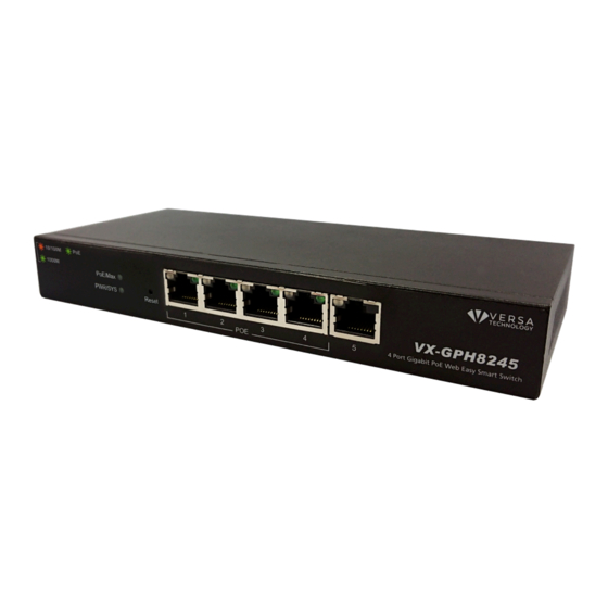
- Page 1 VX-GPH8245 5 port Gigabit Ethernet Smart-lite Switch w/ 4 PoE+ ports User Manual...
- Page 2 Default-IP 192.168.2.1 Username & Password: admin...
-
Page 3: Table Of Contents
Table of Contents Chapter 1 Introduction to the Web Smart PoE Switch ······································ 4 1.1 General Description ················································································ 4 1.2 The Front Panel ····················································································· 4 1.3 LEDs Definition ······················································································ 4 1.4 The Rear Panel ······················································································ 5 1.5 Installation ···························································································· 6 Chapter 2 Basic Web Management Information ·············································... -
Page 4: Introduction To The Web Smart Poe Switch
Chapter 1 Introduction to the Web Smart PoE Switch 1.1 General Description 1.2 The Front Panel The following figure shows the front panel of the switch. The following table describes the port labels on the front panel. LABEL DESCRIPTON 5 10/100/1000 RJ-45 Ethernet Connect these ports to a computer, a hub, an Ethernet switch or router Ports... -
Page 5: The Rear Panel
The Reset Button Reset the switch to its factory default configuration via the RESET button. Press the RESET button for ten seconds and release. The switch automatically reboots and reloads its factory configuration file. The RESET button is on the front panel of the switch. 1.4 The Rear Panel The following figure shows the rear panel of the switch: Power Receptacle... -
Page 6: Installation
1.5 Installation This switch can be placed on your desktop directly, or mounted on the wall. Please refer to the instructions for installation. Before installing the switch, we recommend: 1. The switch is placed with appropriate ventilation environment. A minimum 25 mm space around the unit is recommended. - Page 7 2. Category 3, 4, 5 or 5e, 6 UTP/STP cable: To make a valid connection and obtain the optimal performance, an appropriate cable that corresponds to different transmitting/receiving speed is required. To choose a suitable cable, please refer to the following table. Media Speed Wiring...
-
Page 8: Chapter 2 Basic Web Management Information
Chapter 2 Basic Web Management Information 2.1 System login 1. Start your web browser. 2. Type “http://”and the IP address of the switch (for example, the default management IP address is 192.168.2.1) in the Location or Address field. Press [ENTER]. 3. - Page 9 – Click the menu items to open the screen in the main window. – Displays system information such as MAC address and firmware version and so on.
-
Page 10: Web Management Configuration
Chapter 3 Web Management Configuration 3.1 System System page allow user to configure and browse some system information such as Model Name, Device Name, Firmware Version, MAC address, IP address, Loop status and PoE status. User could configure Device Name and IP address in System page. LABEL DESCRIPTION Device name of the switch. -
Page 11: Management
3.2 Management In Management page, you can change the HTTP port. “Reset” / “Reboot” button can restore default and reboot system. System also can backup and restore configuration file via “Restore” / “Backup” button. Firmware can be upgraded via “Upgrade” button. 3.2.1 Firmware Upgrade User has to enter Loader Mode to upgrade firmware. - Page 12 Select the firmware upgrade file. Its name will appear in the Upgrade File field. And then click the “Upgrade” button to commence the firmware upgrade. Click OK to upgrade firmware. Wait for 30 seconds. When the upgrading process is done, it will redirect to Login page.
-
Page 13: Port Status
3.3 Port Status In Port page, you can see the Link Status and TX/RX counts of all ports. You also can click “Clear Counters” to reset the TX/RX counts. -
Page 14: Vlan
3.4 VLAN A virtual local area network, virtual LAN or VLAN, is a group of hosts with a common set of requirements that communicate as if they were attached to the same broadcast domain, regardless of their physical location. A VLAN has the same attributes as a physical local area network (LAN), but it allows for end stations to be grouped together even if they are not located on the same network switch. -
Page 15: Port-Based Vlan
3.4.2 Port-Based VLAN Click Add VLAN, and it will show as below. Select the VLAN member port. -
Page 16: Trunking
3.5 Trunking Link Aggregation Control Protocol (LACP) that allows you to bundle several physical ports together to form a single logical channel. LACP allows a switch to negotiate an automatic bundle by sending LACP packets to the peer. Select Enable to enable LACP function and connect Port 1 and Port 2 to another switch that supports LACP function. -
Page 17: Mirror
3.6 Mirror The Mirror function copies all the packets that are transmitted by the source port to the destination port. It allows administrators to analyze and monitor the traffic of the monitored ports. LABEL DESCRIPTION Enable Mirror Check to enable Mirror function. Mirror Direction Select mirror direction: Ingress, Egress or Both Monitor Port... -
Page 18: Qos
3.7 QoS Quality of Service (QoS) features are used to prioritize the use of bandwidth in a switch. When QoS features are enabled, traffic is classified as it arrives at the switch, and processed through on the basis of configured priorities. 3.7.1 Port-Based QoS LABEL DESCRIPTION... -
Page 19: Ieee 802.1P Qos
3.7.2 IEEE 802.1p QoS LABEL DESCRIPTION Select WFQ(Weighted Fair Queuing) or Strict Priority Scheduler Method Queue ID to configure Priority If the queue type is WFQ, set the queue weight for the queue. Weight Click Apply to save your changes to the switch. Apply... -
Page 20: Broadcast Storm Control
3.8 Broadcast Storm Control Broadcast storm control limits the number of broadcast frames that can be stored in the switch buffer or sent our from the switch. Broadcast frames that arrive when the buffer is full are discarded. Select the limitation to reduce broadcast traffic coming into you network. The types of storm control include Broadcast, Multicast and DLF (Destination Lookup Failure). -
Page 21: Loop Detect / Prevent
3.9 Loop Detect / Prevent In “Loop Detect/Prevent” page, system will detect/prevent loop automatically based on your selection. Loop Detection: the LINK/ACT LED will blink in a regular time (about 1s). Loop Prevention: One Ethernet port will be disabled and then up again. -
Page 22: Igmp Snooping
3.10 IGMP Snooping IGMP snooping is the process of listening to Internet Group Management Protocol (IGMP) network traffic. The feature allows a network switch to listen in on the IGMP conversation between hosts and switch. By listening to these conversations the switch maintains a map of which links need which IP multicast streams. -
Page 23: Poe
3.11 PoE In “PoE” page, PoE power budget, port status, etc. are shown below. Click port number above, you can turn on/off PoE port on PoE port configuration page as below. -
Page 24: Password
3.12 Password In “Password” page, you can change user name and password for security. -
Page 25: Logout
3.13 Logout Click “Logout” to logout the switch. After logout, Web UI will be redirect to login page immediately. -
Page 26: Product Specifications
Product Specifications IEEE802.3, IEEE802.3u, and IEEE802.3ab IEEE 802.3x flow control IEEE 802.1p class of service, priority protocols IEEE 802.1Q VLAN tagging Standard IEEE 802.3ad LACP aggregation IEEE 802.3az Energy Efficient Ethernet (EEE) IEEE 802.3af PoE IEEE 802.3at PoE+ 5* 10/100/1000Mbps ports Interface 4* PoE ports (Supports IEEE 802.3af and IEEE 802.3at) Transmission...
Need help?
Do you have a question about the VX-GPH8245 and is the answer not in the manual?
Questions and answers