
Related Manuals for Versa Technology VX-GPF1626


Summary of Contents for Versa Technology VX-GPF1626
- Page 1 VX-GPF1626 Quick Installation Guide 2016, Versa Technology Corporation. All rights reserved. All brand and product names are trademarks or registered trademarks of their respective companies...
-
Page 2: Table Of Contents
Contents Chapter 1 Introduction ................ 1 Overview ............................1 Front panel of the Switch ......................1 Rear panel of the Switch ......................2 Chapter 2 Installing The Switch ............3 Package Contents ........................4 Mounting the Switch in a 19-inch Rack ................4 Mounting the Switch on Desk or Shelf ................5 Connecting the AC Power Cord .....................6 Installing SFP Modules ......................7 Connecting Console Port ......................7... -
Page 3: Chapter 1 Introduction
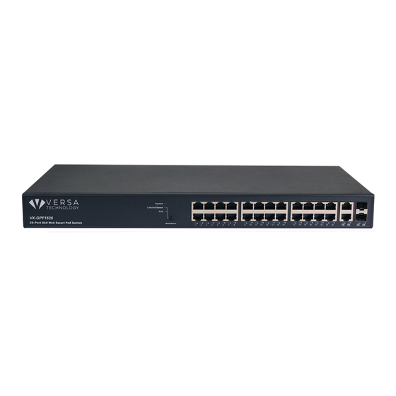
Chapter 1 Introduction Overview The VX-GPF1626 is an IEEE-compliant, 26-port PoE GbE Web Smart+ Switch with powerful management features that will boost your network’s performance. This guide describes hardware installation and basic troubleshooting for the unit. Front panel of the Switch... -
Page 4: Rear Panel Of The Switch
Table 2 System Status LED SYSTEM LED Condition status Green Lit when power is coming up System Table 3 Mode Status LED Condition Status Green when the link is 1000Mbps Green Yellow when the link is 100Mbps Link/ACT/Speed Yellow Off when the link is 10Mbps Green Lit Green when LEDs of each port are in PoE Mode Rear panel of the Switch... -
Page 5: Installing The Switch
Chapter 2 Installing The Switch Circuit devices are sensitive to static electricity, which can AUTION damage their sensitive electronics. Dry weather conditions or walking across a carpeted floor may cause users to acquire a static electrical charge. To protect your device, always: Touch the metal chassis of your computer to ground the static electrical ... -
Page 6: Package Contents
Package Contents VX-GPF1626 GbE Management Switch Four adhesive rubber feet Mounting Accessory (Optional for 19”Rack Shelf) Installation Guide AC Power cord Console cable Mounting the Switch in a 19-inch Rack Step1. Attach the mounting brackets to both sides of the chassis with screws. -
Page 7: Mounting The Switch On Desk Or Shelf
Mounting the Switch on Desk or Shelf Step1. Verify that the workbench is sturdy and reliably grounded. Step2. The rubber feet are included in the accessory kit. Attach the four adhesive rubber feet to the bottom of the switch. Figure 6 Attaching the Rubber Feet... -
Page 8: Connecting The Ac Power Cord
Connecting the AC Power Cord Figure 7 Connecting the AC power cord to the AC power receptacle Step1. Connect one end of the AC power cord to the AC power receptacle on the switch. Step2. Connect the other end of the AC power cord to the AC power outlet. Step3. -
Page 9: Installing Sfp Modules
Installing SFP Modules You can install or remove a mini-GBIC SFP from a mini-GBIC slot without having to power off the switch. Use only Manufacture mini-GBIC. Step1. Insert the module into the switch port. Step2. Press firmly to ensure that the module fits into the connector. Figure 8 Installing a SFP Module into a SFP Module Slot Connecting Console Port Figure 9 Connecting Console Port... -
Page 10: Managing Switch Using The Web Interface
Chapter 3 Managing Switch Using the Web Interface Manage the Switch Using Web Browser After you power up the switch for the first time, you can configure the switch using a web browser. For more information about managing the switch, see the user interface manual. Figure 10 Web Interface login page Step1. -
Page 11: Chapter 4 Troubleshooting
Chapter 4 Troubleshooting Troubleshooting Chart The following table lists Issues, Causes, and Action to possible problems. Table 3 Troubleshooting Chart Issues Cause Action SYSTEM LED Off No power is received. Check the power cord connections for the switch and the connected device. Make sure that all cables used are correct and comply with Ethernet specifications. -
Page 12: Appendix A Technical Specifications
Appendix A Technical Specifications Hardware Specification Table 4 Hardware Specification Port Configuration 10M/100M/1G RJ45 Port 100M/1G/2.5G RJ45 Port 100M/1G/10G RJ45 Port 100M/1G SFP Port 1G/2.5G SFP Port 1G/10G SFP+ Port GbE RJ45/SFP Combo Port Console Port Total Ports PoE Function IEEE802.3at (PoE+ 30W) IEEE802.3af (PoE 15.4W) UPoE(60W) -
Page 13: 1000 Mbps Gigabit Ethernet Collision Domain
1000 MBPS Gigabit Ethernet Collision Domain Table 5 Maximum 1000BASE-T Gigabit Ethernet Cable Length Cable Type Maximum Cable Length Connector Category 5, 5e or 6 100-ohm UTP 100.m (328 ft) RJ-45 or STP Table 6 Maximum 1000BASE-SX Gigabit Fiber Cable Length Fiber Size Fiber Bandwidth Maximum Cable Length...
Need help?
Do you have a question about the VX-GPF1626 and is the answer not in the manual?
Questions and answers