Table of Contents
Advertisement
Quick Links
Advertisement
Table of Contents

Related Manuals for Sim2 NERO 4S UHD


Summary of Contents for Sim2 NERO 4S UHD
- Page 1 SIM2 BV International Srl NERO User Guide NERO4...
- Page 2 NERO User Guide...
- Page 3 Contents Important Information About this User Guide & Safety Environment Notice Introduction System Components Overview Remote Control Product Overview Connections Connecting source to the projector Keypad Installation Location Mounting Connections Switching On and Off Temperature LED indicator Operation Main Menu Display –...
- Page 4 NERO User Guide...
- Page 5 Inside the housing there are electrical parts carrying dangerously high voltages and parts operating at high temperature. Never open the housing. Entrust all servicing and repair work to a SIM2 Authorized Service Center. Opening the housing voids the war- ranty.
- Page 6 the electrical outlet. Use only the specified power supply. Connect the projector to the electrical supply with rated voltage of between 100-240 V AC, 50/60 Hz and equipped with a protective earth connection. If you are not sure of your domestic electrical out - let, contact an electrician.
- Page 7 NERO handling and transportation Do not pickup the projector by its lens. Do not insert objects through the openings in the projector Make sure that no objects are inserted inside the projector. If this should occur, dis- connect the projector from the power supply immediately and call an authorized tech- nician.
- Page 8 You may return your old equipment to your SIM2 Authorized Dealer free of charge when you buy a new product that is equivalent or has the same func- tions as the old one. Contact SIM2 to find your local dealer.
- Page 9 In order to obtain the best projected image accuracy, a delicate balance is required between the light engine, the DLP® chipset and the video processing electronics. Building on its heritage of high-end light engine design, SIM2 has invested heavily in the development of a high precision telecentric optical system. The pure- glass lens provides an unprecedented resolution to guarantee exceptional on-screen clarity.
-
Page 10: System Components
Allen Screw (of 2.5mm or 0.0984 inch) for manual adjustments of optical shift H,V If any items are missing or damaged, contact your SIM2 Authorized Dealer as soon as possible. Keep the original packaging in case anything has to be shipped. -
Page 11: Remote Control
3 Overview Remote Control Power Off Power On Brightness Gamma Contrast Lens Color Settings Iris Aspect Pure Engine Display Mode 14,16,17, Arrows for Menu 18,20 Menu Info Light Re-Sync HDMI 1 HDMI 2 HDMI 3 VGA/YPbPr NERO User Guide... - Page 12 Power Off Turn Off the projector Power On Turn On the projector Brightness Adjust the brightness of the image Gamma Set up gamma curve type Contrast Control the degree of difference between the lightest and darkest parts of the picture Lens Configure the lens settings Color Settings...
- Page 13 If you are using a programmable remote control, the setup software probably al- lows importing Hex codes. See “SIM2 NERO IR Control” document, for a list of all the projector codes.
- Page 14 Replace the batteries with new ones when the operating range of the remote control decreases. Replace only with the same or equivalent type recommended by the man- ufacturer. Dispose of used batteries according to local regulations. Make sure you do not mix old and new batteries or different types of batteries.
-
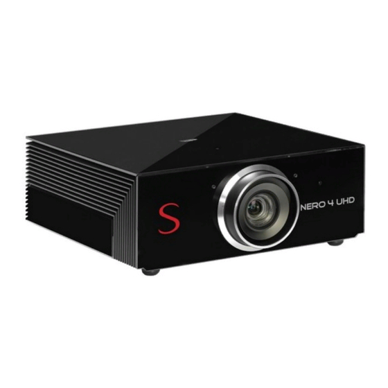
Page 15: Product Overview
Product overview IR Receiver Ventilation Outlet LED Status Indicators Power Socket Tilt-Adjustment Feet Keypad Lens Input / Output Optical Lens Shift Glass safety screw Ventilation Inlet NERO User Guide... - Page 16 Connections Inputs D HDMI 1 v1.4a, HDCP 1.4 FHD HDMI 2 v2.0, HDCP 2.2 UHD DisplayPort v1.2 G VGA/YPbPr VESA HD15. Support YpbPr. H RJ45 Ehternet interface for commands and control. Support web control. HDMI 3 v1.4a, HDCP 1.4 FHD K Wired RC Wired IR receiver Control/...
-
Page 17: Connecting Sources To The Projector
Connecting sources to the projector DisplayPort Cable 12 V DC Jack VGA Cable HDMI Cable Inputs RCA (YpbPr) Component Cable HDMI Cable Output RJ-45 Cable Wired Remote Control Cable RS232 Cable NERO User Guide... - Page 18 Keypad Power For Directional Select Keys Re-Sync Information Source Focus Zoom Not Used Menu NERO User Guide...
-
Page 19: Installation
4 Installation This section provides instructions for the installation of the NEOR4 projector. Important: Installation procedures should be performed by a qualified AV system spe- cialist. Location When installing the NERO projector, take the following considerations into account. Installation Type Select the installation type that best suits your needs: ... - Page 20 Nevertheless, even if the best materials and adhesives available in the market, in or- der to guarantee a safe application on the long long run, exclusively for the ceiling mounting applications, SIM2 has equipped the projector with glass safety screw that are aesthetic part of its cabinet (see K at page 12).
- Page 21 Ceiling Mounting Invert the projector and suspend it from the ceiling using a specific brkt4 bracket, de- scribed in the chapter 10, at page 52. Orientation By default, the NERO is configured for a Front installation (projector installed up- right and in front of the screen). If the projector is installed behind the screen or in- verted, you can use the image orientation function of the projector .
- Page 22 Mechanical Lens Shift The NERO provides manual Horizontal and Vertical Shift controls. Horizontal: +/-30% offset (with tolerance +/- 5%), when Vertical has 0% offset Vertical: +75% ~ -75% offset (with tolerance +/- 5%), when Horizontal has 0% offset. Use the Allen Screw (of 2.5mm or 0.0984 inch) available in the standard accessories in the package.
- Page 23 Connections Proceed as follows to connect the NERO to video sources, control devices, screen control systems and AC power. When connecting your equipment: turn off all equipments before making any connections use the correct signal cables for each source ...
- Page 24 Control You can connect the NERO projector to a Personal Computer or a control system through one of the following methods: RS-232 port, using a standard 9-pin straight serial cable RS-232 port, using a USB to serial converter cable. In this case, installation of a device driver provided by the cable manufacturer may be required.
-
Page 25: Switching On And Off
Switching On and Off Switching On Securely connect the power cord supplied and the signal cable. When con- nected, the Power LED will turn red. II. Turn on the projector by pressing button either on the back panel of the pro- jector or the “... -
Page 26: Temperature Led Indicator
Temperature LED indicator Power LED is bi-color (Blue and Red) When the warning indicators come on, the projector will automatically shutdown: 1.“ ” LED indicators flashes red. 2.“ ” LED indicator is lit red and if “ ” LED indicator flashes red. This indicates the projector has overheated. -
Page 27: Operation
5 Operation Main Menu The main menu gives access to all projector adjustments. It is divided in four main sec - tions: Display Setup Network Information with various item and submenus in each of them. To enter the main menu and select the desired section press on the remote control. - Page 28 This PC-based software gives calibration experts unprecedented control over the projector image quality. SIM2 recommends the use of LCC software to calibration experts only, by using spec- trophotometers or color probes to correctly analyze and adjust the colorimetry.
-
Page 29: Display - Image Settings
Display This menu section provides access to common image quality adjustments. Display – Image Settings Page 1 Page 2 NERO User Guide... - Page 30 Note: Any NERO is factory adjusted to reach the HDTV REC709 standard in SIM2 premises: selecting Display Mode “Natural”, Color Gamut “HDTV” and Color Tempera- ture “D65”. These setup reproduce, as close as possible, the image the way the movie director intended;...
- Page 31 Dynamic Range This adjustment lets you choose the standard SMPTE 2084 curve, that better match the characteristic of your installation. AUTO: this mode selects one EOTF SMPTE 2084 curve preset, between HDR1, HDR2, HDR3 and HDR4, depending of signal content. SDR: this mode is suitable for showing images without HDR contents.
- Page 32 well-lit white objects surrounded by light objects with lower level lighting, and try to ensure that all the objects can be separately identified. Press ◂ to decrease the contrast Press ▸ to increase the contrast Range [-50 .. 50] Color Adjust a video image from black and white to fully saturated color.
- Page 33 This allow you to set up gamma curve type. After the initial setup and fine tuning is completed, utilize the Gamma adjustment steps to optimize you image output. The available settings are: Film: for home theater Video (2.6): for video or TV source ...
- Page 34 HDTV: the color gamut defined by the standards. LCC: the color gamut defined by the user through the LCC software. The default starting value is the HDTV REC709 standard. When selected the LCC color gamut, the CMS menu and the Color Temperature are dimmed. With Live Color Calibration (LCC) you can change any of the color gamut directly entering absolute values.
- Page 35 Live Color Calibration – PC sw application SIM2 has developed with the experience gained over many years of projection as a premium brand, a PC SW that facilitates the tricolor calibration of its high-end machines: the Live Color Calibration, now arrived at Generation 2 and Release 4.x.
- Page 36 Signal ↵ Press the to enter the menu and then use ▴ or ▾ to select item. This function is available only for analog input signal (RGB or Component) and permit to adjust the signal options. Automatic Configure automatically the signal (the frequency and phase items are grayed out).
- Page 37 Brightness Mode Press the ↵ to enter the menu. This item activate or not an automatic dimmer lamp function. Press ◂ or ▸ to select its status. Range [Bright, Eco] Eco: dim the projector lamp which will lower power consumption and extend the lamp life.
-
Page 38: Display - Aspect Ratio
Display – Aspect Ratio Press the ↵ to enter the menu. Press ◂ or ▸ to select the status. Range [4:3, 16:9, LBX, Superwide, Native, Auto] This adjustment changes the dimensions and aspect ratio (relationship between width and height) of the displayed image. There are six default aspects available. You can se - lect a different aspect for each source: the selected aspect ratio will be automatically applied the next time the relative source is displayed. - Page 39 Scaling Table 16:9 Screen 480i/p 576i/p 720p 1080i/p 2160p Scale to 2880 x 2160 16:9 Scale to 3840 x 2160 3840 x 1620 center, then scale to 3840 x 2160 for display No resize image, 1:1 mapping and centered. This format shows original image Native without scaling.
-
Page 40: Display - Digital Zoom
Display – Edge Mask Edge mask the image to remove video encoding noise on the edge of video source. It removes the outer edges of the image and magnifies the remaining portion of the image to fill the display area. It is useful with sources that output images with imper- fections around their borders. - Page 41 Setup This menu section provides access to installation adjustments. Page 1 Page 2 Projection Selects the orientation of the projected image. Press ↵ to select one the four preset orientation. Use arrow buttons to switch be- tween the four presets. ...
- Page 42 Lens Function Zoom/Focus: this item enables or disables the zoom and focus functions. It has two status: Lock and Unlock. Zoom: adjust the zoom in the projected image. Focus: adjust the focus in the projected image. Lens Memory Load: load one of the Zoom&Focus&Image Shift memory.
- Page 43 Test Pattern Enters internal test patterns, that are needed for installation or calibration purposes. Select the test pattern from green grid, magenta grid, white grid, white or disable this function (off). They are DMD's Test Patterns. Note: OSD menus are not available while test patterns are displayed. Remote Settings Set the IR function setting.
- Page 44 If changes are made, they will take effect the next time the projector is powered on. Select “Default” for the SIM2 startup screen or “Neutral” to do not have the logo displayed on startup screen.
- Page 45 Network This menu section provides access to the Ethernet connection installation and diag- nostics. The projector provides diverse networking and remote management features. The LAN / RJ45 function of the projector through a network, such as remotely manage: Power On / Off, brightness, and contrast settings. Also, you can view the projector status information.
- Page 46 Select the DHCP in “On” if the IP Address assignment of the projector has to be done from an external DHCP server automatically. In DHCP mode IP Address, Subnet Mask, Default Gateway are not selectable because the server automatically assign a reference number.
- Page 47 and other countries by JBMIA. This projector supports all commands of PJLink Class1 (Version 1.00), see http://pjlink.jbmia.or.jp/english/. Ethernet communication port number is 4352. Info This menu section provides access to many projector information. It collect the main information from the other menu (Display, Setup and Network) and firmware ver- sions.
-
Page 48: Perfect-Fit
6 Perfect-Fit The Perfect-Fit function improves the optical light engine including a fully- programmable zoom, focus and lens shift feature, which enables a lens-free option to create 2,40:1 images. There is the possibility to save the settings for the positions of zoom and focus corresponding to a video format for 10 different configurations. - Page 49 Below the typical setup when there is a screen format of 2,35:1. Screen format 2,35:1 Black bands in the 16:9 DMD format, when the signal contents is in the format 2,35:1 Image format 16:9 Image format 16:9 Warning After you have selected and confirmed the lens position, the lens starts to move.
-
Page 50: Image Size And Projection Distance
7 Image size and projection distance Screen Size W x H Projection Distance (D) Diagonal Size meter inch meter inch (inch) Width Height Width Height Wide Tele Wide Tele 1.86 1.05 73.21 41.2 16.4 1.99 1.12 78.4 44.1 2.68 5.36 8.79 17.59 2.21... -
Page 51: Compatibility Modes
8 Compatibility Modes Computer/Video/HDMI/Mac Compatibility Refresh Rate Signal Resolution Video Analog HDMI (Hz) NTSC 720 x 480 PAL/SECAM 720 x 576 SDTV (576i/p) 720 x 576 SDTV (480i/p) 720 x 480 640 x 480 ... - Page 52 Computer Compatibility for MAC Macbook Macbook Pro Power Mac G5 Power Mac G4 Resolution Digital Analog Digital Analog Digital Analog Digital Analog 800 x 600 800 x 600 800 x 600 ...
-
Page 53: Replacing The Lamp
9 Replacing the lamp This menu section provides the instruction to replace the projector lamp. The projector automatically detects the lamp life. When the lamp life is nearing the end of use a warning message will appear on the screen: Lamp Warning: Lamp life exceeded. - Page 54 Note: the screw on the lamp cover and the lamp cannot be removed. ‡ N ote: the projector cannot be turned on if the lamp cover has not been placed back on the projector. Note: do not touch the glass area of the lamp. Hand oil can cause the lamp shatter. Use a dry cloth to clean the lamp module if it was accidentally touched.
- Page 55 Attach bracket by using 4 x M8 screws (provided with the bracket kit) not exceed- ing 15 mm in thread length For ceiling mounting use only SIM2-approved ceiling brackets and adhere to the installation instructions and safety guidelines provided with the bracket.
- Page 56 NERO User Guide...
- Page 57 NERO User Guide...
-
Page 58: Specifications
11 Specifications Projection Type Digital Light Processing (DLP Type 0.66 in.) 1-chip 3840x2160 Projection Lens New lens from NERO 4 project: significantly increases the resolution of the image, through the containment of optical aberrations, increase the uniformity. High-quality glass 1.36 ÷ 2.68 ± 5% Zoom range (ratio): 1.96x Throw Distance 2,5m ÷... - Page 59 Power Requirement: 100~240 V AC ±10% @ 50-60 Hz Power Consumption: Bright Typ. 585W, max @110VAC, 644W Typ. 555W, max 611W @220VAC; Typ. 470W, max 517W @110VAC, Typ. 450W, max 495W @220VAC Standby Consumption: < 0.5 W @110/220VAC Size and Weight ...
- Page 60 12 Dimensions NERO dimensions in millimeters and inches. NERO User Guide...
- Page 61 NERO User Guide...
-
Page 62: Holding Rings
13 Holding rings In case of ceiling installation, to help you on holding the product or to add a fixing security, you can install the two security rings included on accessory box. You can use these security rings during ceiling installation or leave them after the installation to prevent any accidental dislodge. - Page 63 NERO User Guide...
- Page 64 SIM2 USA Inc. 10216 NW 47th Street Sunrise, FL 33351 Phone: +1 (954) 442 2999 Email: sales@sim2usa.com www.sim2usa.com SIM2 BRIONVEGA Co., Ltd Room 303-304, No. 244 Liaoning Road Shanghai 200080 – CN Phone/Fax: 86 1 62881991 Email: InfoCHINA@sim2.com 461255000 (EN/1.0)
Need help?
Do you have a question about the NERO 4S UHD and is the answer not in the manual?
Questions and answers